 Research Article
Stability Performance Assessment of Pipelines under Hydrostatic Pressure
Farhad Riahi1, Tadeh Zirakian2*, David Boyajian2, Mansour Mohammadi1 and Alaeddin Behravesh1
1Department of Civil Engineering, Mahabad Branch, Islamic Azad University, Mahabad, Iran
2Department of Civil Engineering and Construction Management, California State University, Northridge, CA, USA
Tadeh Zirakian, Department of Civil Engineering and Construction Management, California State University, Northridge, CA, USA, Tel.: +1-818- 677-7718, Fax +1-818-677-5810, E-mail:tadeh.zirakian@csun.edu
Received Date: March 16, 2019; Published Date: March 26, 2019
Abstract
Pipelines are an economical means of transporting oil and gas. A commonly encountered performance issue with such structures, however, is their susceptibility to buckling under hydrostatic and hydrodynamic pressure loads. In such a failure scenario, the pipe will suddenly collapse under the action of the loads and can render the transport structure as ineffective. The engineering design of pipes must therefore account for the action and magnitudes of such anticipated service loading, referred to as buckle propagation pressure, in achieving an adequate and sound performance. As for the notion of economy, since buckle propagation pressure is closely related to the pipe wall thickness, it has a direct bearing on overall project costs. In this study, to simulate in situ conditions of subsea pipelines, only uniform hydrostatic pressure was taken into consideration as the source for loading. A finite element method (FEM) model was then used to examine the buckling modes on pipes of two different diameters varying at four diameter-to-thickness ratios. With the pipes modeled as having clamped supports, predicted values of stress, strain, reaction force, and displacement at the ends and at midspan, were obtained. The results found show an inverse relationship between the diameterto- thickness ratios and buckling capacities of the pipes.
Keywords:Pipeline; Buckling; Hydrostatic pressure; Diameter-to-thickness ratio; Numerical simulation
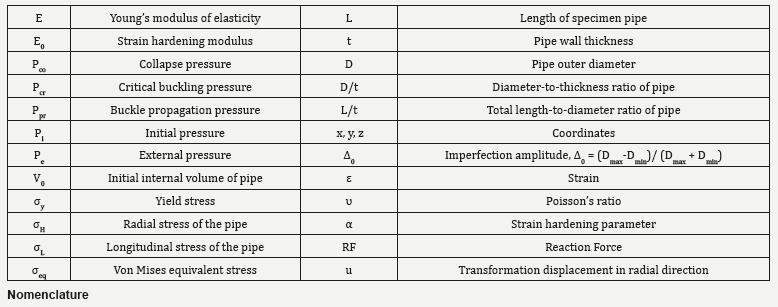
Introduction
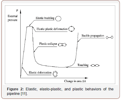
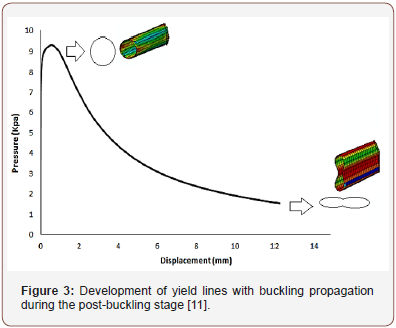
Subsea pipelines are externally loaded by a constant source of hydrostatic pressure. Local buckling can occur at pressures much lower than that required for critical buckling (Pcr), and after one region has been compromised, the zone of damage may begin to expand along the length of the pipe leading to eventual collapse of the pipeline [1,2]. During buckling and the ensuing propagation of damage, significant changes are found to occur in the cross section of the pipe geometry. An analysis of post-buckling behavior prior to total collapse should be considered in order to better understand the gradual failure mechanisms of these structures in both the radial as well as longitudinal directions [3-6]. As depicted in Figure 1, the phenomenon of buckling tends to flatten the pipeline in cross section locally, while propagation of this damage longitudinally may be characterized by three zones: the near-end buckled and far-end unbuckled regions, and a transition of pipe length between the two (Figure 1). After buckling initiation, damage propagation reaches a steady state for which the external hydrostatic pressure is constant. Buckling propagation stops when the external hydrostatic pressure is lower than the buckle propagation pressure [7]. According to the elastic stability theory, deformation of pipeline occurs in two stages: pre-buckling and post-buckling [8]. Research has shown that in loads lower than the buckling load, deformation of pipeline is based on a stable pre-buckling path [9,10,12]. As pressure increases, the pipeline section starts to develop plastic hinges and then begins to fail. With the continual increase in pressure, the pipeline undergoes further deformation in the radial direction until the onset of pipeline buckling at a certain external pressure, i.e. the critical buckling load Pcr. Beyond this point, the pipeline behavior is described by the post-buckling path, which may be unstable for pipelines with elasto-plastic materials. The pipeline deformation diagram is portrayed in Figure 2 Illustrated in Figure 3 is also the development of yield lines with buckling propagation along the pipeline section (Figure 2 & 3).

Behavior of pipelines in response to external pressure has been the subject of numerous studies, which have shown that length of the pipe and ratio of its diameter to the wall thickness play a decisive role in the pipe’s resistance against buckling. According to Bresse [13], the stability of pipelines under hydrostatic pressure as based on small deflection theory, the critical buckling pressure Pcr can be obtained using the following equation:

In Eq. (1), R is the pipeline radius, E is the Young’s modulus of elasticity of the pipeline material and I is the moment of inertia of the pipeline cross-section. A similar formula has been developed by Bryan [14], i.e. Eq. (2), for a freestanding long pipeline subjected to hydrostatic pressure. The difference between Bryan’s and Bresse’s formulae is the replacement of E with E/(1-ν2). This accounts for plane strain conditions in computing the buckling pressure of infinitely long pipes.

In the above equation, D is the mean diameter of the pipeline, E is the Young’s modulus of elasticity of the pipeline material, t is the mean thickness of the pipe wall, and ν is Poisson’s ratio. The first research introducing the buckling propagation in pipelines was the work of Mesloh et al. [15] followed closely by Palmer and Martin’s study [16]. In the latter study, it was claimed that the propagation pressure can be determined using the strain energy of the collapsed cross-section of the pipe with an equation proposed for this purpose. In this research, the experimental values obtained with low diameter-to-thickness ratios (D⁄t) were greater than the predicted results. This issue is expected in deep water conditions considering the effects of plastic deformation [7]. The studies of Johns et al. & Mesloh et al. [1,15], took an experimental approach to this subject and determined the adequacy of different arrestor geometries for stopping the buckling propagation. These studies resulted in the empirical formula of propagation pressure Ppr based on diameter, thickness, and yield stress (σY).

Palmer & Martin [16] proposed the following formula for predicting the buckling propagation pressure in pipelines Ppr. This equation is based on the assumption that the material is rigid and perfectly plastic. In their model, four plastic hinges govern the collapse mechanism during buckling propagation based on an energy balance.

Barlow’s formula [17], i.e. Eq. (5), is used for calculating the hoop stress in thin-walled cylinders with D0/t>20, in which D0 is the outer diameter and t is the wall thickness.

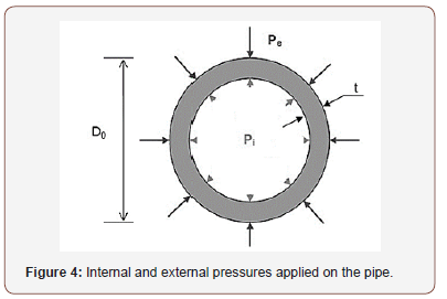
Where, Pi is the internal pressure and Pe is the external pressure applied on the pipe as shown in Figure 4, and H σ is the hoop stress in this equation. It is noted that the use of this equation is limited to thin-walled pipes [18].
Internal and external pressures induce hoop stress, which results in expansion of the pipe’s circular cross-section. On this basis, while studying the fully- or partially-anchored pipelines, one can expect to observe the Poisson effect, i.e. the expansion or compression of material in one direction due to an external force which entails compression or expansion reaction in the other direction [19,20]. Thus, because of the Poisson effect, the hoop stress in an anchored pipeline creates longitudinal stress. Pressure-induced longitudinal stresses in an anchored pipeline can be obtained from the following equation:

Von Mises equivalent stress eq σ can be determined using Eq. (7) by considering the hoop and longitudinal stresses discussed above.

Local buckling occurs when the pipe undergoes localized deformations which involves only a small portion of the pipeline. This buckling mode occurs when the pipe wall thickness is relatively small compared to the pipe diameter. The pressure that can trigger local buckling, which is also known as buckle initiation pressure (Pi), is normally lower than the collapse pressure and has been the subject of several investigations. Shell Development Company has provided the following empirical equation for calculating the buckle initiation pressure. Eq. (8) shows that reducing the pipe wall thickness results in reduced buckle initiation pressure and increases the chance of unexpected local buckling in the weakened sections [21-23].

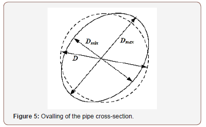
The amount of deformation (ovalling) of the pipe cross-section relative to its initial round shape may be quantified using Eq. (9). In this equation, f0 denotes the cross-section deformation and Dmax and Dmin are the maximum and minimum diameters of the deformed pipe as illustrated in Figure 5 (Figures 4,5).

One effective method to determine the buckle propagation pressure in offshore pipelines is the numerical simulation. In a study by Jensen [24], comparison of theoretical and numerical results obtained for propagation pressure in a long circular cylindrical shell based on thin shell theory and small strain approximation as well as different elastic-plastic material descriptions showed that the results closest to the experimental values are the ones obtained with J2 flow theory [25]. Dyau & Kyriakides [26] performed a systematic review on the experimental data regarding the propagation pressure in the pipes and introduced a numerical model based on the Sander’s nonlinear shell kinematics with small strains and large displacements. In a study by Pasqualino & Estefen [15,27], the thin shell theory proposed by Sanders [28] was used to develop a 3D model based on finite strains and finite displacements. In the next step, this model was used to obtain an estimate for propagation pressure of Deepwater pipelines. They reported a good agreement between the numerical and experimental results obtained for six small-scale steel pipes with diameter-to-thickness ratios of 16, 21, and 24. In another study reported by Xue & Hoo Fatt [29], steadystate buckle propagation in a corroded pipeline under external hydrostatic pressure was examined using rigid-plastic theoretical analysis and finite element analysis with ABAQUS. The results of this study showed that depth and angular extent of the corrosion are determining factors of buckle propagation pressure and buckling mode. Moreover, the studies performed Kyriakides [30] and Kyriakides & Vogler [31] focused on the buckle propagation in pipe-in-pipe systems subjected to external pressure. These studies followed both experimental and analytical approaches and resulted in an empirical formula for propagation pressure as well as design recommendations. Some researchers have conducted comprehensive research on the buckling of pipelines have been studied [32-34]. In this paper, the buckling behavior of pipes with different diameter-to-thickness ratios, subjected to external hydrostatic pressure is investigated to gain a better understanding of stability performance of pipelines. In addition to theoretical investigations, some numerical models with different geometrical properties as well as imperfections and boundary conditions are developed using the finite element software, ABAQUS [35]. Furthermore, a 3D finite element model of a steel pipe is developed using ABAQUS in order to simulate the buckle propagation. Finally, the numerical results of this study are evaluated and compared with the results available in the literature.
Geometrical and Material Properties of Considered Pipes
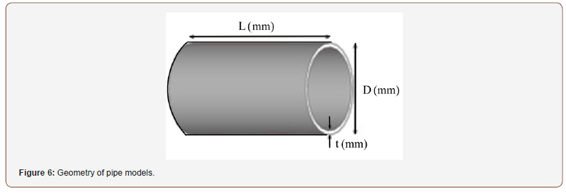
In this study, four new specimens with the geometry similar to that of specimens used in previous research were developed. The resulting eight specimens were then divided into two groups based on the status of boundary condition. The geometry of pipeline developed with two simple supports is shown in Figure 6. The geometric properties assumed for the specimens are given in Table 1. The specimens are labeled as PE-X-Y, where the number replacing X represents the specimen diameter D (mm) and the number replacing Y is the specimen thickness t (mm) (Table 1).
Table 1: Geometry of pipe models.

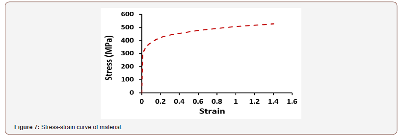
For these the modulus of elasticity analyses, set to 2.06E5 MPa and the Poisson’s ratio, ν, is 0.3 and the yield stress of the metal is selected as 488 MPa; the stress-strain curve of this material is shown in Figure 7 (Figures 6,7).
Finite Element Modeling Details
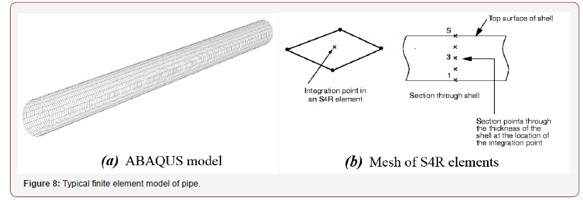
In this part of the study, the ABAQUS was used to simulate the loading, collapse and buckle propagation of models. We modeled, a 3 m axisymmetric pipe span with material nonlinearities emulating the hardening and residual stresses due to damage. The longitudinal symmetric boundary conditions used for both ends of the pipe restricted longitudinal extension (along z-axis) and outof- plane bending (about x and y axes). Table 1 provides the pipe geometric and material specifications [36,37] and Figure 7 shows the stress–strain curve of the material in [35,36]. The modeling of the pipe span was performed with 4-noded S4R quadrilateral shell elements. These elements have a reduced integration and finite strain kinematics, which allows 5 integration points to be placed across the shell thickness, and are not dominated by in-plane bending, shown in Figure 8 [35].

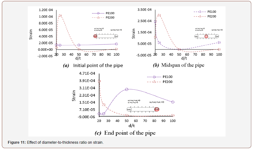
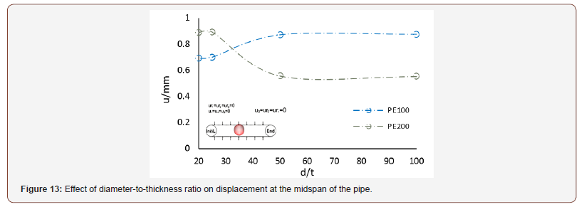
The study examines the effect of diameter-to-thickness ratio on stress, strain, reaction force and displacement at the midspan of the pipeline to assess the shell buckling of this cylindrical structure. The nonlinear response was obtained with the nonlinear analysis based on modified Riks’ approach [38]. Through this analysis, determine the maximum values of stress, strain, reaction force and displacement at the two ends and midspan of the pipeline. In this analysis, geometrical non-linearity has been incorporated as previously described. This analysis also determines the critical load in the point at the peak of load-shortening curve [35,39]. In ABAQUS, buckling of a pipe subjected to external hydrostatic pressure can be analyzed through two methods: Eigenvalue (or Linear) Buckling Analysis, and Nonlinear Buckling Analysis. The former method ignores the nonlinear effects, so its results are usually inaccurate, but it is very useful for identification of buckling modes and is therefore used in this study for this purpose. Nonlinear buckling analysis is the most accurate method for determining the buckling capacity. In this study, first a linear static analysis was conducted on the pipeline with the described geometry and material properties and subjected to uniform external pressure to obtain the stress stiffness matrix. Then an eigenvalue buckling analysis was performed to obtain the buckling modes and the corresponding critical loads [38,40]. In the buckling analysis, the first buckling mode is usually the dominant one. The first buckling mode of the pipe, which is shown in Figure 9, is in fact the deformation in the actual pipe after propagation of buckling (Figure 9).
Buckling critical pressure was obtained based on the first mode obtained with this analysis. The results show that, as expected, local buckling of pipelines (like other thin-walled structures) is governed mainly by their nonlinear behaviors and those analyses that ignore this issue produce essentially inapplicable solutions [37,40].
Numerical Results
The numerical results obtained on the effects of diameter-tothickness ratio on the stress, strain, reaction force, and displacement along the radius of the pipe subjected to hydrostatic pressure and modeled with clamped boundary conditions are summarized in Table 2
Table 2: Summary of results on the effects of diameter-to-thickness ratio.
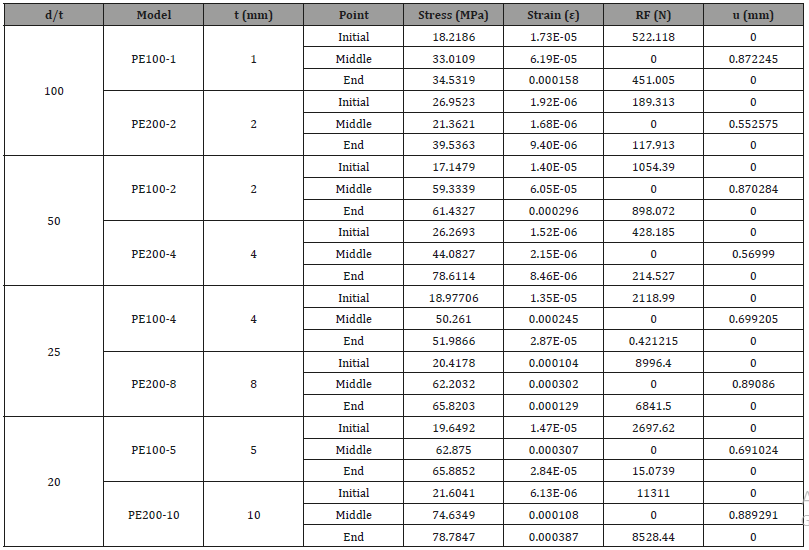
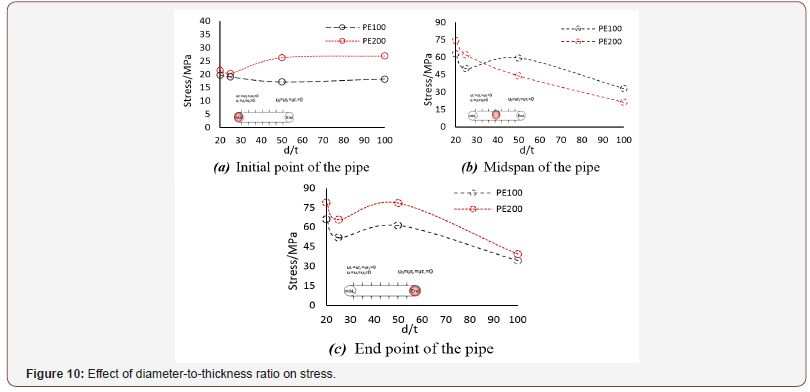
These results are best to be compared in plots, as graphical representation of the results allows the comparison to be made visually and thereby facilitates the interpretation. Therefore, the results of Table 2 are also plotted in Figures 10-13 to simplify the comparison of the effect of diameter-to-thickness ratio on stress, strain, reaction force and displacement (Figures 10-13).

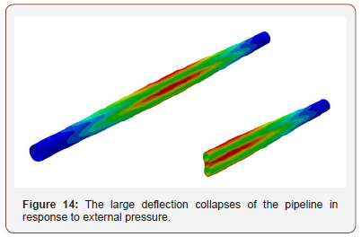
The large deflection collapse behavior of the pipeline model was also investigated. Figure 14 shows this behavior of this 3D model in response to external pressure (Figure 14).
Discussion and Conclusion
The aim of this paper was to assess the effect of diameterto- thickness ratio on the pipeline exposed to external pressure. This study found that maximum stress and strain are key values for large deflection analysis and prediction of the pressure in externally pressurized long pipelines. The major results of this study can be summarized as follows: As the collapse mode number (n) increases, so does the collapse pressure. According to presented discussions and previous studies, the major factors affecting the failure load are the environmental conditions (type of loading and load history), geometry of the pipe (diameter to thickness ratio; D/t), mechanical properties of the pipe material, and presence of initial geometric imperfections. This study found that for a constant diameter to thickness ratio (D/t), a pipe having a higher diameter and thickness can sustain 10 to 22 percent greater loads at its ends, which implies the direct effect of diameter and thickness on the stress induced in the pipe. Generally, a reduction in D/t leads to a reduction in the local collapse pressure of the pipe. Local buckling in a pipe can propagate along its length and leads to the collapse of pipeline. Buckle propagation is an inelastic failure which starts with a local lateral buckling and develops along the pipe length rendering it unusable. Depending on the external pressure on the pipe, buckle propagation occurs in pressures between the collapse pressure and propagation pressure. In pressures lower than the propagation pressure, buckling remains local and does not expand. 5 percent ovalling of the pipe cross-section reduces the buckle initiation pressure by 4 percent. Buckle propagation pressure of a pipe is far lower than its collapse pressure, in other words, buckling propagates at pressures as low as 20 to 25 percent of the collapse pressure.
Acknowledgement
None.
Conflict of Interest
No conflict of interest.
References
- Johns TG, Mesloh RE, Winegardner R, JE Sorenson (1975) Inelastic buckling of pipelines under combined loads, Proceeding of the Offshore Technology Conference, Houston TX, OTC Paper 2209 2: 635-646.
- Ju GT, Kyriakedes S (1991) Bifurcation buckling versus limit load instabilities of elastic– plastic tubes under bending and external pressure. ASME J Offshore Mech Arct Eng 113(1): 43-52.
- Xue J, Hoo Fatt MS (2001) Propagating buckles in corroded pipelines. Mar Struct 14(6): 571-592.
- Xue J, Hoo Fatt MS, Liu Y (2000) Steady-state buckle propagation in corroded pipelines, Proceeding of the 10th International Offshore and Polar Engineering Conference, Seattle, Washington, USA, May 28 –June 2, pp. 197-204.
- Hoo Fatt MS, Xue J (2002) Buckling of a non-uniform shell subjected to external hydrostatic pressure. Eng Struct 24(8): 1027-1034.
- Hoo Fatt MS, Xue J (2005) Symmetric and anti-symmetric buckle propagation modes in subsea corroded pipelines. Mar Struct 18(1): 43- 61.
- Pasqualino IP, Estefen SF (2001) A nonlinear analysis of buckle propagation problem in deep-water pipelines. Int J Solids Struct 38: 8481-8502.
- Hutchinson JW, Koiter WT (1970) Post-buckling theory. Appl Mech Rev 23: 1353-1356.
- Kyriakedes S, Babcock CD (1981) Large deflection collapse analysis of an inelastic inextensional ring under external pressure. Int J Solids Struct 17(10): 981-993.
- Kyriakedes S, Arikan E (1983) Postbuckling behavior of inelastic inextensional rings under external pressure. J Appl Mech 50(3): 537- 543.
- Showkati H, Shahandeh R (2010) Experiments on the buckling behavior of ring-stiffened pipelines under hydrostatic pressure. J Eng Mech 136(4): 464-471.
- Fairbairn W (1858) On the resistance of tubes to collapse. Philos Trans R Soc Lond 148: 389-413.
- Bresse M (1866) Cours de méchanique appliquée. (2ndEdn), Paris, France.
- Bryan GH (1888) Application of the energy test to the collapse of a long pipe under external pressure. proceeding of the Cambridge Philosophical Soc, Proc UK, Cambridge 6: 287-292.
- Mesloh RE, Sorenson JE, Atterbury TJ (1973) Buckling and offshore pipelines. Gas Mag 740-743.
- Palmer AC, Martin JH (1975) Buckle propagation in submarine pipeline. Nature 254: 46-48.
- Mohitpour M, Golshan H, Murray A (2000) Pipeline Design & Construction, A Practical Approach, ASME.
- Shunfeng Gong, Bin Sun, Sheng Bao, Yong Bai (2012) Buckle propagation of offshore pipeline s under external pressure. Marine Structures 29(1):115-130.
- ABS, American Bureau, Houston (2005) Guide for Building and Classing Subsea Pipeline Systems and Risers 64-01.
- Rabee Shamass, Giulio Alfano, Federico Guarracino (2014) A numerical investigation into the plastic buckling paradox for circular cylindrical shells under axial compression. Engineering Structures 75: 429-447.
- Jianbei Zhu, Mario M Attard, David C Kellermann (2015) In-plane nonlinear localised lateral buckling of straight pipelines. Engineering Structures 103: 37-52.
- Zhaohui Hong, Run Liu n, Wenbin Liu, Shuwang Yan (2015) Study on lateral buckling characteristics of a submarine pipeline with a single arch symmetric initial imperfection. Ocean Engineering 108: 21-32.
- Ifayefunmi (2016) Buckling behavior of axially compressed cylindrical shells: Comparison of theoretical and experimental data. Thin-Walled Structures 98: 558-564.
- Jensen HM (1988) Collapse of hydrostatically loaded cylindrical shells. International Journal of Solids and Structures 24(1): 51-64.
- Chakrabarty J (2006) Theory of plasticity. Oxford Elsevier Butterworth- Heinemann, UK.
- Dyau JY, Kyriakides S (1993) On the propagation pressure of long cylindrical shells under external pressure. International Journal of Mechanical Sciences 35(8): 675-713.
- Pasqualino IP, Estefen SF (2001) A nonlinear analysis of the buckle propagation problem in deep water pipelines. International Journal of Solids and Structures 38: 8481-502.
- Sanders JL (1963) Nonlinear theories of thin shells. QAppl Math 21(1): 21-36.
- Xue JH, Hoo Fatt MS (2005) Symmetric and anti-symmetric buckle propagation modes in subsea corroded pipelines. Marine Structures 18: 43-61.
- Kyriakedes S (2002) Buckle propagation in pipe-in-pipe system. Part I: experiments. Int J Solids Struct 39(2): 351-366.
- Kyriakedes S, Vogler TJ (2002) Buckle propagation in pipe-in-pipe system. Part II: analysis, International Journal of Solids and Structures 39(2): 367-392.
- Wang FC, Li W, Han LH (2019) Interaction behavior between outer pipe and liner within offshore lined pipeline under axial compression. Ocean Engineering 175: 103-112.
- Kaiser MJ (2017) Offshore pipeline construction cost in the U.S. Gulf of Mexico. Marine Policy 82: 147-166.
- Li Z, Tang F, Chen Y, Tang Y, Chen G (2019) Elastic and inelastic buckling of thin-walled steel liners encased in circular host pipes under external pressure and thermal effects. Thin-Walled Structures 137: 213-223.
- Simulia AB (2012) AQUS theory manual. Dassault Systems Version 6(12).
- Riahi F (2009) (Masters Research Thesis) Influence of Ring Stiffeners on Ultimate Strength of Submarine Pipelines under Hydrostatic Pressure. Urmia, Iran: University of Urmia. Middle East.
- Jianbei Zhu, Mario M, Attard, David C Kellermann (2015) In-plane nonlinear localised lateral buckling of straight pipelines. Engineering Structures 103: 37-52.
- Riks E (1979) An incremental approach to the solution of snapping and buckling problems. International Journal of Solids and Structures 15(7): 529-51.
- Falzon BG (2006) An introduction to modelling buckling and collapse.
- Shahandeh R, Showkati H (2016) Influence of ring-stiffeners on buckling behavior of pipelines under hydrostatic pressure. Journal of Constructional Steel Research 121: 237-252.
-
Tadeh Zirakian, Farhad Riahi, David Boyajian, Mansour Mohammadi, Alaeddin Behravesh. Stability Performance Assessment of Pipelines under Hydrostatic Pressure. Cur Trends Civil & Struct Eng. 1(5): 2019. CTCSE.MS.ID.000524.
-
Hydrostatic Pressure, Pipeline, Buckling, Hydrostatic pressure, Diameter-to-thickness ratio, Numerical simulation, Stability, Deepwater pipelines, Thin-walled structures
-

This work is licensed under a Creative Commons Attribution-NonCommercial 4.0 International License.


