 Research Article
Hybrid Subsea CCS System-CO2 Storage in Offshore Ultra Deep-Water Salt Caverns
Alvaro M Costa1*, Pedro VM Costa1, Julio R Meneghini2, Kazuo Nishimoto2, Claudio M Sampaio2, Felipe Ruggeri3, Camila Brandão4 and Alexandre Breda4
1MODECOM-Technology in Geomechanics and Computing Modeling, Brazil
2US-State University of São Paulo, Brazil
3Argonautica–Engineering and Research, Brazil
4Shell, Brazil
Alvaro M Costa, MODECOM-Technology in Geomechanics and Computing Modeling, Brazil.
Received Date: December 14, 2018; Published Date: January 25, 2019
Abstract
Computational geomechanics is the field of computational mechanics where geo-engineering systems are analyzed using the prinCurrently there is a demand for CCS of large quantities of CO2 associated with CH4 in the pre-salt offshore oil fields in Brazil. The pre-salt reservoirs have as caprock 2000 meters of continuous rock salt. Rock salt is a special geomaterial. It has negligible permeability and porosity, is able to support very high stresses, develops the self-healing effect, fractures will heal only with time and a good geomechanical project can design very large openings in the salt body. In Brazil the rock mechanics and computing modeling related to underground excavations in salt rock started in the years 1970´s with very complex challenges, starting with the project of an underground mining of sylvinite (potash ore) overlying tachyhydrite, a very weak salt rock, solving the challenges of the solution mining of salt caverns, for brine production, in bedded stratified halite with intercalations of shales, development of special geomechanical projects of oil wells for drilling through very thick stratified salt rock barrier and finally the application of salt caverns opened by solution mining for natural gas storage and CCS of CO2. Salt caverns onshore, opened by solution mining have been used since the years 1950´s to store hydrocarbons and contaminants. A good example of a very large underground storage is the Strategic Petroleum Reserve in the United States, storing since 1974 around 800 million barrels of crude oil. Today there are more than 4000 caverns opened by solution mining for the storage of oil and gas. This article introduces a new concept called the Hybrid Subsea CCS System, which performs all the offshore CO2 separation process with subsequent storage in underground salt caverns offshore. Today much is said on the concept of “Subsea Factory” in the global oil industry, which is every day closer to become a reality. Many operators have been applying high R&D investments in bringing down to the sea floor equipment from the deck of the production platforms like: multiphase pumps, oil separators, electrical transformers, gas compressors, among other pieces of equipment, reducing the size of the floating platforms and in some sites, becomes the only solution available due to the water depth, which cause a great limitation in the elevation of the hydrocarbon through conventional and even with non-conventional riser systems. The main challenge of doing a complete Subsea “factory” or develop the “Subsea CCS System” is the storage. Shell, USP (University of São Paulo) and FAPESP (Sao Paulo Research Foundation) are developing a R&D project of a hybrid system using partially the subsea factory technology with the high structural performance of salt rock caverns, opened by solution mining, in ultra-deep water. This hybrid system is expected to do at the same time the separation between the natural gas and CO2, Carbon Capture and Storage of CO2 and allowing the monetization of the separated natural gas. This paper describes the conceptual design of this hybrid system showing the steps from the drilling phase of the wells, the process of opening the salt caverns by solution mining, the subsea equipment required, the basic logistic system to servo control this equipment and the geomechanical project of salt caverns to store Natural Gas and CO2 in salt domes in ultra-deep water.
Keywords:Salt caverns; Gas and CO2 Storage; Rock salt; Creep strain rate; Stability analysis
Introduction
Governments, corporations and other organizations increasingly recognize the importance of stabilizing the atmospheric concentration of greenhouse gases (GHG). Climatologists agree a concentration increase in GHG contributes to global climate change Citation: Alvaro M Costa, Pedro VM Costa, Julio R Meneghini, Kazuo Nishimoto, Claudio M Sampaio, et al. Hybrid Subsea CCS System-CO Page 2 of 22 2 Storage in Offshore Ultra Deep-Water Salt Caverns. Cur Trends Civil & Struct Eng. 1(3): 2019. CTCSE.MS.ID.000513. and CO2 is reported to dominate these emissions. The process of carbon capture and storage in geologic media has been identified as an important means for reducing anthropogenic greenhouse gas emissions [1]. Noting various ways to sequester CO2 in geological media to include, utilization in EOR operations, disposal in disused oil and gas reservoirs, replacement of methane in coalbeds, injection in deep saline aquifers and storage in salt caverns, S Bachu suggested several criteria to be considered when evaluating the potential of a sedimentary basin for CO2 sequestration to include, its tectonic setting and geology, the basin geothermal regime, the hydrodynamic regime of formation waters, the hydrocarbon potential and basin maturity, economic aspects relating to access and infrastructure and socio-political condition [2].
Salt cavern has been identified as one of the best mediums for underground storage of gas noting the main reasons to include: (i) Low permeability, the permeability of rock salt is about 10-21-10-24 m2, thus can provide excellent sealing of the salt cavern. (ii) Good mechanical properties, damage self-recovery capability of rock salt can ensure the safety of salt cavern with frequent changes of gas pressure. (iii) Solution in water, rock salt is easily dissolved into water, which facilitates the construction and shape control of the salt cavern. (iv) Abundant resources, rock salt resource is a very rich mineral resource with wide distribution and large reserves, therefore the site used to construct salt cavern gas storage near where it’s required can be easily found [3]. Salt formation can be found in almost every part of the world with some exception around the Pacific Rim, salt caverns can be constructed in naturally occurring thick salt domes, deep underground and reported salt caverns for gas storage can be formed through a leaching process by pumping fresh or sea water to dissolve the salt and removing the resulting brine via a single well, which then serves for gas injection and withdrawal [4].
In 2006, through the pioneer well TUPI (RJS-628), one of the largest oil provinces in the world for pre-salt reserves was discovered, stretching from the north to south of Brazilian continental front, between 200 km and 300 km away from the coast [5]. They are carbonate reservoirs underlying 2000 meters of stratified salt rock. Many provinces producing oil and natural gas globally are associated with reservoirs underlying thick layers of salt, consisting largely of halite (NaCl) whose mechanical resistance favors drilling of wells. Peculiar to Brazilian province consist of stratification of thick layers of halite with intercalations of carnalite and tachyhydrite salt rock, whose creep strain rate is approximately two orders of magnitude higher than halite’s rate for the same temperature and pressure state variables [5]. The presence of these rocks causes the wells to close quickly during the drilling process and usually induce collapse of casings. Drilling through very thick stratified salt rock layers of the pre-salt posed the main technological challenges to be overcome to reach the reservoir rock. However, the challenge was tackled by adopting similar technique implemented in the successful sylvinite exploitation activities in the evaporitic basin of Sergipe in the northeast of Brazil. The deposit of sylvinite in Sergipe has similar peculiar geological characteristic, the presence of tachyhydrite underlying the sylvinite ore. Tachyhydrite, (CaCl2.MgCl2.12H2O), develops a creep strain rate two orders of magnitude higher than sylvinite for the same state variables, temperature and stress, it also possess very low shear strength, 20 times smaller than sylvinite and develops an extremely high hygroscopic phenomenon when exposed to air. Thus, mining sylvinite in Sergipe required careful studies. It was therefore paramount to study the rock mechanics of the mine to understand the interaction between the tachyhydrite creep behavior with the panels and galleries excavations [6]. The technological solution developed to mine sylvinite directly on top of tachyhydrite resulted from the application of computational mechanics by the use of the COVES program family, developed in the end of 1970s Costa and through field experimentation and laboratory tests of rock mechanics.
The petroleum in the pre-salt reservoirs in Brazil possess very high GOR (gas-oil ratio) with high content of carbon dioxide. Laboratory analyzes have shown that CO2 found in the pre-salt reservoirs is of mantle origin, migrating to the pre-salt reservoirs through the intense presence of geological faults between crystalline and the carbonate reservoirs [5]. Due to the pressure and temperature state variables in the reservoirs, the CO2 is in the liquid state, or supercritical and mixed with the hydrocarbon inside the reservoirs. However, when it is produced at the surface, it gasifies and mixes with the other monetizable gases, methane CH4, ethane C2H6 etc. [7]. Some of these gasses are treated and separated on the platform using the membrane technology, reducing the CO2 content to 3%, and it is possible to transfer a portion of the natural gas to shore through carbon steel pipelines. The remaining part possessing mainly CO2 gas is reinjected back into the reservoir. At the beginning of the life of the fields, the reinjection of this gas supports EOR (enhanced Oil Recovery) in a process called WAGWater Alternated Gas. However, as the same molecule of CO2 recycles several times within the drainage radius of the wells, the CO2 content starts to increase significantly, making it unfeasible for its treatment in the platform, which may force the closure of production wells.
At the beginning of production of the pre-salt reservoirs, in the field development plan, there was a hypothesis of reinjecting the CO2 gas stream into nearby saline aquifers which could only be selected below the pre-salt reservoirs. In view of the small layer thickness of the sediment above the salt layer (between 500m and 800m) which cannot withstand the envisaged volume CO2 at the injection pressure and temperature demanded [5]. However, the saline aquifer below the pre-salt is intercepted by a large number of geological faults, which naturally feed without anthropogenic action, the pre-salt reservoirs with mantle CO2. The injection of CO2 under high pressures into these reservoirs possessing non-sealing geological faults or even with some sealing faults in place would only increase their permeability. This process will create a vicious cycle, increasing the level of reservoir contamination and reducing field production over time. With these limiting prevailing conditions of the pre-salt reservoirs, the salt rock becomes a strategic geomaterial for the process of confining the gas stream with high CO2 content, since this gas can be injected and contained in salt caverns instead of reinjecting into the reservoirs. The deposition of salt rock overlying the pre-salt carbonate reservoirs can be stratified over time into two distinct phases in the evaporation process. With the opening of the continents about 120 million years ago, the Atlantic Ocean penetrated the continent with seawater, that by evaporation, the salt was deposited directly on top of the stromatolites or micorbiolites, which is the carbonate oil reservoir of the pre-salt. It is possible to verify that in the layer of salt rock directly laying on top the reservoir in general we find halite only. In a second phase of formation of the salt deposits, through different cycles of aridity on the planet and tectonism, different salts, such as anhydrites, carnalites, silvinites and finally tachyhydrite, have been deposited on the basal halite layer, which corresponds to the last one salt to be deposited in a complete cycle.
The salt deposits extend from the continent up to hundreds of kilometers in direction of the ocean. The part of the deposit that was in the continental slope, trigger by the creep phenomenon began to move towards the deep ocean. This relative movement between the substantiated basal part of pure halite and the stratified section of the deposit caused the stratified section to be perforated by giant salt domes of pure halite. Perforating salt diapers are the most suitable sites for the construction of salt caverns because they made of pure halite without stratification. The environment in which the research project presented in this paper is being developed has very peculiar characteristics, being unprecedented worldwide and requiring a deep multidisciplinary knowledge: Offshore oil engineering in ultra-deep waters, drilling wells in front of thick layers of stratified salt rock, geomechanical design of underground salt rock excavations by conventional and dissolution method, cavern construction technologies for offshore dissolution, fluid mechanics and gas thermodynamics and CCS in salt caverns. To date, there are no natural gas or other hydrocarbon storage systems in offshore salt caverns. Only the Gateway Project in the Irish Sea is upcoming, it involves a project to store natural gas in offshore salt caverns in shallow water, 25 meters, but has not yet been built [8].
Simulation results obtained shows the technical feasibility of huge storage volumes of natural gas and CO2 in giant salt caverns offshore. For the case study presented in this paper, using giant salt caverns of 450m high by 150m in diameter, one cavern can store 4 billion Sm3 or 7.2 million tons of CO2. The salt dome studied can accommodate the construction of 15 caverns, which provides the confinement of approximately 108 million tons of CO2.
Geomechanical project of the Caverns
Creep behavior of salt rock
In the 1970´s Costa [2], developed a family of computer codes denominated COVES, based on the Finite Element Method applied to general geomechanical projects. One of the applications was in the design of the potash mine located in the state of Sergipe in Brazil. These computer codes, as it is presented in Costa [2], were validated by an extensive set of classical solutions of the international technical literature.
The COVES 2 program is extensively applied in the simulation of the behavior of underground excavations [2,6-13], and considers the non-linear physical visco-elastic and elasto-plastic phenomenons, with different constitutive laws for representing the geomechanical behavior of geomaterials. The program has shown excellent stability and convergence in predicting the creep phenomenon under conditions of high-temperature levels and highdifferential stresses of rock salt (HPHT excavations). The program is also able to simulate the behavior of the excavation in progress, through the technique of automatic mesh rezoning. The excavation formulation and algorithm is also a differential advantage of the program providing valuable inputs for the oil industry in wells that cross thick stratified layers of rock salt. The COVES 2 program has different constitutive creep laws for representing the creep phenomenon of rock salt. The creep phenomenon of rock salt can be represented by potential laws and laws based on mechanisms of deformation. The potential creep law was studied by Lomenick & Bradashaw [2,14]. This work, sponsored by the Waste Isolation Service of United States, had the purpose, to have old salt mines as a final destination of nuclear waste.
The potential law is a function of the absolute temperature in Kelvin, time and differential stress:

Where:
ε → Creep deformation
σ → Differential stress
T→ Absolute temperature in Kelvin
t→ time
K, a, b e c → creep constants
The potential law has a limitation to represent the long-term creep behavior of rock salt, that is not compatible with the primary principle of a nuclear waste disposal, which must be stable for hundreds of years. Darrell E Munson, as a Metallurgist Engineer, Munson [4,15-19], studied a new constitutive creep law based on mechanisms of deformation, similar to the behavior of steel under high temperature. The constitutive creep law that incorporates all of the parts related to the creep deformation mechanisms (multimechanism deformation-MD) considers the following mechanisms, which depend to the temperature and stress and intergranular behavior of salt.
1. Movement of dislocations by slipping (dislocation glide), Eq. 2a;
2. Solubilization of intergranular contacts between rock salt grains, resulting from pressure or undefined mechanisms, Eq. 2b.
3. Movement of dislocations by climbing (dislocation climb), Eq. 2c.
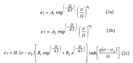
Larger contributions by a given mechanism depend on the conditions of temperature and differential stress applied to the rock salt. In engineering designs for the underground mining of evaporitic rocks or well designs in salt zones, the MD law is used, and its application is restricted to the steady-state creep interval that is dominant in these types of projects in common engineering practice [4,13,15,20,21], neglecting Eq. 2c. Thus, the constitutive equation for stationary or permanent creep of the double deformation mechanism is given by the following equation

Costa [ 4,13,15,20,21], implemented this constitutive creep law in the computer code COVES 2, to represent the long-term creep behavior of the excavations of the potash mine overlying tachyhydrite.
Where:
1. ε ̇ – Strain rate due to creep at the steady state condition;
2.  – Reference strain rate due to creep (in steady state);
3. σef – Creep effective stress [Generalized stress];
4. σ0 – Reference effective stress (Yield stress of the deformation mechanism by slipping);
5. Q – Activation energy (kcal/mol), Q=12 kcal/mol [4,13,15,20-23];
6. R – Universal gas constant (kcal/mol.K), R=1.9858E-03;
7. T0 – Reference temperature (K);
8. T – Rock temperature (K);
9. Ai and Bi = Constants;
10. H = Heaviside step function;
11. ni = Stress exponent;
12. G = Shear modulus.
Mechanics Properties
The background used in the design of the salt caverns and well drilled through thick stratified salt rock are based on the succsess rock mechanics studies conducted at the potash mine located at the State of Sergipe, Brazil. The potash mine received hundreds of instrumentation sections, most closure measurements, to control the global stability of the excavations, in comparison with the simulation results.
As part of the rock mechanics studies used to enable the mining of the lower sylvinite layer in the potash mine, an experimental panel, “D1” [4,6,7,9-13,15,19] was designed and excavated in the lower sylvinite layer, overlying tachyhydrite. The excavation of this experimental panel started in March of 1988 and it was necessary about three years to finish the excavation together with the installation of the instruments. 7 years of measurements was carried out in this panel. The installation of the instruments and measurements in this panel and all over the mine has been conducted, since 1992, by the Rock Mechanics and Mining Engineering Teams of Companhia Vale do Rio Doce, today, Vale S.A, and MODECOM Costa [4,15]. Rock mechanics studies at the Sergipe Potash mine have been in progress for more than 35 years, following the model started in the experimental Panel D1, which ensures reliability in the rock mechanics properties used and, in the models, adopted. The rock mechanics properties and modeling procedure applied for the project of the caverns follows the technology developed for the potash mine. Table 1 shows the rock mechanics properties isolated from the research conducted in the Sergipe potash mine with 35 years of successful results (Table 1).
Table 1:Rock Mechanics Properties isolated by the research conducted in the Sergipe potash mine.
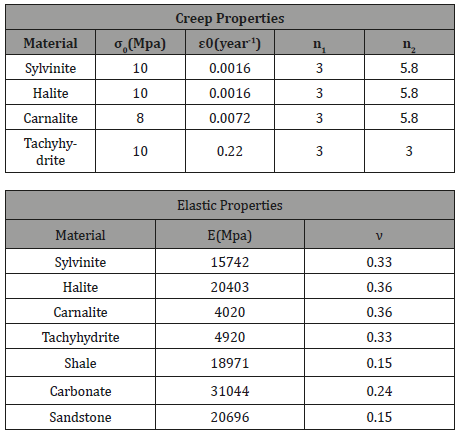
Temperature: 43˚C to 48˚C
Depth: 450-470m
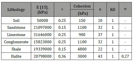
During the excavation of the development galleries and mining panels there was a continuous monitoring of closure by closuremeters and displacements inside the salt rock by extensometers. These measurements were compared to the computer simulation results obtained by COVES 2. From these comparisons, it was possible to evaluate the stability of the openings and the necessity of the installation of additional supports to the openings, like bolts, steel structures and wooden cribs. For the lower sylvinite, this process also allowed the adjustments of the openings dimensions. The shear strength properties of rocks with brittle behavior are based on laboratory tests conducted by IPT (Instituto de Pesquisas Tecnológicas do Estado de São Paulo) on specimens from the pilot well 23 of the service shaft of the potash mining in Sergipe [38]. The shear strength properties are the same used in the potash mine of Taquari-Vassouras in Sergipe, in light of the experience gained in the application of these parameters [24]. The properties of deformability of the salt rocks are obtained from indirect mode from the wave propagation velocities “VS” and “VP” [24]. In the case of brittle rocks, the Sonic profile data is used, held by Schlumberger on the pilot well GTP-23 of the service shaft of the mine. Table 2 presents the mechanical properties of deformability and shear strength of rocks, present in the geological section of analysis employed in the simulations (Table 2).
Table 2: Elastic and shear strength properties of rocks considered in the structural geomechanical model.
Using the knowledge gained in the projects of the Potash mine in Sergipe, Costa made the stability analysis and design of large salt caverns opened by solution mining in Maceió, Alagoas State/Brazil, for Brine production. A total of 25 caverns were studied using the same methodology and computer code COVES 2.
This brine field has been in operation, using this rock mechanics technology, for more than 35 years. The computer code COVES 2 and methodology developed by Costa [2,4,15], have also been used in the geomechanical salt rock project for drilling through thick stratified layers of evaporites in Santos Basin in Brazil. They have also been used in the geomechanical project of High-Pressure and High- Temperature salt rock layers in Campos and Espirito Santo Basins in Brazil (HPHT wells). Up to 2016 more than 200 oil wells, crossing thick layers of stratified rock salt, have been designed using this technology [13,20-23].
Simulation process
The numerical simulation of structural integrity of the caverns is performed with the software COVES2 [18]. The pre and post visualization of results is performed using the CAD and CAE software GID [14].
Simulation basic data
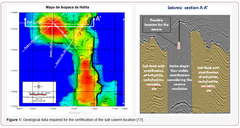
In the process of selecting potential areas for the development of salt caverns by solution mining, salt domes are selected in order to minimize the presence of interbedded non-soluble rock layers like shale and anhydrite and also to avoid the more soluble salts, carnalite and tachyhydrite as much as possible. In addition, some other criteria were established, such as the maximum depth from the top of the rock salt dome and the distance of the salt domes in relation to the oil fields. Based on interpretation of 3D seismic and 2D seismic, a cluster of salt domes 10 km away from one of the major presalt oil fields in Santos Basin was selected [18,19].
Figure 1 shows the vertical seismic section crossing a salt rock deposit that was selected for the location of the first experimental and pilot caverns to be built in ultra-deep water for CCS of the presalt reservoirs (Figure 1).
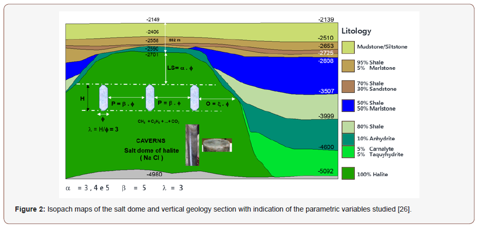
For the geomechanical design of the cavern it is necessary to make a parametric study changing the variables as indicated in Figure 2 (Figure 2).
Due to the large volume of salt dome selected, the distance between the caverns was calculated in order to eliminate the group effect so that the redistribution of stresses induced by the dissolution of one cavern will not influence the stability of the neighbor cavern in the cluster. In this condition the simulation of the structural behavior of the caverns is being conducted by the application of axisymmetric structural models. Due to the very large size of the salt dome it is possible to construct giant salt caverns. Vassalo recently presented a very elegant procedure to design giant salt caverns in shallow water. In terms of the geomechanical analysis, there is no difference in the simulations and criteria used in the design of caverns of any size [21].
For evaluating the salt caverns stability, some basic data based on the authors’ experience were adopted [21,18,19,24,25].
1. Specific weight of the sedimentary rock → 22,56 kN/m3;
2. Specific weight of the rock salt → 21 kN/m3;
3. Slab protection of rock salt at the top of the cavern → α x φ = 750 m;
4. Minimum distance between caverns to avoid interference → β x φ (between axis) = 750 m;
5. Temperature of the sea bed = 4˚C;
6. Geothermal gradient in sedimentary rock = 30˚C /1000m;
7. Geothermal gradient in rock salt = 12˚C /1000m;
8. Slenderness ratio of the cavern → λ = h/φ = 3;
9. Shape → cylindrical;
10. Size and shape of cavern→ = 450 m x 150 m;
11. Initial state of stress at the top of the cavern → σ0 = 2139 * 10 + 550 * 22,56 + 750 * 21 = 21390 + 12408 + 15750 = 49,548 kPa;
12. Maximum internal pressure of CO2 inside the cavern → 80% to 90% of the effective initial stress at the top of the cavern (Pmax) = 44,593.20 kPa;

13. The geometrical volume of the cavern is indicated in Figure 3 (Figure 3).
Figure 4 shows the cross-section of the basic geometrical data used for building the structural geomechanical model. (Figure 4).
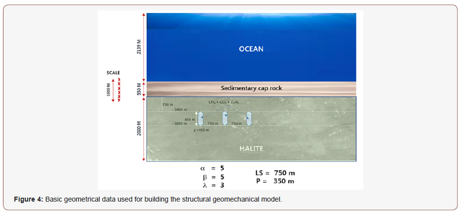
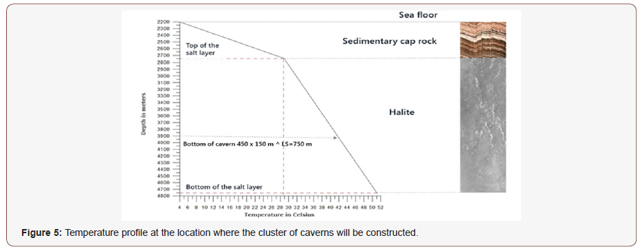
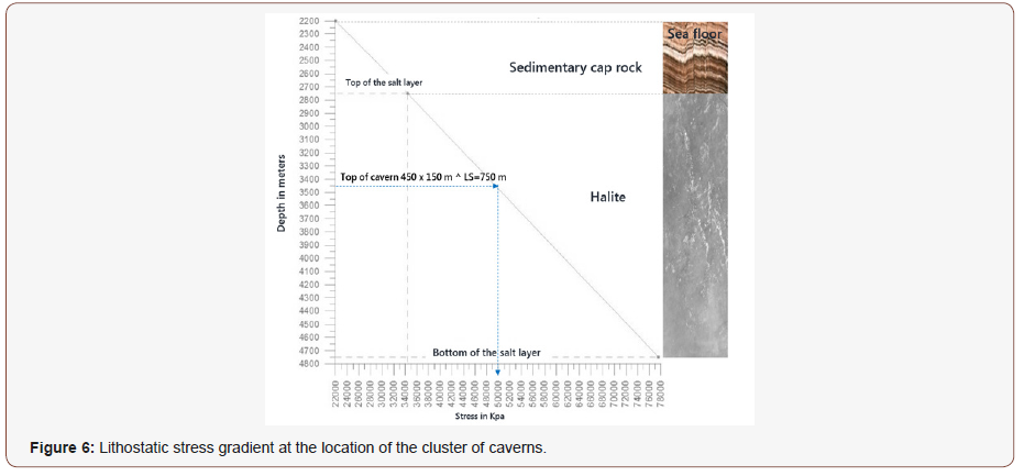
Figure 5 shows the temperature profile as a function of depth at the location where the caverns will be constructed while Figure 6 shows the lithostatic stress gradient used in the structural geomechanical simulation (Figure 5 & 6).
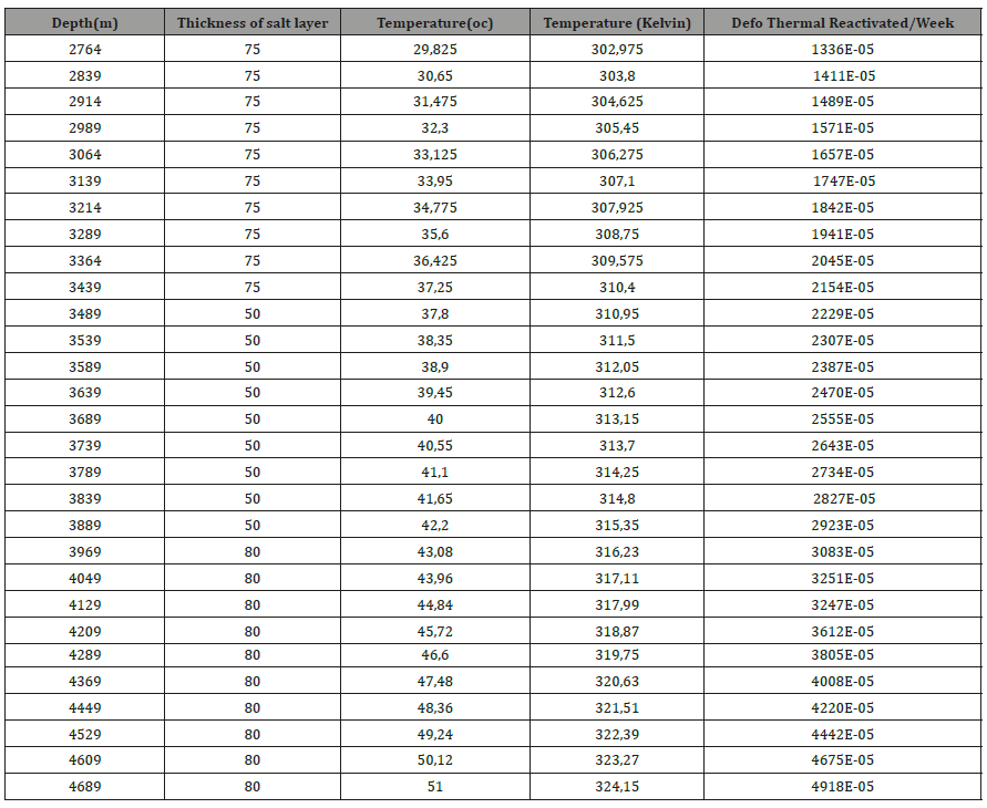
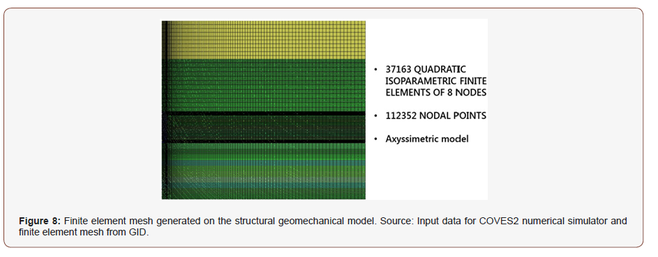
The creep strain rate of the halite, equation 3, is activated by the temperature. The rock salt layer is divided in small layers to take into consideration the variation of the temperature with depth. Figure 7 shows the structural geomechanical model used in the simulation by COVES 2 (Figure 7). On the structural geomechanical model is generated the finite element mesh, Figure 8. The creep constants are activated by temperature, equation 3, and are presented, for each layer of the structural geomechanical model in the Table 3.
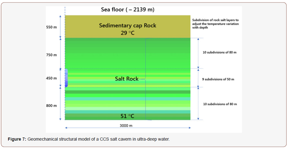
Table 3: Creep strain rate reactivated as function of the temperature in each sublayer of halite in the model.
Simulation results
COVES 2 simulated the excavation of the cavern in 9 steps of 50m each, from bottom to top of the cavern. Based on the experience of the authors in the stability analysis of salt caverns for brine production in Salgema Mineração [9], the steps of 50m is directed related to the interval time between inspections by scan sonar 3D [26]. Figure 9 shows the 9 excavation steps of 50m that was simulated by COVES 2 (Figure 9).
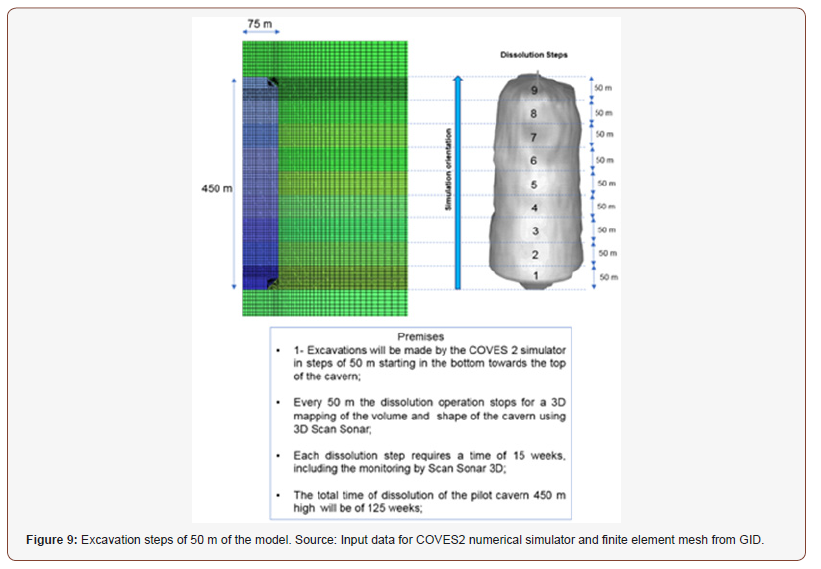
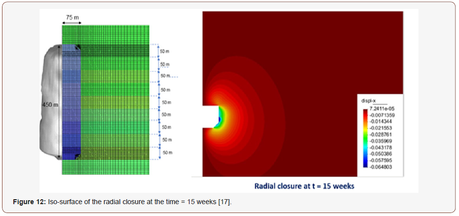
For efficient simulation of the stepwise excavation of the cavern, it is necessary to consider the dissolution time for each step of 50 m. From the alternatives studied for the construction of the cavern it is assumed the application of two wells to do the dissolution, using an injection flow rate of 140 000 barrels of sea water per day. The time to excavate each step of 50 m is approximately 15 weeks. Every 15 weeks the cavern will be monitored by scan sonar to control the diameter and shape. In case of any deviation from the predicted size and shape, in practice the stability of the cavern is reanalyzed by the structural geomechanical simulation. For the prediction of the dissolution time the SALGAS computer code was used.
Figure 10 shows how the dissolution of the giant cavern will be done. Two wells are drilled close to each other and two caverns are constructed utilizing both wells. After some time the individual caverns intercept each other and becomes only one giant cavern in the process of dissolution. During this process the caverns are monitored by scan sonar 3D in each cavern (Figure 10).
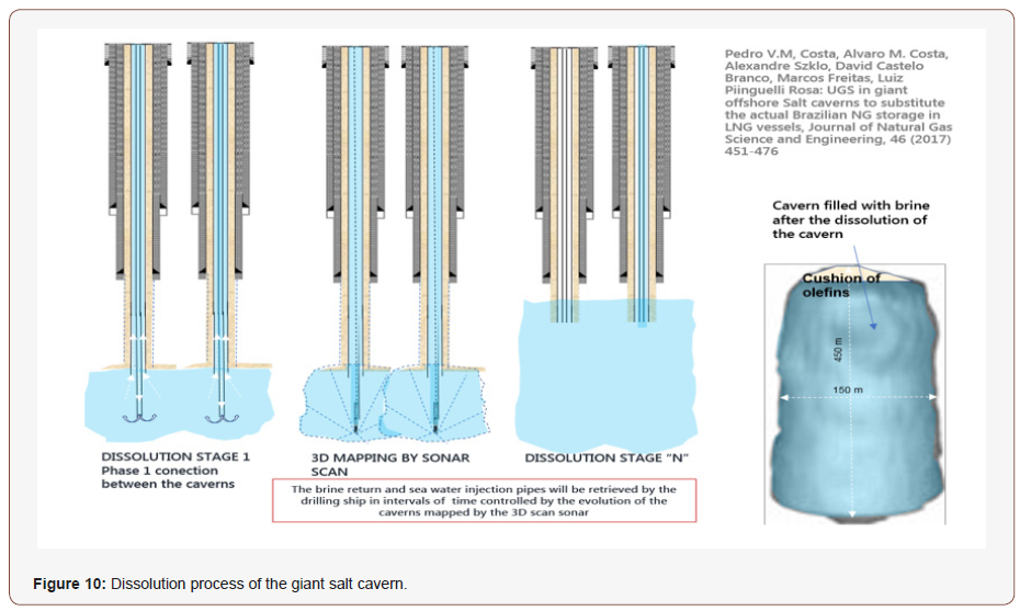
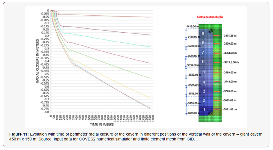
During the construction of the cavern if is detected a deviation of the size and shape of the cavern a geomechanical analysis is made to decide if it is necessary to change the position of the injection and brine return casings. COVES 2 simulates the real excavation of the cavern, step by step, in a non-linear viscoelastic basis with time, excavating the elements included in each section of 50 m, keeping the global structural equilibrium of the full model. In the excavation process, pressure of brine is decreased to induce equilibrium with the sea water column of 2139 m. Figure 11 shows the evolution with time of the radial displacements of the cavern perimeter. Each curve starts at a different time when the excavation reaches that position. Is also possible to see the effect of gas injection inside the cavern. The excavation starts from the bottom up to the top and the gas injection from the top-down to the bottom the cavern. During excavation the radial closure of the nodal point at the depth of -3851.50 m starts first and so has the larger closure with time. It is expected that the filling of each 50 m of the cavern will expend 30 weeks. So, after the cavern is finished at the time of 270 weeks the gas pressure will reach the bottom changing the creep closure velocity of the that section of the cavern. The nodal point at the depth of -3475.25 will fill the excavation effect only after 125 weeks, but it will fill the effect of the gas pressure 5 weeks later, because it is considered that it will be required 5 weeks to prepare for the gas injection inside the cavern, already considering the certification for Gas injection through the mechanical integrity test of the cavern (Figure 11).
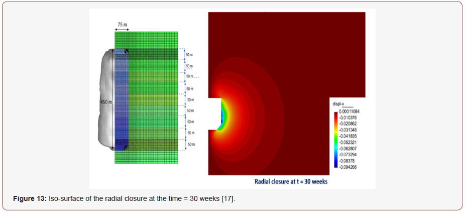
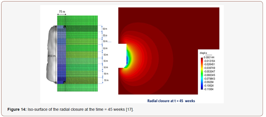
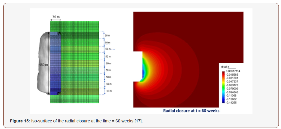
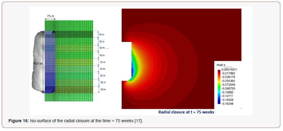
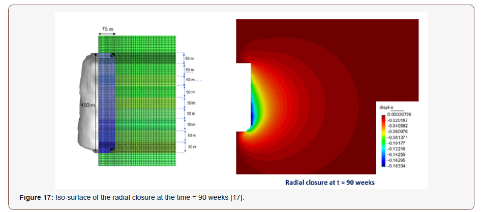
In order to understand the behavior of the cavern during the process of excavation by dissolution, the iso-surfaces of the horizontal or radial displacements are shown in Figures 12 to 19, accompanying the evolution of the excavation of the cavern in the ascending direction. As the cavern grows the fringe of displacements travels with the highest values in the same direction (Figures 12-19).
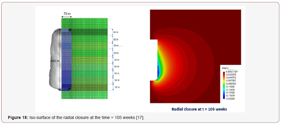
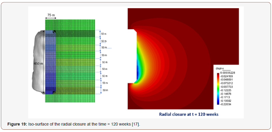
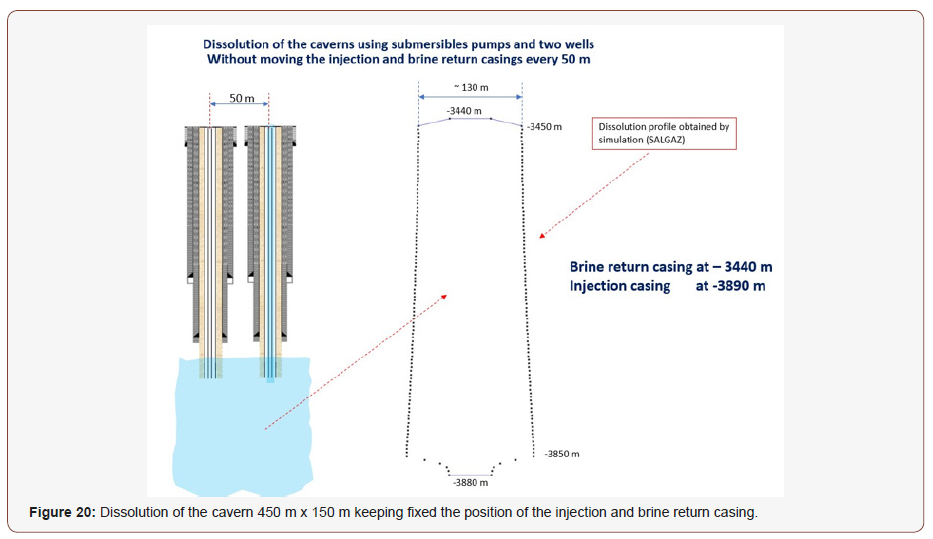
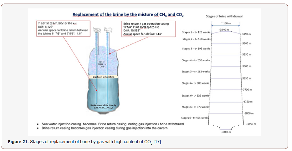
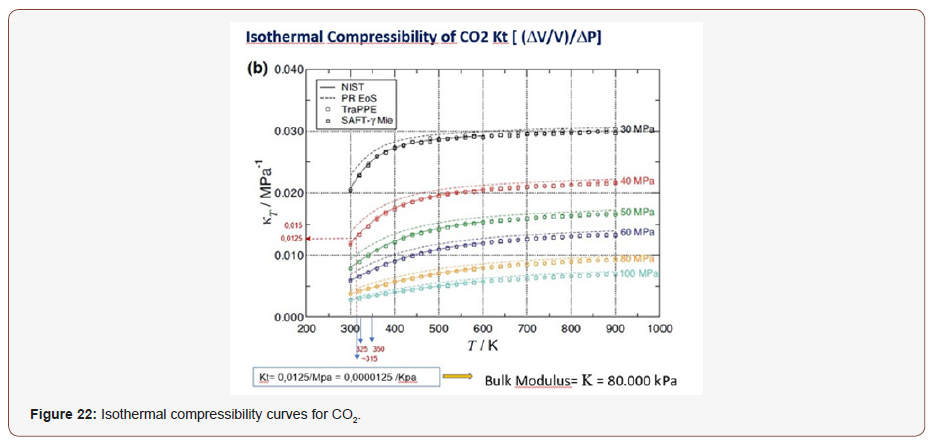
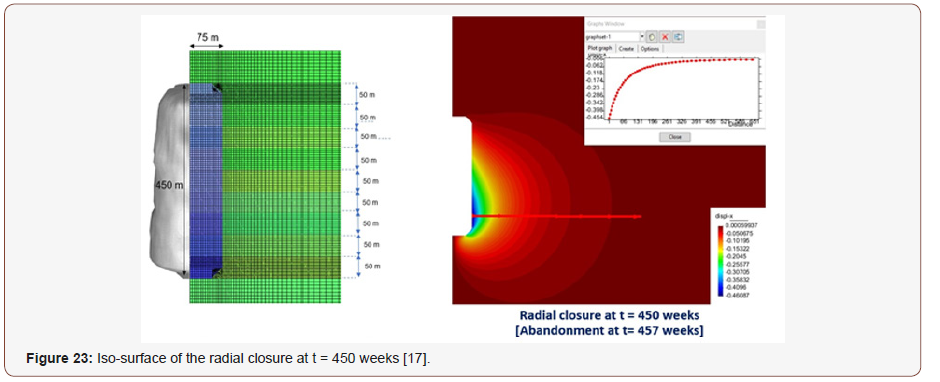
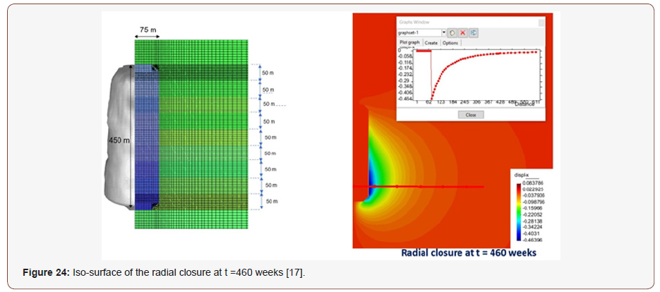
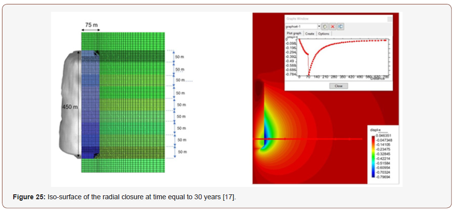
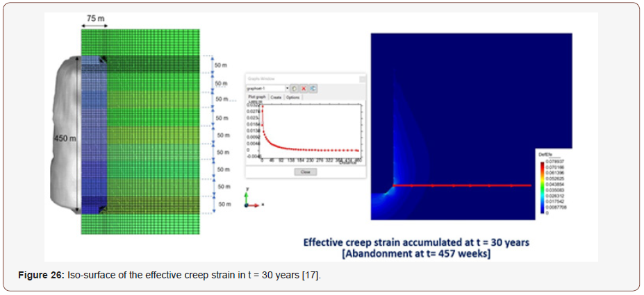
Closure measurements made in the mine shows closure at the same order of magnitude to the one obtained for the cavern for the same interval of time in the case of large excavations, like underground main silos or cluster of mining panels. If it is not necessary to change the position of the injection and brine return casings, keeping the position of the brine return casing at the top of the cavern -3440 m and the injection casing at the bottom of the cavern – 3890 m, at the same period of days 840 days or 125 weeks, it is possible to reach the cavern with 450 m of height and 150 m in diameter (Figure 20). The gas with high CO2 content is injected after 125 days, from the top to the bottom of the cavern replacing the brine with time. The gas produced in the FPSOs that is not reinject in the reservoir is filtered in the membrane equipment at the process plant. The cleaned gas, with maximum grade of 3% of CO2 is compressed through a gas pipeline to shore. The remaining gas, now with high content of CO2 will be reinjected in the reservoir for EOR and part of this contaminated gas with CO2 will be injected in the salt caverns. It is inferred that it will take 30 weeks to fill each 50 m section of the cavern, from the top to the bottom (Figure 21). For the geomechanical simulation, a time of 280 weeks to completely fill the cavern and replace the brine was assumed. At the time equal to 405 weeks the gas reaches the bottom of the cavern. At this point the closure rate of the cavern is reduced with increasing injected gas pressure, at the critical state, the creep closure deformation of the cavern with time is stabilized. It is interesting to pay attention that during the injection time the nodal points used to monitor the simulated closure of the cavern with time, continue to increase due to the creep of the halite, but with a much smaller time closure rate. It will take 52 weeks more to finish the filling of the cavern with gas at the pressure of 90% of the lithostatic pressure. At the time equal to 457 weeks the Xtree is closed. COVES 2 simulates in one run the excavation with time, the replacement of the brine by the gas with high content of CO2 and the final abandonment of the cavern. When the cavern is completely filled with gas, for the geomechanical simulation it is necessary to have the bulk modulus of the gas/CO2 at the critical state. To simulate the abandonment process, it is assumed that the cavern is filled with only CO2, due to lack of data for mixtures of gases with varying compositions. Currently laboratory tests is geared to obtain these thermodynamic parameters of gas mixtures at the University of São Paulo in Brazil. For this simulation a bulk modulus of K= 80.000 kPa. Figure 22 shows the isothermal compressibility curves presented by Cassiano, from which was calculated the bulk modulus used in the simulation of abandonment (Figure 22). Figure 23 shows the iso-surface of the radial closure at the time equal to 450 weeks, 7 weeks before the Xtree is closed. The maximum closure, as expected, occurs at the bottom of the cavern reaching 480 mm (Figure 23). Figure 24 shows the iso-surface of the radial closure at time equal to 460 weeks and figure 26 at time equal to 30 years (Figure 24 & 25). The process of scaling of the cavern wall starts when the creep strain reaches values ranging between 5% and 10% in a conventional mining, without counter pressure [21]. In this case study the maximum effective creep strain occurs only in the corner of the cavern wall, which will be smoothed over time. Figure 26 shows the iso-surface of the effective creep strain at the time of 30 years, certifying that the cavern will be kept in a very good condition even after 30 years, with 22 years of abandonment (Figure 26). The phenomenon of scaling of halite at the cavern wall is negligible which allows the use of this giant salt cavern for CCS storage in an abandonment pressure of ~450 bar.
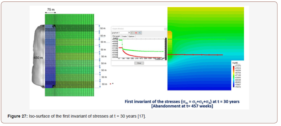
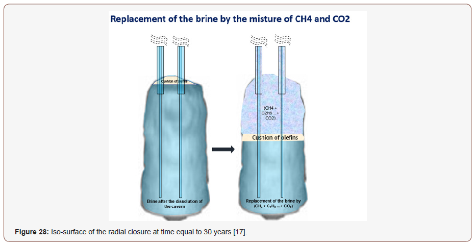
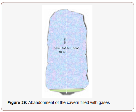
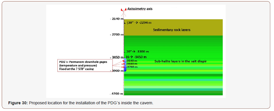
Another criterion that must be analyzed is the state of stresses of the cavern after abandonment. The cavern must always keep a reaction against the internal pressure through a closing tendency, always creating a compressive stress distribution in its surroundings, preventing the formation of micro-cracks or microfractures that may permeate gases to another formation or even to surface. Figure 27 shows the iso-surface of the first invariant of stresses {σm = (σ1 + σ2 + σ3)/3} after 30 years. The pressure inside the cavern is ~ 450 bar and in the boundary of the cavern wall ~52.500 bar, at the top of the cavern. The cavern is protected by a compressive state of stresses eliminating the possibility of gas leakage over time (Figure 27). Figure 28 shows an illustration of the brine replacement by the gases after the dissolution of the cavern (Figure 28). Figure 29 shows the final stage of the cavern at abandonment filled with gases (Figure 29). During gas injection and abandonment, the cavern must be monitored using pressure and temperature gages. Is recommended to use the conventional PDG´s (Permanent Downhole Gage), adopted by the oil and gas industry. Based on the simulation results it is possible to locate the PDG´s inside the cavern. The PDG´s will be installed in the 7 5/8” casing as illustrated in (Figure 30).
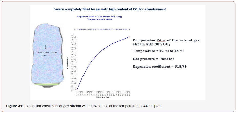
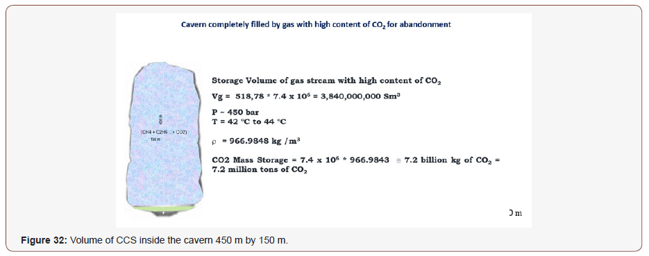
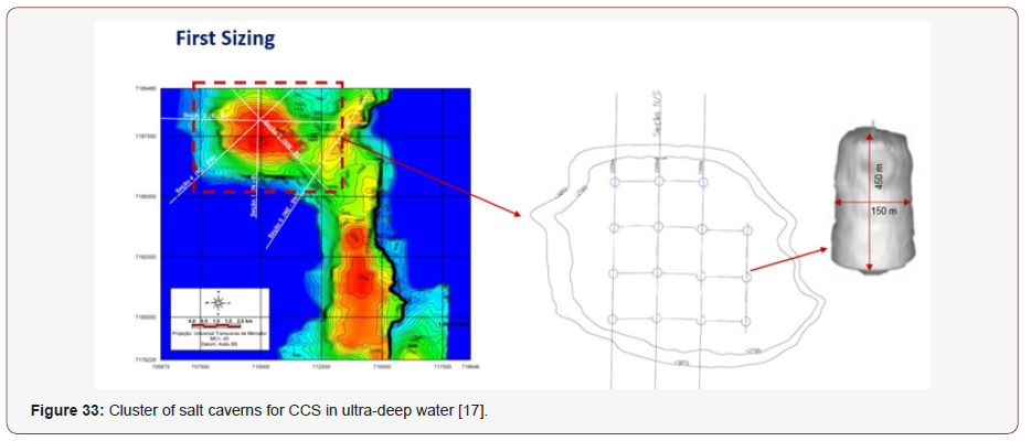
To calculate the volume of gas that is possible to be confined inside the cavern is necessary to have the expansion coefficient of the gas with different grades of CO2 for several state variables (temperature and pressure). For the state variables pressure of ~450 bar and temperature 42°C it is shown in Figure 31 the estimation of the coefficient. The curve was originally obtained for a gas with 90% of CO2 and temperature of 44°C but is still a good approximation until the laboratory tests under execution at the state university of São Paulo are concluded (Figure 31). With the interpolation of the expansion curve and using the gas pressure inside the cavern is possible to calculate the CCS volume of the cavern (Figure 32). In the salt dome selected, it is possible to construct 15 caverns, it’s shown in Figure 33. So, the total CCS storage station in ultra-deep water has the capacity to confine 108 billion kg of CO2 or 108 million tons of CO2 (Figure 33).
Logistics of the CO2 Central disposal station
Figure 34 shows a general view of the construction and operation logistics of a Offshore CCS station in deep or ultra-deep water (Figure 34).
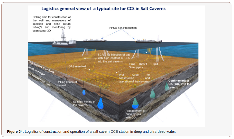
The implementation of the CO2-rich natural gas storage system in the salt caverns goes through several processes. In the first one the well is built in 3 or 4 phases. After completion of the well, it will undergo a mechanical integrity test (MIT), adopting the nitrogen interface/synthetic drilling fluid method. If the well has met all the criteria that authorize its use in the operation of the gas cavern under high pressure, the same ship that built the well will lower the seawater injection and brine return pipes. The pipes will be housed in the wellhead. The injection tube will descend to the base of the cavern. The brine return pipe will hang to the depth corresponding to the top of the cavern. From this stage, seawater injection will be made, preferably using the water injection pumps from the production vessel, the same ones used to inject water into the reservoirs, with a flow of approximately 144,000 barrels/day or about 1000 m3/hour. If the production platform pumps cannot be used for cavern leaching, high pressure submersible pumps will be used near the sea floor. The sea water in the depth of 2200 m lies at the temperature of 4°C. The higher the temperature of the injection water, the higher the rate of dissolution. In this condition, the preheating of sea water is anticipated, which, added to the temperature gain, with the geothermal gradient of the salt rock, will produce an injection water with a higher temperature, with a corresponding increase in the rate of salt dissolution and reduction of the time of construction of the cavern.
For the construction of a giant cavern with 450 m of height and 150 m of diameter will be used two identical wells with the same completion. From a certain moment the caverns of each well will intercept and will give rise to a giant cavern with 450 m of height and 150 m of diameter. Throughout the dissolution process it is expected to monitor, at each interval of 50 m, about 15 weeks of time interval, by the application of Sonar 3D, introduced into the cavern through the return pipe of the brine. At this stage the drilling vessel will be used again, which should first withdraw the water injection tube and then introduce the sonar hanging by wireline cable. Throughout the leaching process, synthetic fluid, possibly the olefin base, is injected into the annular gap between the last casing and the well to protect the top of the cavern, that is, as the fluid is pressurized the injection water cannot leach the top of the cavern due to the pressurized mattress of synthetic fluid. Once the cavern has been completed, it will undergo a mechanical integrity test (MIT-Mechanical Integrity Test) using the nitrogen/brine interface method again. In case the cavern goes through the tests of integrity and gas tightness, it initiates the injection of natural gas with CO2 through the completion tubes for operation with gas under high pressures. Both wells will be used at this stage. In order to avoid mixing the CO2 with the brine, the mattress of special synthetic fluid or hydrocarbon at the gas/brine interface will be preserved. The pressures provided by the geomechanical calculation indicate values between 350 bar and 450 bar and can reach 520 bar. BCSS type pumps may be used in each water injection tube, which now drains the brine from the cavern. The pumps will be used to aid removal of the brine, thereby preventing the breakdown of the interface synthetic fluid mattress between the brine and the gas [27-29].
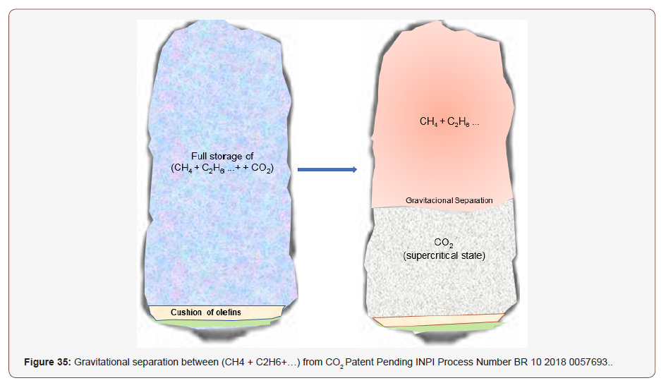
CO2-rich gas will undergo a natural process of gravitational separation between CH4 and CO2 by the density difference Figure 35. The gas will remain at the top of the cavern and CO2 at the bottom. The natural gas can be recovered and after the total filling of the cavern with CO2 the same will be conditioned for the definitive abandonment (Figure 35).
Conclusion
The creep deformation of the experimental cavern is very small because of the support from the brine and gas pressure inside the cavern and due to the low temperature within the cavern. The interval of halite between -2700 m and -3898 m is at a temperature which varies in the interval: 29°C ≤T ≤ 42°C.
The cavern can be construct by dissolution in water depth of 2140 m, through the injection of sea water, at the flowrate of 1000 m3/hour, using two wells; The separation between the two wells will be defined by the simulation of the dissolution.
Dimensions of the giant cavern certified by the geomechanical project:
1. Thickness of the safety halite slab protection between the top of the cavern and the bottom of the sedimentary cap rock: 750 m.
2. Depth of the top of cavern: -3440 m.
3. Depth of the bottom of the cavern: -3890 m.
4. Diameter: 150 m.
5. Height: 450 m.
6. Geometrical Volume of the cavern: 7.4 E+06 m3.
7. Storage volume of gas stream with high content of CO2 in one cavern: 3,840,000,000 Sm3.
8. Maximum Gas pressure expected after abandonment: 465 bar.
Based on the salt dome studied for CCS application, one cavern can store 4 billion Sm3 or 7.2 million tons of CO2. Considering the pillar size between caverns of 750 m, 5 times the diameter of one cavern, the salt dome can accommodate the construction of 15 caverns, thus providing the confinement of approximately 108 million tons of CO2.
Acknowledgment
The authors gratefully acknowledge support from Shell Brasil Petroleo and FAPESP through the “Reserch Centre for Gas Innovation - RCGI” (Fapesp Proc. 2014/50279-4), hosted by the University of Sao Paulo, and the strategic importance of the support given by ANP (Brazil’s National Oil, Natural Gas and Biofuels Agency) through the R&D levy regulation.
Conflict of Interest
No conflict of interest.
References
- Laumb JD, Glazewski KA, Hamling JA, Azenkeng A, Watson TL (2016) Wellbore corrosion and failure assessment for CO2 EOR and storage: Two case studies in the Weyburn field. Int J Greenh Gas Control 54: 479–489.
- Bachu S (2000) Sequestration of CO2 in geological media: Criteria and approach for site selection in response to climate change. Energy Convers Manag 41: 953–970.
- Wang T, Yan X, Yang H, Yang X, Jiang T, et al. (2013) A new shape design method of salt cavern used as underground gas storage,” Appl. Energy 104: 50–61.
- Shi JQ, Durucan S (2005) CO2 storage in caverns and mines. Oil Gas Sci. Technol 60(3): 569–571.
- Mohriak SM, Szatmari W, Anjos P (2008) Sal Geologia e Tectonica, First edit. Becca Edições Ltda.
- Saberian A (1984) SALGAS, User´s Manual. Solution Mining Research Institute, Clarks Summit, PA.
- Climate Change UN (2010) Carbon dioxide capture and storage in geological formations as clean development mechanism project activities.
- GATEWAY (n.d.) Gas Storage Projects UK - Gateway Storage - The Gateway Project.
- Choi YS, Young D, Nešić S, Gray LGS (2013) Wellbore integrity and corrosion of carbon steel in CO2 geologic storage environments: A literature review. Int J Greenh Gas Control (16): 70–77.
- Sminchak JR, Moody M, Theodos A, Larsen G, Gupta N (2014) Investigation of wellbore integrity factors in historical oil and gas wells for CO2 geosequestration in the Midwestern U.S. Energy Procedia 63: 5787–5797.
- Kiran R, Catalin T, Younas D, Runar N, David W, et al. (2017) Identification and evaluation of well integrity and causes of failure of well integrity barriers (A review). J Nat Gas Sci Eng 45: 511–526.
- Crow W, Carey JW, Gasda S, Brian Williams D, Celia M (2010) Wellbore integrity analysis of a natural CO2 producer. Int J Greenh Gas Control 4 (2): 186–197.
- Costa AM (1984) Uma Aplicação de Métodos Computacionais e Princípios de Mecânica das Rochas e análise de Escavações destinadas à Mineração Subterrâneas. UFRJ.
- International Center for Numerical Methods in Engineering (2018) GID: The Personal pre and post processor. Technical University of Catalonia (BarcelonaTech).
- William Carey J, Svec R, Grigg R, Zhang J, Crow W (2010) Experimental investigation of wellbore integrity and CO2-brine flow along the casingcement microannulus. Int J Greenh Gas Control 4(2): 272–282.
- Costa AM, Poiate E, Amaral CS, Goncalves CJC, Falco JL, et al. (2010) Geomechanics applied to the well design through salt layers in Brazil: A history of success in 44th US Rock Mechanics Symposium and 5th USCanada Rock Mechanics Symposium.
- Junior EP (2012) Rock Mechanics and Computing Mechanics for the project of oil wells in salt deposits. PUC-RIO.
- AM Costa, CS Amaral, EP Junior (2011) Underground Storage of Natural Gas and CO2 in Salt Caverns in Deep and Ultra-deep Water Offshore Brazil in 12th International Congress on Rock Mechanics. ISRM.
- PMC Vassalo (2013) Strategic Use of Underground Space for Natural gas Storage in Caverns opened by dissolution of salt rock. Pontifical Catholic University of Rio de Janeiro (PUC-Rio).
- Costa PRC, Melo AM (1992) Stress Analysis and Sizing of Caverns Mined by Dissolution of Halite of the Evaporitic Basin at, Alagoas State- Brazil. Houston, Texas.
- Costa PVM, Costa AM, Szklo A, Branco DC, Freitas M, et al. (2017) UGS in giant offshore salt caverns to substitute the actual Brazilian NG storage in LNG vessels. J Nat Gas Sci Eng (46): 451–476. Miranda ACO, Martha LF, Wawrzynek PA, Ingraffea AR (2009) Surface mesh regeneration considering curvatures. Eng Comput 25(2): 207–219.
- Miranda ACO, Martha LF, Wawrzynek PA, Ingraffea AR (2009) Surface mesh regeneration considering curvatures. Eng Comput 25(2): 207–219.
- Miranda ACO, Lira WWM, Marques RC, Pereira AMB, Cavalcante-Neto JB, et al. (2014) Finite Element Mesh Generation for Subsurface Simulation Models. Eng Comput pp.1–20.
- Costa PVM, Roehl D, Costa AM, Amaral CDS, Poiate E (2014) Underground salt caverns opened by solution mining for brine production and storage of natural gas. ISRM Conf Rock Mech Nat Resour Infrastructure, SBMR 2014.
- Costa PVM, Costa AM, Junior EP, Amaral CS, Pereira AMB (2015) Computer Modeling Applied in the Design of Underground Salt Caverns Opened by Solution Mining for Gas Storage in ARMA.
- Wang W and Taleghani AD (2014) Three-dimensional analysis of cement sheath integrity around Wellbores. J Pet Sci Eng 121: 38–51.
- Zhang M, Bachu S (2011) Review of integrity of existing wells in relation to CO2 geological storage: What do we know? Int J Greenh Gas Control 5(4): 826–840.
- Miranda ACO, Cavalcante-Neto JB, Marta LF (1999) An algorithm for two-dimensional mesh generation for arbitrary regions with cracks in XII Brazilian Symposium on Computer Graphics and Image Processing pp. 29–38.
- ACO Miranda, LF Martha (2017) Hierarchical Template-Based Quadrilateral Mesh Generation. Eng Comput 33(4): 701–715.
-
Alvaro M Costa, Pedro VM Costa, Julio R Meneghini, Kazuo Nishimoto, Claudio M Sampaio, et al. Hybrid Subsea CCS System-CO2 Storage in Offshore Ultra Deep-Water Salt Caverns. Cur Trends Civil & Struct Eng. 1(3): 2019. CTCSE.MS.ID.000513.
-
Geomaterial, Permeability, Porosity, Excavations, Natural Gas, Hydrocarbons, Crude Oil, Subsea CCS System, Geomechanical, Geology, Rock Salt, Salt
-

This work is licensed under a Creative Commons Attribution-NonCommercial 4.0 International License.


