 Research Article
Determination of Concrete Characteristics Using Destructive and Non-Destructive Tests
Malek Jedidi*
Department of Civil Engineering, University of Tunis El Manar, Tunisia
Malek Jedidi, Department of Civil Engineering, University of Tunis El Manar, Tunisia.
Received Date: June 09, 2020; Published Date: June 24, 2020
Abstract
Mechanical resistance and deformation are important characteristics of concrete, because they play a great role not only for the stability, but also for the durability of the structures. When concrete is subjected to the action of a rapidly increasing load, it behaves like a brittle material. On the one hand, its rupture is not preceded by significant deformations and on the other hand, its tensile strength is much weaker than its compressive strength. The tensile strength even vanishes completely if shrinkage cracks have developed. This paper presents an experimental study in order to determine some characteristics of the concrete made for the production of reinforced concrete beams. To this end, cylindrical specimens of dimensions 16 x 32 cm were prepared in the laboratory using local materials for mechanical characterization by destructive and non-destructive tests. Splitting test was carried out to determine experimentally the tensile strength of concrete. Schmid rebound hammer and compression machine were used to determine the compressive strength of concrete, as well as its longitudinal elastic modulus (Young’s modulus) at the age of 28 days. The results obtained by the various tests were compared to validate the measured values. Indeed, the concrete resistance measurements from the rebound hammer test were compared with those obtained by the compression test. Likewise, the concrete tensile strength values of the splitting test were compared with those found from the compression test.
Keywords: Concrete; Cylindrical specimens; Splitting test; Schmid rebound hammer; Elastic modulus; Compressive strength
Introduction
Concrete has now a days become the most used material in the construction of structures. Its compressive strength is the most important parameter to control in order to assess its quality [1]. In the current state, the most used method to control the quality of concrete on site, consists in carrying out destructive tests on specimens taken during the production of structural elements. However, these test specimens are not representative of structural concrete because of the difference in the conditions of placing, tightening and curing, which are the main factors affecting the strength of concrete [2,3]. The judicious choice of materials, correct implementation, the adoption of appropriate constructive arrangements play an essential role in the art of construction. However, as an important part of his activities is devoted to the problems of dimensioning of constructions, the engineer attaches particular importance to the characteristics of mechanical resistance and deformation of materials, because their knowledge is essential for him to realize constructions that are both safe and economical. In order to get around these problems, a range of non-destructive tests has been developed. These tests offer a practical and reliable means to assess the real quality of concrete in situ without affecting the structural behaviour of the elements [4-8]. However, the strength of concrete can only be assessed by these methods, but not measured. It is therefore useful to establish experimental relations between the property measured by a given test and the resistance of a test-tube or carrot of the same concrete [9]. Destructive tests are generally carried out in the laboratory on specimens made from concrete taken from the batch. The resistance must be equal or greater than the specifications required for the corresponding type of concrete. The specimens are produced during the casting of the element and the compressive strength tests are generally carried out at 7 days and 28 days.
The main disadvantages of destructive tests are that the concrete of the specimens can be different from that of the structure because the curing or tightening can be different; the resistance of the specimens also depends on their dimensions and their shapes [10]. There are several non-destructive methods carried out without physical intervention affecting the integrity of its structure. They make it possible to assess the resistance of concrete based on some of its physical properties linked to its resistance, such as hardness, the ability to transmit ultrasound and the ability to resist tearing. This work consists of verifying the quality of a concrete by measuring its compressive strength using destructive tests (crushing of the specimens) and non-destructive tests (Rebound hammer test). The modulus of elasticity of the concrete was also deduced from the compression test. These tests were developed on cylindrical 16 x 32 cm concrete test specimens made in the laboratory from local materials and for resistances reflecting current practices and environmental conditions on construction sites.
Experimental Study
Materials
Cement
The cement used was a CEM I 42.5 in conformity with the Standard NF EN 197-1 [11], produced by the Cement Company of GABES. Table 1 shows the physical and mechanical characteristics of the cement.
Table1: Physical and mechanical properties of cement.


Aggregates
Natural sand 0/4 with a finesse module equal to 2.5 was used as fine aggregates. Gravel 4/12 was used as coarse aggregates. The bulk density and absolute density of the gravel are respectively 1.40 and 2.50 g/cm3.
Mixtures
Six cylindrical specimens with a diameter of 16 cm and a height of 32 cm were prepared. The concrete was laid and tightened in three layers. The test pieces were kept in their olds and protected against impact and desiccation (wind, sun) at a temperature of 20°C ± 5°C. After 24h, they were removed from the meld and subjected to water curing at 20°C ± 2°Cor in a room at 20°C ± 2°C and a relative humidity greater than 95%. At the corresponding age, the specimens were taken out and kept in laboratory conditions until testing time. Tests and measurements were carried out in order to mechanically characterize the concrete. Three of the cylindrical specimens have undergone a compression test, these specimens are surfaced in order to present the smoothest bearing surfaces possible; the resistance of these specimens will also be estimated using a sclerometer (non-destructive test). The other three specimens were subjected to a splitting test to characterize the tensile strength of the concrete. A tensile test on the steelmaking up the beam reinforcement cage was carried out [12,13]. The surfacing of cylindrical specimens was carried out with sulphur according to standard NF EN 12390-3 [14]. It was carried out on dry and clean surfaces with a thickness of less than 5 mm. The sulphur mixture was heated to the temperature recommended by the supplier with continuous agitation in order to guarantee its homogeneity and to prevent the formation of deposits at the bottom of the container. The principle of surfacing is as follows:
1. Vertically lower one end of the cylindrical specimen into a molten sulphur mortar, previously poured onto a horizontal pan/ meld.
2. Allow the mixture to harden before repeating this operation for the other end.
3. Check that the surfacing material has adhered well to both ends of the specimen. If a surfacing layer sounds hollow, it must be removed, and the surfacing operation must be repeated.
4. Wait 30 minutes since the last surfacing before performing a compression test on the test piece.
Test Procedures
Splitting test
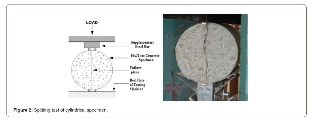
The splitting test was carried out on the cylindrical test pieces according to the standard NF EN 12390-6 [15]. This test makes it possible to determine experimentally the tensile strength of concrete. The splitting test is an indirect tensile test consisting in compressing the test piece radically (Figure 2), thus creating, by Poisson effect, horizontal tensile stresses within the material. This test works provided that the Poisson effect causes the material to rupture before the compression stresses. It is generally considered that the tensile strength of the material must be more than three times lower than its compressive strength for this test to estimate the tensile strength. This is the case for ordinary concrete where the ratio is generally around ten.
The splitting test was carried out using a hydraulic machine which generates the compressive force and which is equipped with a V-shaped support (figure 4) enabling the specimen to be entered. Supplementary steel bars are installed at the bottom of the V and on the top to avoid stress concentrations due to imperfections of the specimen. Before carrying out the test, the specimen was placed perfectly in the centre. Indeed, if the load is offset, the test can give aberrant and non-exploitable results. We can also check after rupture that the two parts of the split specimen are well symmetrical, and of the same dimensions. From the maximum failure load P, the tensile strength of the concrete fact was calculated using the following formula (Eq.1):

Where P: Maximum failure load (KN); D: Diameter of concrete cylinder (m); L: Length of concrete cylinder (m)
According to Fig. 2, it can be seen that approximately 80% of the section of the specimen is subjected to tensile stresses. The crack of the cylinder is initiated in the centre of it in the plane of application of the forces. This gives a plane rupture facies, except in the areas of application of the load, where irregularities are observed due to localized compression areas. These areas are located at the test/ press interfaces: they therefore directly undergo the compression stresses applied by the machine.
Schmidt rebound hammer test
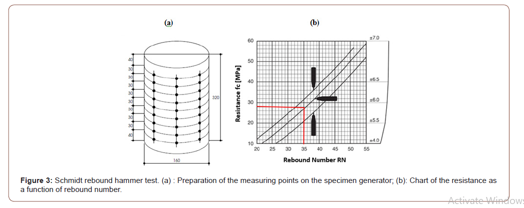
The rebound hammer test was carried out to determine the compressive strength of the cylindrical specimens at the age of 28 days according to the standard NF EN 12504-2 [16] and EN 12309- 3 [14].This non-destructive test is, as their name suggests, can be used in preliminary studies for the rehabilitation of a building without the need to core the structure. The results of this non-destructive test were then compared to the results obtained by the destructive test (Compressive test). Concrete is a porous and non-homogeneous material. Several measurements were made on the lateral surface of the cylindrical specimens. In fact, on each generator of the cylindrical specimen, 9 measurement points spaced 30 mm apart were chosen (Figure 3(a)). The specimen was kept between the two plates of the testing machine under a force of the order of 10KN. Then, the rebound number was measured by the rebound hammer at each measurement point. The operating principle of the rebound hammer consists in projecting a ball on the surface to be tested using test energy and reading the rebound height of the ball; the measurement can be read directly on the graduated part of the sclerometer. The initial rebound kinetic energy is given in the rebound hammer as a measure to estimate the stiffness of the concrete in order to deduce its compressive strength fc. After several tests on the three generatrices of the specimen, the estimate of the compressive strength fc is based on the median value of the rebound RN and the position of the sclerometer during the measurement (horizontal as here, vertical head up or below) (Figure 3(b)).


Compressive strength test
The compressive test of cylindrical specimens was carried out in order to determine the compressive strength of concrete, as well as its longitudinal elastic modulus (Young’s modulus) according to the requirements of NF EN 12390-3 [14] and NF EN 12390-13 [17]. The compressive test consists in applying a compressive stress on the cylindrical specimens placed vertically. The specimens were previously surfaced with sulphur to minimize friction with the press plates. Homogeneous stress was applied throughout the section during the test. The risk of stress concentrations appearing, which can cause premature rupture of the specimen, is thus limited. Surfacing thus ensures the reproducibility and reliability of the test and, above all, reduces the hooping effect. This effect is due to the decrease in the Poisson effect caused by friction between the press plates and the specimen. The measurements during the compression test were carried out by three strain gauge sensors in the strain gauge cage (Figure 11). The test piece was installed in the cage still fitted with spacers temporarily assembling the two rings of the cage. The spacers guarantee the initial distance between the planes passing through the needles. The relative displacement between these planes was measured by the three displacement sensors, making it possible to calculate the average deformation over the measured height. The test isan effort-driven and remains in the elastic range of concrete without destroying the specimen. The identification of the Young’s modulus of the material is based on the elastic domain, where the evolution of the stresses is linear with respect to the deformations and obeys Hooke’s law given by the following formula (Eq.2):

Where σ : Stress to which the material is subjected ; ε : Deformations of the material ; EC : Young’s modulus.
In order to ensure that it is within the range of validity of Hooke’s law, Young’s modulus has been calculated over the range of constraints limited by 0 and 0.3σmax. The average longitudinal deformation was calculated using the displacement sensors. The evolution of the force applied by the press on the material as a function of its longitudinal deformation was also measured in order to draw the stress/deformation diagram of the concrete. Once the elastic modulus has been estimated, the diagram has been drawn to failure.
Experimental Results
Splitting test
Table 2 gives the results of the splitting test carried out on the three cylindrical specimens at the age of 28 days. The average tensile strength is equal to 2.80 MPa.
Table2: Physical and mechanical properties of cement.

Different types of damage have been observed in the rupture sections of cylindrical specimens:
1. Aggregate failure;
2. Breakage of cement paste;
3. Loose aggregates at the interface between cement paste and aggregates
It is also observed that the interior of the section of the specimen is still wet beyond 1 cm in thickness. The concrete at the age of 28 days at the time of the test has therefore not finished its hydration or drying. The complete drying of a concrete is a very slow diffusive process, approximately twenty-five years are necessary to obtain the water balance of a specimen of this type in an environment having a relative humidity of 35%. However, this property gives concretes one interesting characteristics. In fact, when setting, it is estimated that for ordinary concrete about 15% of the cement used is not hydrated. This percentage increases for high performance concretes. This cement will be gradually hydrated over time, thanks to the water transfers within the material. This phenomenon gives concrete its self-healing property. Opening a crack can allow water to gradually penetrate and hydrate the still an hydrous cement.
Schmidt rebound hammer test
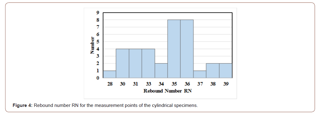
From the results presented in figure 4, the median value of the rebound number RN is equal to 35. The measurements are made with a horizontal sclerometer, the curve of the chart to be considered for reading the resistance is therefore the central curve, which gives fc = 28 MPa. (Figure 3(b)).

Table3: Quality of Concrete for different values of rebound number [19].

After determining the rebound number RN for the cylindrical specimens, the quality of the concrete was evaluated by referring to Table 3. Since the rebound number is between 30 and 40, it is therefore a good quality concrete. In general, the rebound number increases as the strength of concrete increases and is also affected by a several parameters (type of cement, type of aggregate, surface condition and moisture content of the concrete, curing and age of concrete, carbonation of concrete surface) [18].

Compressive strength test
Figure 5 shows the evolution of the stress as a function of the deformation in the elastic range during the test on the cylindrical specimen.
Regression results in Eq. 3 shows that the stress σ is linear correlated with the deformation ε. The correlation coefficient (R2) is almost 100%. The young’s modulus is then equal to 36500 MPa.

The compressive strength of the different cylindrical specimens are respectively 31, 28 and 30 MPa. The average resistance value of the concrete is therefore fc = 30 MPa.
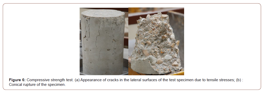
During loading of the specimen, numerous cracks due to the tensile stresses developed by the Poisson effect appeared on its lateral surface (Figure 6). As the concrete has a tensile strength much lower than its compressive strength, the radial deformations (less significant than the longitudinal deformations) have generated tensile stresses thus causing the appearance of the first cracks. These tensile stresses we recreated at the aggregate/cement paste interfaces. During loading, the cracks propagate gradually leading to the rupture of the specimen in compression. During the test, the specimens were deformed by widening halfway due to a hooping effect. Indeed, the deformations at the bases of the specimen are hampered due to friction with the platens of the press. The possible modes of failures of cylinder test are shown in Figure 7. The most usual failure is by spitting and shear as shown in Figure 7 (c) [19].


Discussion
According to Euro code 2, the tensile strength of a concrete can be estimated from its compressive strength by the following formula (Eq.4):

Where fc = 30MPa (The average resistance value of the concrete determined by compression test).
By applying Eq. 4 and Eq. 5, we find a tensile strength fct = 2.35 MPa; (fck = 22 MPa).
The average value of tensile strength determined by the splitting test is fct = 2.8 MPa. This value is much higher than that calculated by Eq. 4 (2.8 MPa > 2.35 MPa) which corresponds to a relative deviation of about 20%. Despite this difference, the two tensile strength values are of the same order of magnitude; the results of the splitting test therefore seem consistent although the traction is applied indirectly.
In the case of ordinary concrete, the value of the tensile strength is estimated to be close to 10% of its compressive strength. In our study, this ratio is calculated as follows (Eq. 6):

From the result of the resistance ratio calculated by Eq. 6, it is clear that it is an ordinary concrete without the addition (9.3% ≈ 10%). The value of the compressive strength of the concrete determined by the rebound hammer test is fc = 28MPa and that determined by the compression test is fc = 30MPa. The two tests, therefore give similar values, the relative difference observed is 7%.
Conclusion
The present paper presented the results of an experimental study carried out on cylindrical concrete specimens (16 x 32 cm) prepared in the laboratory. The compressive and the tensile strength have been determined using destructive and non destructive tests. From the experimental results, the following conclusions were drawn:
1. The average tensile strength of cylindrical specimens determined by splitting test at the age of 28 days is equal to 2.80 MPa.
2. The compressive strengths of the concrete determined by the rebound hammer test and the compression test are respectively 28 and 30 MPa.
3. The value of the Young’s modulus deduced from the compression test is equal to 36500 MPa.
From the tests carried out on the cylindrical specimens, it is noted that the concrete tested is of good quality and of sufficient strength to be used in the manufacture of beams. The rebound hammer represents a good alternative to the compression test to quickly determine the characteristics of a material in situ. The non-destructive rebound hammer test can be very useful in cases of renovation, where the characteristics of existing materials are often overlooked, and where coring is difficult (risk of structural instability). The compression test remains essential to accurately characterize the resistance of a material, as well as its modulus of elasticity.
Acknowledgement
None.
Conflict of Interest
No conflict of interest.
References
- Neville AM (2011) Properties of Concrete, Edition Enrollers, Paris, France.
- Celaya M, Nazarian S, Yuan D (2009) Comparison of field and laboratory strengths of concrete slabs, International Symposium Non-Destructive Testing in Civil Engineering, France
- Delacour J, Geoffray JM (2004) Results and recommendations of the national Calibe project: Mastering the quality of concrete, Presses of the National School of Bridges and Roads, Paris, France.
- Bin Ibrahim A N, Bin Ismail P, Forde M (2002) Guidebook on non-destructive testing of concrete structures, International Atomic Energy Agency, Vienna.
- Jedidi M (2020) Evaluation of the Quality of Concrete Structures by the Rebound Hammer Method. Current Trends in Civil & Structural Engineering, 5(5).
- Breysse D (2012) Non-destructive evaluation of concrete strength: a historical review and a new perspective by combining NDT methods". Construction and Building Materials 33: 139-163.
- Jedidi M, Machta K (2014) Destructive and Non-destructive Testing of Concrete Structures. Jordan Journal of Civil Engineering 8(4).
- Jedidi M, Abroug A, Moalla B, Benjeddou O (2017) Non-destructive Testing for the Diagnosis and Repair of a Reinforced Concrete Building. International Journal of Architecture, Engineering and Construction 6(1): 20-28.
- Breysse D, Larget M, Sbartai, Lataste J, Balayssac J (2009) Quality of NDT measurements and accuracy of concrete physical properties, 7th International Symposium on Non-destructive Testing in Civil Engineering, Nantes, France 8p
- Qasrawi HY (2000) Concrete strength by combined non-destructive methods simply and reliably predicted, Cement and Concrete Research 30(5): 739-746.
- NF EN 197-1: Cement-Part1: composition, specifications and conformity criteria for common cements, AFNOR 2012.
- NF EN 196-1: Methods of testing cement -Part1: Determination of strength, AFNOR 2016.
- NF EN 196-6: Methods of testing cement - Determination of fineness, AFNOR 2018.
- EN 12309-3: Testing Hardened Concrete- Part 3: Compressive Strength of Test Specimens, AFNOR 2003.
- NF EN 12390-6: Testing hardened concrete: Tensile splitting strength of test specimens, AFNOR 2009.
- NF EN 12504-2: Testing Concrete in Structures. Non-destructive Testing. Determination of Rebound Number, AFNOR 2012.
- NF EN 12390-13: Testing hardened concrete - part 13: determination of secant modulus of elasticity in compression, AFNOR 2014.
- Ferhat A, Mehmet S (2010) Correlation between Schmidt Hammer and destructive compressions testing for concretes in existing buildings, Scientific Research and Essays 5(13): 1644-1648.
- Hitesh P, Dhaval K, Rupali T (2015) Comparative Study of Effect of Curing on Compressive Strength of Concrete by Using NDT & DT, International Journal for Science and Advance Research In Technology 1(6).
-
Malek Jedidi. Determination of Concrete Characteristics Using Destructive and Non-Destructive Tests. Cur Trends Civil & Struct Eng. 6(1): 2020. CTCSE.MS.ID.000627.
-
Concrete, Cylindrical specimens, Splitting test, Schmid rebound hammer, Elastic modulus, Compressive strength
-

This work is licensed under a Creative Commons Attribution-NonCommercial 4.0 International License.


