 Review Article
Evaluation of the Quality of Concrete Structures by the Rebound Hammer Method
Malek Jedidi1,2*
1Higher Institute of Technological Studies of Sfax, Department of Civil Engineering, Sfax, Tunisia
2University of Tunis El Manar, National Engineering School of Tunis, Civil Engineering Laboratory, Tunis, Tunisia
Malek Jedidi, University of Tunis El Manar, National Engineering School of Tunis, Civil Engineering Laboratory, Tunis, Tunisia.
Received Date: April 23, 2020; Published Date: May 13, 2020
Abstract
The quality problems encountered in concrete structures appear at different stages of the construction of works, it is for this reason that for a long time there has been an increased demand for more precise and, at the same time, more flexible methods of concrete quality assessment. This paper presents some notions concerning the Schmidt rebound hammer test which is one of the non-destructive methods most used for the recognition of the condition of building structures. This test is quick and easy, it makes it possible to control the quality of the construction and to indirectly measure the compressive strength of concrete in situ. The rebound hammer calibration procedure was detailed on an example by presenting the different steps. The influence of several factors affecting the rebound hammer test, whether related to the properties of concrete or otherwise, was were presented. Indeed, Surface texture, concrete humidity, type of aggregates, cement type and carbonation of the concrete surface are parameters which strongly influence the results of Schmidt rebound hammer test.
Keywords: Concrete; Schmidt rebound hammer; Non-destructive; Compressive strength
Introduction
The quality problems encountered in concrete structures appear at different stages of the construction of works, it is for this reason that for a long time there has been an increased demand for more precise and, at the same time, more flexible methods of concrete quality assessment. Concrete structures generally perform fairly well even when exposed to a harsh environment. However, statistics show that certain difficulties arise during the construction period for various reasons; the most frequent is an insufficient resistance of the concrete to compression. Indeed, following the findings and expert reports carried out on reinforced concrete structures after natural disasters, it was noted that one of the major factors behind the scale of disasters is due to non-compliance building standards. The quality of the concrete put in place is not in accordance with that mentioned by laboratory crushing tests. Control by destructive tests requires the preparation or the taking of samples and cannot be carried out at 100% or at least on a significant sample. In addition, the sample taken is not always representative of the concrete of the actual structure. To address these problems, a range of in situ tests called “non-destructive tests” has been developed to complement the destructive tests. The non-de structive testing of concrete is of great scientific and practical importance. The subject has attracted the growing attention of several researchers in recent years, particularly the need to characterize the quality of damaged constructions made of concrete [1-4]. Nowadays, the most widely used non-destructive test to measure the surface hardness of concrete is the Schmidt sclerometer (Schmidt rebound hammer), [5]. Originally developed in 1050 by Swiss engineer Ernest Schmidt and presented to the Swiss federal testing and experimental Institute of Zurich ; the device will then be developed by integrating a graduated scale to read the rebound index directly [6-8], and using a single spring instead of two for simplicity and convenience [9,10].
The rebound hammer test evaluates the compressive strength of concrete by the rebound of an elastic mass. Despite the fact that the Schmidt rebound hammer test is very simple to perform, it has several disadvantages:
1. It is sensitive to local variations in concrete. For example, if the hammer head is pressed against an aggregate, the rebound index will be higher than if it is located on a vacuum.
2. The head of the hammer must always be perpendicular to the surface of the concrete, which is not easily achievable. In addition, the position of the hammer relative to the vertical will influence the rebound index, gravity acting on the movement of the mass of the hammer.
Introduced and developed by Proceeq SA, founded in 1954; several hundred thousand copies of the original Schmidt rebound hammer have been manufactured and used around the world [11]. It I s undoubtedly the most commonly used device for non-destructive testing (NDT) to quickly assess the condition of a concrete structure. Over the years, its application has extended to rock tests and hardness tests of paper reels. PROCEQ also manufactures a wider range of hammers to adapt to virtually all in-situ testing applications including the original Schmidt hammer type N and L, recording type NR and LR, digital types ND and LD DIGI- SCHMIDT. The latest PROCEQ Silver Schmidt model (instrument made in Switzerland) offers unprecedented benefits to users. The new instrument has unrivaled ease of use; easy reading of the rebound index and higher accuracy, as well as an extended measurement range. A number of benefits have been incorporated such as automatic correction of impact direction based readings eliminating the need to refer to impact direction conversion curves. The robust lightweight device also allows automatic corrections for carbonation. The data collection and processing of the test results of this equipment comply with the main industry standards.
The Ultrasonic Pulse Velocity Test
Physical operating principle
The rebound hammer test is intended to measure the surface hardness of concrete and there is an empirical relationship between the compressive strength of concrete and the rebound index which is a code composed of a letter (giving a indication of the quality of the concrete) and a number (giving indication of the compressive strength). The hammer has an approximate mass of 1.8 kg and is suitable for laboratory and site tests. A counterweight controlled by a spring moves on a plunger in a protective tube (Figure 1), the mass is projected against the surface of the concrete by the spring and the rebound distance is measured on an arbitrary scale marked from 10 to 100 [12,13] (Figure 1).
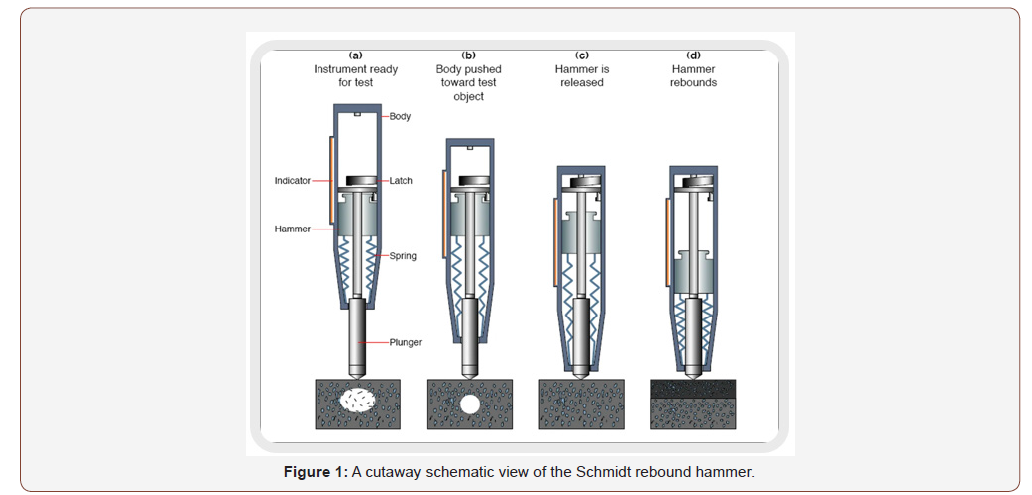
The Schmidt rebound hammer, made of a steel hammer compressed by a spring, which, after release, projects a steel percussion rod in contact with the concrete surface. The speed of movement of the hammer produced by the spring must be constant and reproducible. The rebound of the steel hammer relative to the steel percussion rod or other rebound values must be measured on a linear scale integral with the frame of the instrument. The surface on which the test is carried out may be horizontal, vertical, or at any other angle (Figure 2). A correction must be made to the values read to take account of the angle of inclination of the strike. The correction to be made depends on the model of the sclerometer, it is only necessary that the device is calibrated to the position where it will be used.
The calibration can be carried out with cylindrical specimens of 16 × 32 cm, made with the same concrete composition as that of the structure. According to ASTM-C805, the rebound index depends directly on the hardness of the surface; the energy absorbed by concrete is linked to its compressive strength.
Calibration and interpretation of results
There is a fairly large disagreement between researchers concerning the precision with regard to the evaluation of the compressive strength of concrete from the values of the rebound index [14,15]. DIN 4240 was the first report published in 1962 concerning the use of the schmidt rebound hammer test and the interpretation of results by proposing correlation curves. Other researchers then began to establish correlations between the rebound index and the compressive strength of concrete and it became obvious that there is no single relationship linking these two parameters [16], this which led to the recommendation to establish and develop correlation curves each time using test pieces from the same concrete composition as that of the structure in question. The rebound index is very much influenced by the intrinsic properties of concrete depending on whether the impact of the test occurs on the aggregate or on the cement paste.

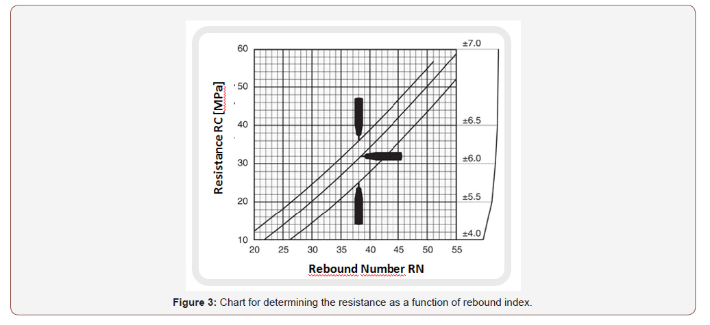
Thus ASTM 805 requires that a series of 10 measurements must be made in a limited area around the same point for the same test. A first correction must be made to take into account the direction of the impact (horizontal, vertical) and thus be able to call the curve connecting the rebound index to the compressive strength of the concrete as shown in Figure 3.
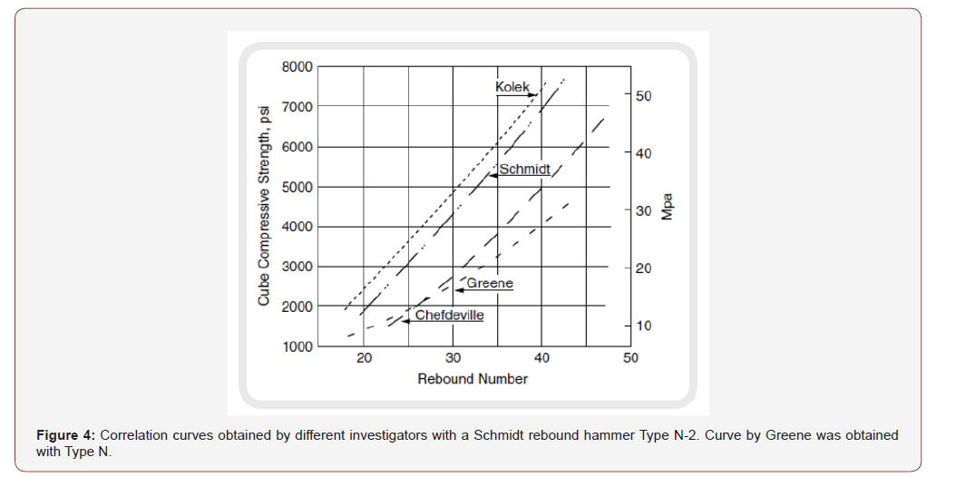
For many countries, the correlation and calibration curves are based on the 150 × 150 × 300 mm3 test specimen crush test. Another important factor influencing the reading of the rebound index is the carbonation of the concrete surface; its value can be 50% higher than when you have a normal surface. The correction factors were proposed by [15] as well as in the Japanese and Chinese guidelines, but their values are very different from each other. The only effective way to take this effect into account is calibration and correlation based on crushed carrots extracted from the work itself. Many other factors are recognized as influencing the rebound index [17]: the humidity, the texture of the surface, the type of aggregate, so that it is unlikely that the calibration curves provided and provided by the industrial manufacturers of sclerometers will be of any use. This is why the standard Pr EN 13791 has chosen a different approach which proposes a basic curve and recommends a calibration process. This involves shifting this curve as a function of the results of the values of the compressive strengths of the cores from the construction under investigation. Figure 4 shows four calibration curves obtained by research workers in four different countries [16]. It is important to note that some of the curves deviate considerably from the curve supplied with the hammer (Figure 4).
Schmidt rebound hammer calibration procedure
It is necessary to establish a relationship between the rebound indices (indirect measurements) and the results of compressive strength on test specimens or cores (direct tests). The operating mode presented below is partly defined in standard Pr EN 13791. The estimation of the compressive strength from the Schmidt re bound hammer is carried out on a calibrated curve established from the basic curve representative of a large number of test results. The base curve represents the lower limit curve of the expected test results. It is combined with a safety correction factor Δf determined during calibration on a specimen.
Step 1 : specimen preparation
Preparing (or coring) 9 specimens representative of the concrete which is desired to estimate the resistance. The specimens are tested at different ages.
Step 2 : Determination of the median rebound index and the compressive strength
Determine for each specimen its value at the Schmidt rebound hammer and its compressive strength according to the following methods:
1. Draw three generators over the full height of the cylindrical specimen or draw four medians over the full height of each side of the cubic specimen (in the compression test position)
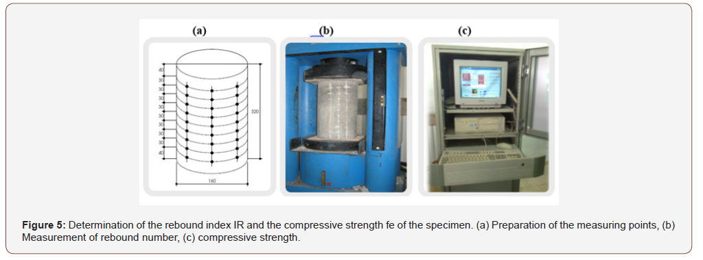
2. On each of the generators of the specimen, identify the measurement points spaced 30 mm apart, the extreme points in front of themselves being at least 30 mm from the two ends of the test piece. For a 160 x 320 mm cylindrical specimen for example, it is possible to consider 27 measurement points (Figure 5(a)) ;
3. Prepare the specimen according to standard NF EN 12390-3 ;
4. Maintain the specimen between the two plates of the testing machine under a force of the order of 10KN (Figure 5(b)) ;
5. Take rebound measurements with the Schmidt rebound hammer at each measurement point and determine the median IR value of these measurements
6. Determine the compressive strength of the specimen (fe) (Figure 5(c))
Step 3 : Determination of the average difference δfm
Determine the average difference δfm between the measured values and the basic curve according to the following methods:
1. Transfer the values (IR, fe) obtained for the 9 specimens to the graph of the base curve;
2. Calculate for each of the 9 specimens the difference δf between the measured value and the basic curve by the following relation (Eq. 1):
δf = fe − fR (1)
Where fe : Compressive strength of the specimen ; fR : Initial value of the resistance obtained on the base curve
3. Calculate the mean value (δfm) of the 9 values of (δf) and the standard deviation (s).
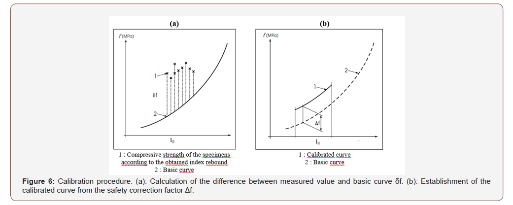
Step 4 : Determination of the safety correction factor Δf
Determine the safety correction factor Δf (Figure 6) to be applied to the basic curve to obtain the calibrated curve according to the following relation (Eq. 2):
Δf = δfm − k.s (2)
Where δfm : Mean value of the 9 values of the difference δf between the measured value and the basic curve : s : Standard deviation ; k : Factor established for 9 specimens (k=1.67) (Figure 6).
The low estimate of the compressive strength from the rebound index is obtained on the calibrated curve. 95% of true compression resistances are greater than the estimated resistances on the calibrated curve with a probability of 75%. The calibrated curve is valid within an interval of ± 2 units outside the range of rebound results obtained during calibration and for a concrete representative of that used during calibration.
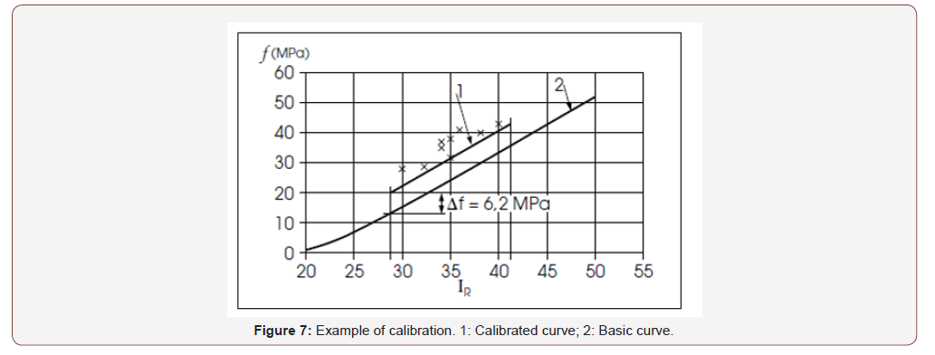
Example of calibration of a Schmidt rebound hammer
Table 1 gives the values of the compressive strength and the median rebound index produced on 9 concrete specimens. For each surface area tested, the IR rebound index retained corresponds to the median of the individual index values. The index for several constituent zones is determined by calculating the average of the median values. By applying Eq. 1 and 2, we find the following values:
1. The mean value of the 9 values δfm = 10.4 MPa
2. The standard deviation s = 2.5 MPa
3. The safety correction factor Δf = δfm – 1.67s = 6.2 MPa (Table 1)
Table 1:Values of the compressive strength and the median rebound index.

The calibrated rebound hammer curve (low estimate of resistance from the rebound index) is valid for rebound indices between 28 and 42 (Figure 7).
Factors Influencing the Rebound Hammer Test
Despite the fact that the rebound hammer test is simple, quick and inexpensive to check concrete, it has certain drawback and has certain limits which can considerably affect its reliability. The rebound hammer test is therefore affected by various factors, the most interesting of which are:
Surface texture
The texture of the surface is of great importance for the accuracy of the results. The rebound index is reduced by the roughness of the surface, researchers like Kolek and Greene [9,12] recommended polishing the surfaces before the test.
Dimension, shape and rigidity of the element to be tested
For elements of small dimensions (beam, specimen), any movement of the element causes a decrease in the value of the rebound index. To remedy this, the element to be tested must be rigidly maintained.
Age of the item to be tested
Zoldners and Victor [18,19] demonstrated that for equal resistances; higher values of the rebound index are obtained for a 7-dayold concrete than for a 28-day-old concrete.
Concrete humidity
The degree of saturation of the concrete has a decisive effect on the value of the rebound index Zoldners and Victor [18,19] have shown that tests on concrete specimens in a saturated state gave values of l rebound index 5 points less than when the test pieces were tested in a dry state.
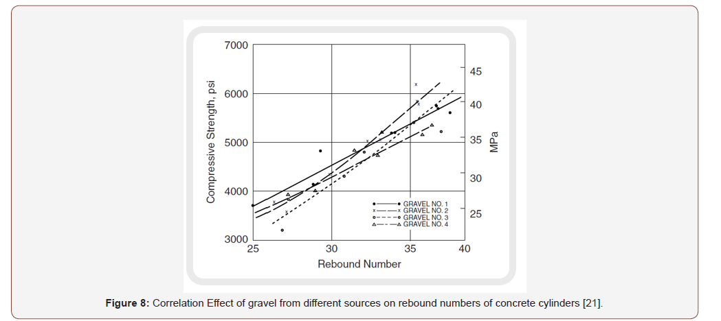
Type of aggregates
Klieger et al. [20] Have shown that for equal values of compressive strength, concrete made with crushed aggregates gives rebound index values of 7 points lower than for concrete made with natural aggregates.
Figure 8 shows a study made for 4 different types of aggregates for the manufacture of test tubes for the sclerometer test (rebound hammer).
Cement type
According to [16], concrete made with aluminous cement has a value of compressive strength 100% higher compared to concrete made with ordinary cement, which necessarily leads to high values of the index of rebound.
Carbonation of the concrete surface
The carbonation surface seriously affects the rebound hammer tests. In old concrete, the thickness of the carbonation surface can reach a few millimetres; in this case the values of the rebound index can be 50% higher than for a concrete surface without carbonation.
Conclusion
The evaluation of the compressive strength of concrete in situ by means of non-destructive testing using the rebound hammer test is an effective means to ensure effective compaction and good cure with a better indication of the concrete finish. Indeed, it is possible to save time on the speed of execution of the total construction program since the precise evaluation of the resistance allows a ‘turn-around’ of the formwork which will allow increasing the speed, reducing the cost of construction and improve quality. The rebound hammer test is simple, quick and inexpensive to check the quality of concrete, but it has certain drawback and limits which can considerably affect its reliability. The use of the rebound hammer only allows an estimate of the strength of the concrete or its regularity. Nevertheless, in the context of factory production monitoring, the measurement of the rebound index remains a good indicator, when it is the subject of a satisfactory correlation. The results of the rebound hammer test are influenced by factors such as the Surface texture, concrete humidity, type of aggregates, cement type and carbonation of the concrete.
Acknowledgement
None.
Conflict of Interest
No conflict of interest.
References
- Jedidi M (2018) Evaluation of the concrete quality using destructive and non–destructive tests. MOJ Civil Eng 4(4): 219-223.
- Breysse D (2012) Non-destructive evaluation of concrete strength: a historical review and a new perspective by combining NDT methods. Construction and Building Materials, 33: 139-163.
- Jedidi M, Machta K (2014) Destructive and Non-destructive Testing of Concrete Structures. Jordan Journal of Civil Engineering 8(4).
- Jedidi M, Abroug A, Moalla B, Benjeddou O (2017) Non-destructive Testing for the Diagnosis and Repair of a Reinforced Concrete Building. International Journal of Architecture, Engineering and Construction 6(1): 20-28.
- Szallagy K (2013) Rebound surface hardness and related properties of concrete. thèse de doctorat, universite de Budapest.
- Schmidt E (1950) The concrete test hammer (der béton-ru.fhammer) Schmeiz.Bauz (Zurick) 68 (28): 378.
- Schmidt E (1951) Investigations with the new concrete test hammer for estimating the quality of concrete (versushe mit den neuen béton prufhammer zer qualitat bestimmung des bétons, Scheiwz. Arch. V angew. Wiss tech. Solothurn) 17 (5): 139.
- Schmidt E (1954) The concrete sclerometer, proceed. Inter. Symp. Non- destructive testing of materials and structures 2: 310.
- Greene GW (1954) Test hammer provides new method of evaluating hardened concrete. ACI J Proc 51(3): 249.
- Anerson AR, Bloem D, Howward E, Klieger P, Schlintz P (1955) discussion of a paper, journal of ACI 27(4): 256-211.
- Bungey JH, Soutsos MN (2001) Reliability of partially destructive test to assess the strength of concrete on site. Construction & building materials. 15(2-3): 81-92.
- Kolek J (1958) An appreciation of the Schmidt rebound hammer. Mag Concr Res (London) 10(28): 27.
- Carino NJ, Malhotra VM (2003) Handbook on non-destructive testing of concrete second edition, ASTM standards.
- Malhotra VM (1968) non-destructive methods for testing concrete mines branch Monogor. N° 875, department of energy mines and ressources, Ottawa.
- Malhotra VM (1976) Testing of hardened concrete; non-destructive methods, ACI, Mmonogor. N°9, 188.
- Kolek, J (1969) Non-destructive testing of concrete by hardness methods, Proc. Symp. On Non-destructive Testing of Concrete and Timber, Institution of Civil Engineers, London.
- Evangelista AC, Shehata I, Shehata L (2003) Parameters that influence the results of non-destructive test methods for concrete strength. NDT-CE, Berlin.
- Zoldners NG (1957) Calibration and use of impact test hammer. ACI J Proc 54(2): 161.
- Victor DJ (1963) Evaluation of hardened field concrete with rebound hammer. Indian Conc J (Bombay) 37(11): 407.
- Klieger P, Anderson AR, Bloem DL, Howard EL (1954) discussion of Greene paper «test hammer provides new method of evaluating hardened concrete. ACI J proc 51(3): 256-261.
- Grieb WE (1958) Use of Swiss hammer for establishing the compressive strength of hardened concrete. Public Roads 30(2): 45.
-
Malek Jedidi. Evaluation of the Quality of Concrete Structures by the Rebound Hammer Method. Cur Trends Civil & Struct Eng. 5(5): 2020. CTCSE.MS.ID.000621.
-
Concrete, Schmidt rebound hammer, Non-destructive, Compressive strength, hammer head, Ultrasonic Pulse, Schmidt sclerometer
-

This work is licensed under a Creative Commons Attribution-NonCommercial 4.0 International License.


