 Research Article
Optimization of Process Parameters to Maximize Ultimate Tensile Strength and Hardness of Underwater Friction Stir Welded Aluminium Alloys using Fuzzy Logic
Ibrahim Sabry1*, Nabil Gadallah2, M Abdel Ghafaar2 and MM Abdel-Mottaleb3
1Mechanical Engineering Department, Higher Future Institute of Engineering and Technology, Egypt
2Manufacturing Engineering Department, Modern Academy for Engineering and Technology, Egypt
3Akbar El Yom Academy, Department of Production Engineering, Egypt
Ibrahim Sabry, Manufacturing Engineering Department, Modern Academy for Engineering and Technology, PO Box, Cairo 11571, Egypt.
Received Date: February 22, 2020; Published Date: March 31, 2020
Abstract
This paper addresses the development of a fuzzy model for weld quality prediction. Significant underwater friction stir welding parameters affecting the weld quality are rotational speed, traverse speed, and tool shoulder diameter . Welding experiment is performed on AA 1050 aluminium pipes by central composite design to attain maximum tensile strength and hardness of the weld joint. Quality of weld measured in terms of tensile strength and hardness is predicted using fuzzy logic and the results are compared with statistical analysis. Confirmatory experimental results show that the fuzzy model can predict an adequate output with less error than statistical analysis.
Keywords: Friction stir welding; Fuzzy logic; Tensile strength; Hardness test
Introduction
A Patented in 1991 by researchers at The Welding Institute of Cambridge, England, Friction Stir Welding (FSW) is a novel solid state joining process used in applications worldwide [1]. The process, which occurs below the melting temperature of the joint material, represents a departure from traditional fusion welding
methods. In conventional FSWoP, a rotating tool is plunged into the surface of adjoining metal pipes. The rotation of the tool generates heat at the interface, resulting in local plasticization of the material due to shear stress. As the tool traverses along the joint line, the material behind the tool consolidates, forming a welded region with a width roughly corresponding to the diameter of the tool in contact with the surface [2].
In Figure 1 observation, the mechanism is clarified that the advancing and retreating sides of the weld are established relative to the direction of tool rotation. The advancing side is the weld side where the rotation of the tool is in the same direction as the traverse; the retreating side is the opposite side of the rotation of the tool and the direction of welding. Material is swept from the forward side during a weld and deposited on the retreating side. As a relatively new technology, a lot of research has devoted to the influences of process parameters on the quality of the finished joint.
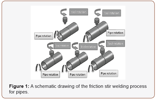
There are four key process parameters which can be differ in FSW: rotation speed, traverse speed, tilt angle, and shoulder diameter. Rotation speed (N) is in units of rotations per minute (rpm) and designates the rate at which the tool rotates. Traverse speed (F) indicates the speed at which the tool traverses the material. ν is usually specified in units of inches per minute (mm/ min) [3,4].
The essential parameters influencing the two processes are typically as follows: tool rotational speed of the tool [5,6], The tool’s travel speed in the FSW process of the plates [7] while it is referred to the rotational speed of pipes in FSWoP process [8], tool pin profile [9,10], joint thickness [11]. It was evident from all these studies that the optimum levels of these parameters for optimizing the FSW of plates are not the same for the FSWoP process under the same conditions. As an example, the FSW of plates has been studied in [12] and the FSWoP in [13] under the same range of rotational speed. The effect of rotational speed for the plate on the joint’s tensile strength is entirely different from that for the pipes [14]. The Process parameters such as tool rotation speed (N) and travel speed (F) determine the strength and efficiency of the joints generated by the FSWoP process [15]. Research has been applied out in the improvement of the FSWoP process as a distinguished solid-state join the ng process ever since its invention [16]. According to the results of this paper, Al 7075-T7351 is a quench prone alloy due to faster natural aging response and enhanced mechanical properties. The natural response to aging has been assessed through the testing of transverse tensile properties and micro-hardness. Most notably, the conditions of water cooling increased the properties of tensile by about 10 percent above normal FSW. Fu RD, et al. [17] too states that tensile strength of Underwater FSW method reached 75% of base metal and the elongation is comparably better than the normal FSW joint. Moreover, the hardness and tensile strength of Underwater FSW joint were improved compared to normal FSW joint properties. Darras B, et al. [18] studied Underwater FSW for Al AA2219-T6 to clarify the enhanced value in tensile strength compared to normal FSW joint. This study also proved that the influences of water cooling is the essential cause for the underwater FSW joint to increase the strength.
Upadhyay P, et al. [19] again, focused their research on underwater FSW of Al 2219 to moreover advance the mechanical properties of the joint with varying welding temperature history. This work is able to discover that external water-cooling action in underwater FSW developed the normal FSW joint tensile value from 324 to 341 MPa. Liu H, et al. [20] conducted experimental study to different welding conditions in Underwater FSW of 6061 aluminium alloy. The experimental outcome proved that underwater joint generates less peak temperature compared to normal FSW joint [21]. The grain sizes were predicted using boundary migration model. In addition, Transmission Electron Microscopy (TEM) was used to characterize the microstructures. Kishta EE, et al. [22] conducted experimental study to Underwater FSW of AL AA2219-T6 performed an experimental analysis for improving mechanical properties in the heat-affected area (HAZ). The experimental observations during microstructural analysis uncovered that the hardness of the HAZ can be enhanced with UFSW method due to the narrowing of precipitate free zone.
Cheng, et al. [23] explain the fuzzy control of the feed rate in the final milling process. different in the cutting parameters and nonlinearities in the processes are the drawbacks in the development of suitable mathematical models. Fuzzy logic technology offers an alternative approach and models a system as a black box with variables of input and output [24,25]. The fundamental frequencies of electromagnetic radiation emitted during the FSW welds tensile failure, generated at different process parameters, were analysed using fuzzy modelling [26]. It was estimated that the fundamental frequency of weld failures from the fuzzy model was closer to the experimental results. Dewan MW, et al. [27] found that the number of the membership functions (MF) and their locations on the universe of discourse influenced the fuzzy algorithm, compared to the shape variations of MFs. Zhang Q, et al. [28] developed a systematic datadriven fuzzy modelling approach to AA5083 Aluminum alloyrelated FSW behaviour with microstructural features, mechanical properties, and overall weld quality. The extracted models have proven to be accurate, interpretable, and resilient, and can be applied to facilitate the optimal design of process parameters to achieve the desired welding properties. Hence, the FSW process parameters, rotation speed, travels speed, and shoulder diameter, effect the tensile strength and hardness underwater FSWoP joints. There is a gap between predicting tensile strength and hardness for different parameters and for various materials. This gap could be filled by developing a fuzzy logic-based model for the underwater FSWoP process. In this work, an attempt was made to develop a straightforward fuzzy model for the prediction of weld strength and hardness, within the range of the process parameters, which could provide a perfect joint through utilize underwater FSWoP.
Materials and Method
Materials
The FSWoP process was conducted to join two pieces of Al 6061 pipes. Each pipe was 30 mm in outer diameter and 3 mm in thickness. Table 2 shows the chemical composition of the Al 1050 material of the pipes (Table 1).
Table 1:Chemical composition (Wt. %) of Al 1050.

Table 2:FSW Process parameters and levels.

Machine
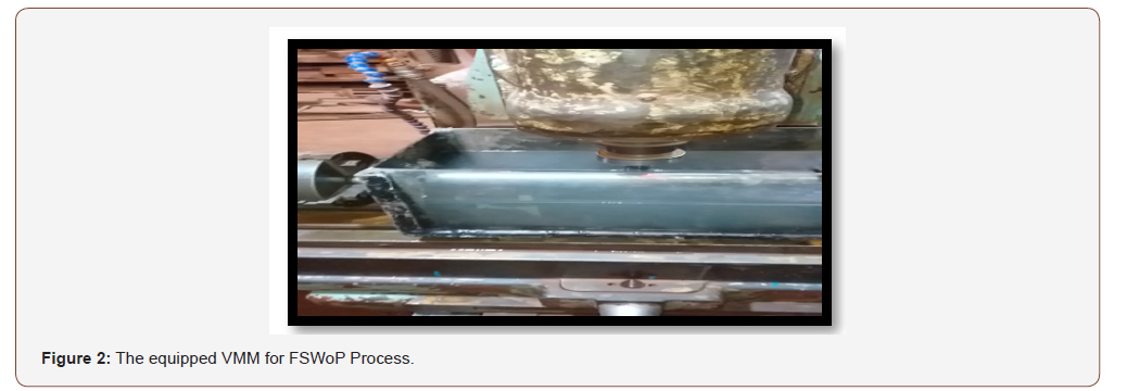
A designed and fitted vertical milling machine (VMM) for the FSWoP process was used as in Ahmed M El-Kassas, et al. [29]. Device planning usually involves a fixture layout that can handle the pipe’s spinning movement - as a parameter, it’s the travel speed (S) - to allow the device to push forward over the weld line (Figure 2).
Fixture
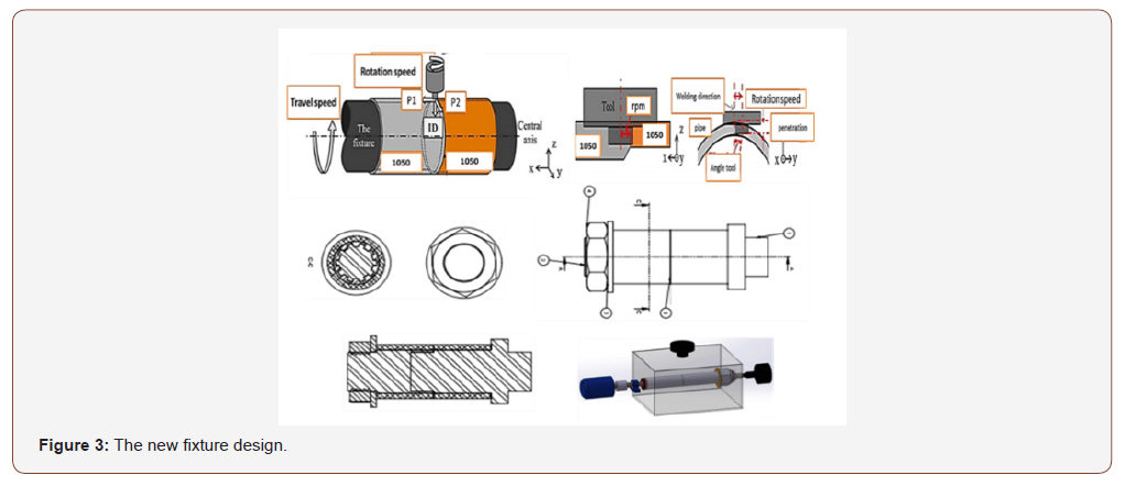
The first fixture used in the FSWoP process was composed of a solid rod back ended with a threaded part the solid rod is decomposed into two parts with the same gear teeth in this model (Figure 3). After welding and losing the nut, the rod two parts are disassembled, and every part is removed easily from inside the pipe welded.
Tool
Three unique non-consumable tools made of hard tool steel with pin diameter (D) equal to 3 mm used to weld the aluminum pipes. The pin profile is tapered with initial diameter equal to D when the final diameter is 1 mm and the pin length was 3 mm. A shoulder with an elliptical 10 × 9 mm profile and a height of 5 mm
connected the pin to the main tool body. The tool (rotated 90 degrees) that was used is shown in Figure 4.

Measurements and tests
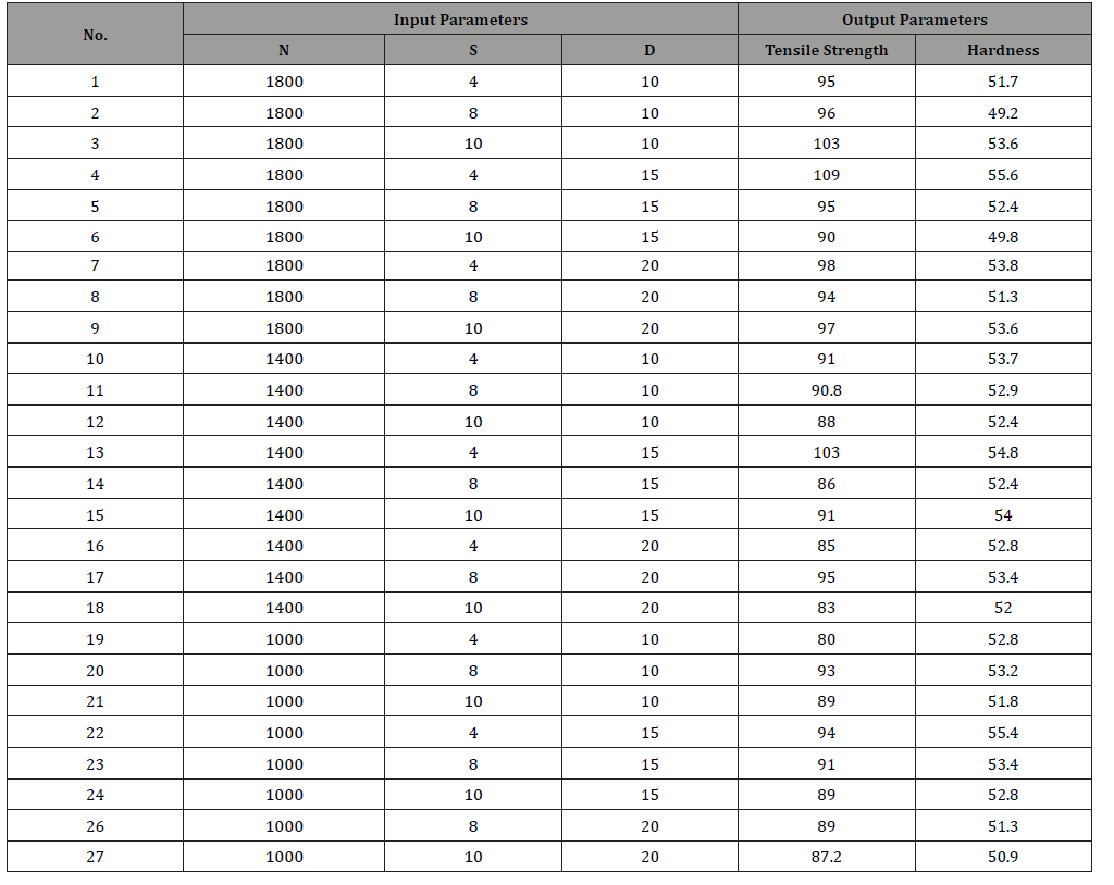
Generally, the efficiency of the welded joint is measured by its mechanical properties. The UTS was measured through the destructive tensile test while the hardness test of the Vickers was used to measure the hardness. From each welded pipe, three tensile specimens were cut, and each specimen had a configuration as shown in Figure 5. The UTS value which was reported was the average value of these three specimens. Vickers hardness number (VHN) was measured at points distributed over the weld zone and the average was calculated for each specimen. Both values of UTS and VHN for each experimental run are mentioned in Table 2.

FSW process parameters
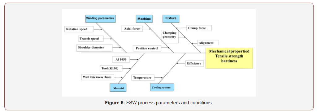
Travel speed, shoulder diameter and rotation Speed: The tool feed rate and welding speed form the main parameters of the FSW process. The feed rate affects the micro hardness of the weld and decreases as the feed rate is increased. The hardness strength of the welds has a strong dependency on the tool welding speed. The hardness strength of the weld increases first, reaches a maximum and then decreases with an increase in welding speed [30]. Figure 6 illustrates the experimental domains for the welding parameters, welding conditions and process variables.

The objective of this step is to acquire the characteristics of the UFSW process with the aid of the experimental design approach. The goal of the experimental approach is to investigate the mathematical effect of one factor independently from others, as well as the interaction between those variables on the process output. Statistical models have to be derived in spite of the variability in the experimental results. The collection of relevant experimental data mean value of the results, a qualitative estimate of the variability of the results, and techniques to access the validity of our models form a sequence of events to be followed in order to reach the correct conclusions [31]. The characteristics of the FSW process are acquired with the aid of the experimental design as illustrated in Figure 7. The regression models are implemented in MATLAB for simulation purposes.
Control system architecture for a UFSW process
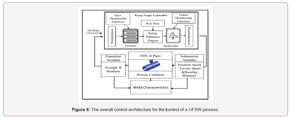
Underwater FSW is a complex process difficult to predict and model due to the characteristics of friction. In Figure 8 illustrates the proposed architecture for the control of the UFSW process. The UFSW process inputs, in the fuzzy model, can be subdivided into action variables, namely travel speed, shoulder diameter and rotation speed, and also process conditions such as the tool material and tittle angle. The system outputs are tensile strength and hardness.
Design of experiments
Design of experiments (DOE) is a systematic approach to determine the relationship between the factors affecting the process and its corresponding outcome. Taguchi method is a standardized approach in DOE to determine the best combination of inputs to plan the experiments. In the present work, experiments were conducted based on the Taguchi’s L27 orthogonal array with three levels of process parameters as shown in Table 1.
It is observed from Table 2 that a good response occurs when the input parameters are at a tool speed of 1800 rpm, a travel speed of 4mm/min, and a shoulder diameter of 15 mm. At optimum conditions, the energy input to the process leads to increased work tool interface temperatures. The generated heat in the weld zone helps to create a better stir of softened work material and increase fine material compression given by shoulder diameter and pin. However, it is identified that the rotation speed, travel speed, and should diameter be restricted to optimum values to obtain good weld tensile strength and hardness.
Fuzzy Model The schematic of the developed model is shown in the Figure 9. The fuzzy logic model consists of inputs, fuzzification module, inference mechanism, defuzzification module and output. The UFSW process parameters rotation speed, travel speed and shoulder diameter were inputs to the fuzzification module and tensile strength, and hardness is the output from the defuzzification module. Gaussian membership function was used to assign a membership value to the element, which has high efficiency in assigning the membership value to the element [32] (Table 3).
Table 3:Experimental matrix (L27) and output responses ( tensile strength and hardness).

Development of fuzzy logic model based on UFSW process parameters
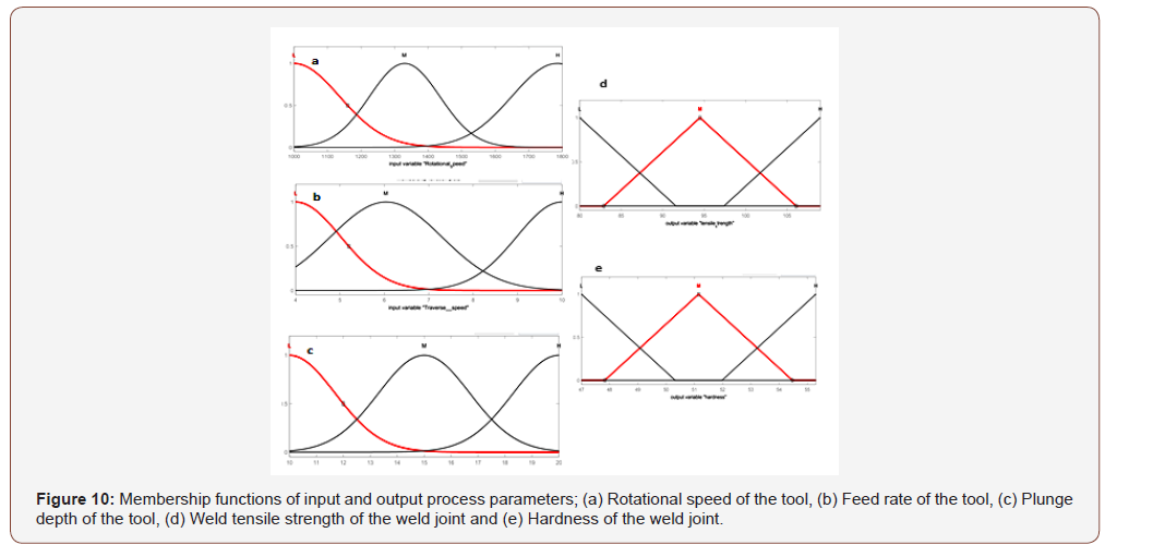
In the present work, a fuzzy logic model, based on the Mamdani method, was developed for assessing the weld tensile strength and hardness of UFSW components as the output parameters, and tool rotational speed, feed rate, and plunge depth as the input parameters. The fuzzy linguistic variables and characteristics for input and output parameters are shown in Table 1. Each input variable had 3 membership functions, which were Low, Medium, and High. The output variables also had 3 membership functions, Low, Medium, and High. MATLAB 8.0 software was used to develop and simulate the fuzzy model.
Membership functions
The choices of membership functions (MF) for fuzzification were dependent on the relevant event. The shape of the MF was a depiction of uncertainty in the fuzzy variable. Experiments were conducted for 3 levels of process parameters based on DOE to obtain good weldment. In this model, each input and output parameter have 3 levels and corresponding membership functions. The Gaussian membership function was used to describe the fuzzy sets for input variables, in order to enhance them and address the complex interactions of input parameters. Triangular membership function generally possesses gradually increasing and decreasing characteristics with one distinct value. Therefore, the output variables are inferred by triangular membership functions. Fuzzy membership functions for the input are shown in Figures 10(a) - 5(c) and the corresponding output variables are shown in Figures 10(d) and 10(e). The parameters for the Gaussian and triangular membership functions were altered by post-tuning the fuzzy model viewer for higher prediction accuracy using MATLAB software.
Fuzzy rule
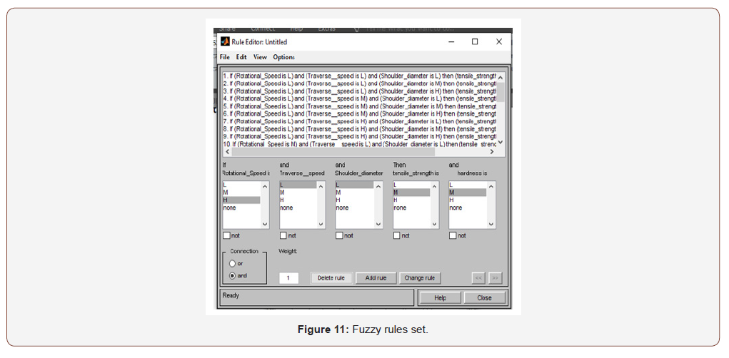
A fuzzy inference engine performs inference operations on activated fuzzy rules at each computational cycle to constitute an aggregate output. The fuzzy rules are formed with fuzzy inputs, which could be obtained from experts, experiments, and past data of the process. Experimental data were used to develop the rules for a Mamdani type fuzzy inference system with 3 inputs and 2 outputs. A rule base with a set of 27 rules was formulated, based on the input process parameters for predicting the weld tensile strength and hardness of weld joints as the output, as shown in Figure 11. The ranges of process parameters were narrow in this UFSW process. Hence, all input parameter combinations were used to obtain consistent outputs.
Defuzzification
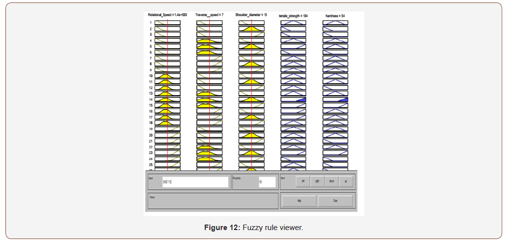
In this fuzzy logic model, a centroid of area (COA) defuzzification scheme is engaged, due to its extensive acceptance and capability in giving accurate results, rather than other defuzzification methods. The overall fuzzy output of the Mamdani fuzzy model results from adopting the AND logic operation into the triggered
rules, and the rule viewer is shown in Figure 12.
Results
Effect of process parameters
The weld tensile strength and nugget hardness of UFSW aluminium components were simulated from the developed fuzzy model. The experimental data set was used to investigate fuzzy model accuracy and error. The individual error percentage was calculated using the Eq. (1);
Individual Error (%) = (Experimental-Fuzzy predicted)/ Experimental
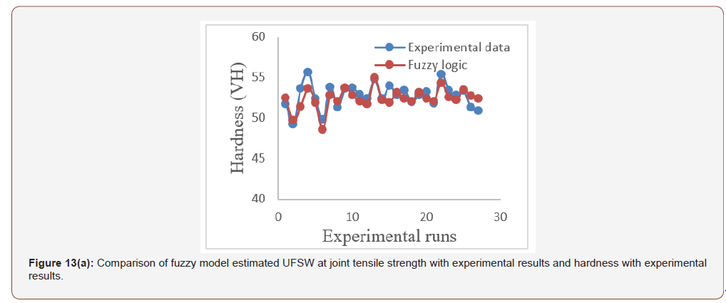
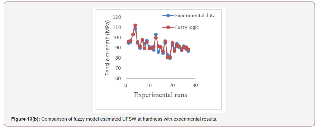
Figures 13(a) and 8(b) shows the comparison between the fuzzy model estimated values of output parameters with that of the experimental results. The absolute error percentage between the experimental and fuzzy logic model predicted values of output parameters were computed by averaging the individual error percentage. The fuzzy logic model estimated results demonstrated a close agreement with the experimental data, with an absolute error of 1.92 % for weld tensile strength and 2.052 % for hardness, respectively. Hence, the developed fuzzy logic model could be used to predict the joint tensile strength and hardness within the specified range of input parameters considered.
Surface plots for effect of process parameters
The fuzzy model was simulated for different values of input process parameters and the weld tensile strength of UFSW joint was predicted, as shown in Figures 14(a) - 14(c). As can be seen in Figure 14(a), there is significant increase in the tensile strength of the UFSW joint with increases in tool rotational speed and decreases travel speed.
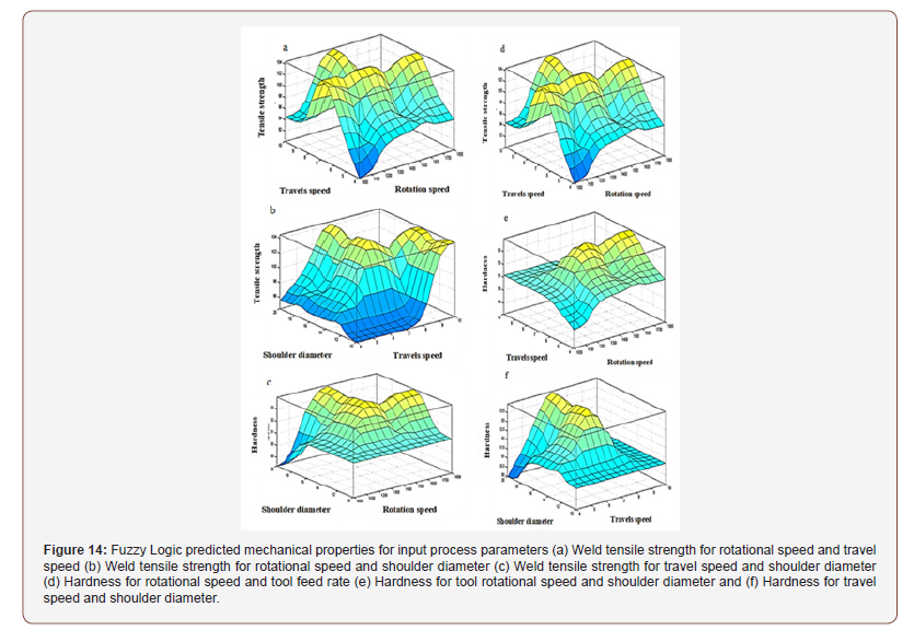
However, the weld tensile strength and hardness reached a most favourable value in the speed range of 1000 to 1400 rpm and with a 4 to 10 mm/min travel speed. It is clearly seen that both the tool rotational speed and the travel speed are very significant in changing the weld tensile strength and hardness.
The higher values of input parameters provide the lower tensile strength of the UFSW joint.
It is observed from Figure 14(b) that there is an increase in the tensile strength of the UFSW joint with increases in tool rotational speed and shoulder diameter. However, the tensile strength and hardness reached a favourable value in the speed range of 1000 to 1400 rpm and at a 10 to 14 mm shoulder diameter. It is clearly seen that high rotational speed and shoulder diameter provides lower tensile strength of the FSW joint.
As can be seen in Figure 14(c), there is significant increase in the tensile strength of the FSW joint with increases in travel speed and shoulder diameter.
The lower values of shoulder diameter and travel speed provide the lower tensile strength of the FSW joint.
A plunge depth of 16 mm and a feed rate above 8 mm/min provides a considerable value of tensile strength. Figures 14(d) - 14(f) are surface graphs showing the relationship between input parameters and the fuzzy logic model predicted nugget hardness of the UFSW joint. The tool rotational speed, travel speed, and shoulder diameter influence the change in hardness.
As can be observed from Figure 14(a), there is a significant increase in the hardness of the UFSW joint with an increase in tool travel speed.
However, it reaches a most favourable value in the speed range of 1200 to1400 rpm and with a 4 to 8 mm/min travel speed. The higher values of tool rotational speed and travel speed provide the lower hardness of the FSW joint. Figure 14(b) shows that there is an increase in the hardness of the UFSW joint with an increase in tool rotational speed and in shoulder diameter.
However, the hardness reaches a favourable value in the range of tool rotational speed between 1200 and 1400 rpm and at a shoulder diameter between 10 and 14 mm. It is observed from Figure 14(c) that there is a considerable value of the hardness of the UFSW joint with a plunge depth above 10 mm, and a travel speed between 8 and 10 mm/min. It is obvious that the intense shoulder diameter provides lower hardness in the UFSW joint.
Conclusion
The proposed systematic method of fuzzy logic determined adequately optimal process parameters for UFS welded Al 1050 pipes. The results of the present investigation can be summarized below,
It was found that the input process parameters of tool rotational speed, traverse feed rate, and shoulder diameter notably influence both the weld tensile strength and hardness of UFSW joints.
The developed fuzzy logic model performs well in monitoring the weld tensile strength and hardness of underwater friction stir welded Al 1050 pipes.
The experimental and simulation analysis confirmed a good agreement between the fuzzy model and the experimental results, with the accuracy of 98.08 and 97.948 % for the weld tensile strength and hardness of underwater FSW joints, respectively.
The presented fuzzy logic scheme could be utilized as a control algorithm for the online monitoring and control of underwater FSW processes within a significant range of process parameters, in order to obtain good weldment.
Acknowledgement
We would like to acknowledge the fund provided by the Modern Academy for Engineering and Technology, through the grant -Research center.
Conflict of Interest
Conflict of interest On behalf of all authors, the corresponding author states that there is no conflict of interest.
References
- Wayne M Thomas, Edward D Nicholas, James Needham, Saffron Walden, Michael G Murch, et al. (1991) US Patent No. 5460317.
- RS Mishra, ZY Ma (2005) Friction Stir Welding and Processing. Materials Science and Engineering 50(1-2): 1-78.
- PL Threadgill (2007) Terminology in Friction Stir Welding. Science and Technology of Welding & Joining 12(4): 357-360.
- Ahmed M El-Kassas, Ibrahim Sabry (2019) Using Multi Criteria Decision Making in Optimizing the Friction Stir Welding Process of Pipes: A Tool Pin Diameter. International Journal of Applied Engineering Research 14(18): 3668-3677.
- K Aruna Prabha, Prasad Kumar Putha, Balla Srinivasa Prasad (2018) Effect of Tool Rotational Speed on Mechanical Properties of Aluminium Alloy 5083 Weldments in Friction Stir Welding. Materials Today: Proceedings 5(9): 18535-18543.
- DG Hattingh, LG von Welligh, D. Bernard, L Susmel, R Tovo (2016) Friction Stir Welding of 38 mm OD 6082-T6 Aluminium Tubes. Journal of Materials Processing Technology 238: 255-266.
- Subramanya Prabhu, Arun Kumar Shettigar, Karthik Rao, Shrikantha Rao, Mervin Herbert (2017) Influence of welding process parameters on microstructure and mechanical properties of friction stir welded aluminium matrix composite. In Materials Science Forum 880: 50-53.
- AM Khourshid, I Sabry (2013) Friction Stir welding Study of Aluminum Pipe. International Journal of Mechanical Engineer 2(3): 331-339.
- Vahid Moosabeiki, Ghasem Azimiroeen, Mostafa Ghayoor (2012) Influences of Tool Pin Profile and Tool Shoulder Curvature on The Formation of Friction Stir Welding Zone in AA6061 Aluminium Alloy. Advanced Materials Research 445: 789-794.
- Ibraheem Sabry, Ahmed M. El-Kassas (2018) Comparative Study on Different Tool Geometrics in Friction Stirred Aluminum Welds Using Response Surface Methodology. 4th International Conference on Welding and Failure Analysis of Engineering Materials (WAFA), Aswan, Egypt.
- AM Khourshid, Ahmed M El-Kassas, HM Hindawy, Ibraheem Sabry (2016) Optimization of Friction Stir Welding Parameters for Joining Aluminum Pipes Using Regression Analysis. International Journal of Civil Mechanical and Energy Science 2(1): 1-5.
- AL Murshdy, Naji Chabuk QK (2016) Effect of Tool Shape Geometry and Rotation Speed in Friction Stir Welding of 2024-T3. The Iraqi Journal for Mechanical and Material Engineering 16(3): 176-185.
- AM Khourshid, Ahmed M El-Kassas, Ibraheem Sabry (2015) Integration between artificial neural network and responses surfaces methodology for modelling of friction stir welding. International Journal of Advanced Engineering Research and Science 2(3): 67-73.
- Ahmed M El-Kassas, Ibrahim Sabry (2019) Using Multi Criteria Decision Making in Optimizing the Friction Stir Welding Process of Pipes: A Tool Pin Diameter. International Journal of Applied Engineering Research 14(18).
- Ibrahim Sabry, Ahmed M El-Kassas, AM Khourshid (2017) Comparison of RSM and RA with ANN in Predicting Mechanical Properties of Friction Stir Welded Aluminum Alloy Pipes. Engineering and Technology in India 8(1): 1-14.
- S Sree Sabari, S Malarvizhi, V Balasubramanian, G Madusudhan Reddy (2016) Experimental and numerical investigation on under-water friction stir welding of armour grade AA2519-T87 aluminium alloy. Defence Technology 12(4): 324-333.
- Rui-dong Fu, Zeng-qiang Sun, Rui-cheng Sun, Ying Li, Hui-Jie, et al. (2017) Improvement of weld temperature distribution and mechanical properties of 7050 aluminum alloy butt joints by submerged friction stir welding. Material & Design 32(10): 4825-4831.
- Basil Darras, Emad Kishta (2018) Submerged friction stir processing of AZ31 magnesium alloy. Materials & Design 47: 133-137.
- Upadhyay P, Reynolds AP (2019) Effects of thermal boundary conditions in friction stir welded AA7050-T7 sheets. Materials Science and Engineering: A 527(6): 1537-1543.
- HJ Liu, HJ Zhang, L Yu (2011) Effect of welding speed on microstructures and mechanical properties of underwater friction stir welded 2219 aluminum alloy. Materials & Design 32(3): 1548-1553.
- HJ Zhang, HJ Liu, L Yu (2011). Microstructure and mechanical properties as a function of rotation speed in underwater friction stir welded aluminum alloy joints. Material & Design 32(8-9): 4402-440.
- Emad Eldin Kishta, Basil Darras (2014) Experimental investigation of underwater friction-stir welding of 5083 marine-grade aluminum alloy. Proceedings of IMechE Part B: Journal of Engineering Manufacture 230(3): 458-465.
- YS Tarng, ST Cheng (1993) Fuzzy control of feed rate in end milling operations. International Journal of Machine Tools and Manufacture 33(4): 643-650.
- Rodolfo Elias Haber, Clodeinir R Peres, Angel Alique, Salvador Ros, Carlos Gonzalez, et al. (1998) Toward intelligent machining: Hierarchical fuzzy control for the end milling process. IEEE Transactions on Control Systems Technology 6(2): 188-199.
- B Parida, S Pal (2015) Fuzzy assisted grey Taguchi approach for optimization of multiple weld quality properties in friction stir welding process. Science and Technology of Welding & Joining 20(1): 35-41.
- EH Mamdani, S Assilian (1975) An experiment in linguistic synthesis with a fuzzy logic controller. International Journal of Man-Machine Studies,7(1): 1-13.
- Mohammad W Dewan, Daniel J Huggett, T Warren Liaoa, Muhammad A Wahab, Ayman M Okeil (2016) Prediction of tensile strength of friction stir weld joints with adaptive neuro-fuzzy inference system (ANFIS) and neural network. Materials & Design 92: 288-299.
- Qian Zhang, Mahdi Mahfouf, George Panoutsos, Kathryn Beamish, Ian Norris (2011) Multiple Characterization Modelling of Friction Stir Welding Using a Genetic Multi-objective Data-driven Fuzzy Modelling Approach. IEEE International Conference on Fuzzy Systems, pp. 2288-2295, Taiwan.
- AM Khourshid, I Sabry (2013) Analysis and design of Friction stir welding. International Journal of Mechanical Engineering & Robotics Research 2(3): 233-241.
- Ahmed M El-Kassas, Ibrahim Sabry, Abdel-Hamid Ismail Mourad, Dinu Thomas (2019) Characteristics of Potential Sources - Vertical Force, Torque and Current on Penetration depth for Quality Assessment in Friction Stir Welding of AA 6061 Pipes. International Review of Aerospace Engineering 12(4): 195.
- Tyler A Davis, Phuong D Ngo, Yung C Shin (2012) Multi-level fuzzy control of friction stir welding power. The International Journal of Advanced Manufacturing Technology 59(5-8): 559-567.
- John Yen, Reza Langari, Lofti A Zadeh (1995) Industrial Applications of Fuzzy Logic and Intelligent Systems. IEEE press.
-
Ibrahim Sabry, Nabil Gadallah, M Abdel Ghafaar, MM Abdel-Mottaleb . Optimization of Process Parameters to Maximize Ultimate Tensile Strength and Hardness of Underwater Friction Stir Welded Aluminium Alloys using Fuzzy Logic. Mod Concept Material Sci. 3(1): 2020. MCMS. MS.ID.000551.
-
Friction stir welding, fuzzy logic, tensile strength, hardness test, Material, Aluminium alloy, FSW joint, Tool, Process parameters, Diameter, Rotational speed
-

This work is licensed under a Creative Commons Attribution-NonCommercial 4.0 International License.


