 Mini Review
Modeling of Partially Cemented Soils in the Las Vegas Valley
Sherif Elfass1*, Evan Saint Pierre2, Robert Watters3 and Gary Norris4
1Research Associate Professor, University of Nevada Reno
2Staff Engineer, Shannon and Wilson Geotechnical and Environmental Consultants
3Professor, University of Nevada Reno
4Emeritus Professor, University of Nevada Reno
Sherif Elfass, Research Associate Professor, University of Nevada Reno, USA.
Received Date: July 26, 2019; Published Date: July 29, 2019
Abstract
Cemented soils deposits located in Las Vegas valley have long been a challenge for engineers. These deposits can distribute considerable loads over a large area. They are, however, difficult to model or to predict their behavior. For engineering purposes, these cemented soils, also commonly referred to as Caliche, are difficult to characterize: their thickness, lateral extent and strength. This erratic and heterogeneous nature can result in inconsistent design and performance of foundations. Fifty-three cored specimens from block samples of partially cemented soils (aka Caliche), collected from the Las Vegas valley, were tested for their unconfined compressive strength (UCS). Laboratory shear and pressure wave velocities were measured for all samples and relationships between lab shear wave velocities, material unit weight and unconfined compressive strength were generated. This article discusses a material model for the partially cemented soils using results obtained from these UCS tests. The model, which uses parameters from shear wave velocity correlations, generates the stress-strain relationship of cemented soils and distinguishes three cementation levels.
Sample Collection and Preparation
Since in situ coring was out of the scope of the project, obtaining block samples from shallow excavations was identified as a viable alternative. Several construction projects in Las Vegas were identified and communication with the contractors was established. After evaluating several options, a site was selected, and sample collection was coordinated with the contractor.
Details of the location and field collection of block samples, their transport to the Rock Preparation Lab of the Mining Engineering Department at the University of Nevada Reno, the coring of samples and further preparation of the 53 specimens to be tested are presented by Saint-Pierre [1].
Unconfined Compressive Strength Tests
Unconfined Compressive Strength (UCS) teste were performed using a Tinius Olsen displacement controlled, hydraulically powered load frame. The equipment uses manual controls with digital output. Compressive strength testing was conducted in accordance with ASTM D7012. The strain rate was maintained as constant as possible and failure of test specimens never occurred before two [2] minutes nor after 15 minutes.

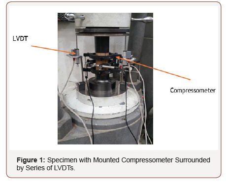
Vertical sample deformation, used to assess axial strain, was captured using different sensors (Linear Variable Differential Transformer (LVDT), compressometer, strain gauge and laser). The compressometer, which is used in tests of concrete samples, is not a piece of equipment that is typically used in the testing of rock samples. Its records deformation in the central portion of the sample, away from the sample ends, thus reducing end effects. After extensive comparisons, data from LVDTs was used to generate the material model. For every test, three LVDTs were placed at 120 degrees around the specimen as shown in Figure 1.
A steel blank was placed above and below the specimen to ensure the platens did not contact the axial and lateral displacement sensors of the compressometer. Once the hydraulics were engaged, the bottom plate advanced upwards. Specimens were loaded beyond failure to better establish and understand the failure mechanism.
Material Model of Cemented Soil
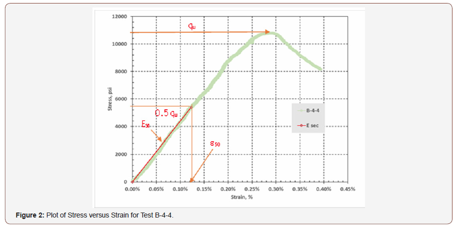
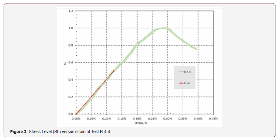
A stress-strain plot for every specimen tested was obtained and adjusted for seating and crack closure, which is not the focus of this article. Figure 2 presents a stress-strain plot for one of the samples tested (B-4-4). The y-axis of each curve was modified to show stress level (SL) instead of stress. Values of the axial stress at a given point (σd) divided by the peak stress (qu) yield the stress level (SL) values, i.e. SL = σd/qu. Figure 3 is the corresponding plot of SL versus strain. It is relative to this SL vs. strain curve that a model (an equation) is sought. This process made the calibration more achievable (Figures 3).


Since cemented soils behave like rock under axial load, the stress-strain behavior was expected to be linear up to stress level of 50% (Hudson 2000). Thus, a secant slope (Esec) from the adjusted origin to the stress at 50% of the strength (UCS) was established for all test curves. Such Esec values are the elastic modulus (or E50) values from Figure 2. The stress-strain relationship for SL ≤ 0.5 is presented in Equation 1.

Where ε is the strain and E50 is the Young’s Modulus up to SL = 50% qu and E50 can be obtained from shear wave velocity correlations (not subject of this article). Response from stress level of 50% to 100% was modeled using the following equation:

Where ε50 is the strain at the stress level of 50% and is equal to qu/(2*E50), and λ is a calibration factor? To establish the variation in λ for SL > 0.5 for cemented soils, Equation 2 was rearranged to give Equation 3

Test data from UCS tests on the 53 samples was used to back calculate the values of λ as function of SL. The best fit is presented in Equation 4.

Conclusion
A new model for partially cemented soils was presented. The model uses parameters that can be obtained from relationships already developed as part of a larger study. The model along with the derived relationships can be used to assess the performance of foundations embedded in partially cemented soils.
Acknowledgements
The effort presented herein was part of a project sponsored by the Nevada Department of Transportation (NDOT).
Conflict of Interest
No conflict of interest.
-
Sherif Elfass, Evan Saint Pierre, Robert Watters, Gary Norris. Modeling of Partially Cemented Soils in the Las Vegas Valley. Mod Concept Material Sci. 1(4): 2019. MCMS.MS.ID.000519.
-
Cemented soils, UCS, Stress-strain, LVDT, Vegas Valley, Material
-

This work is licensed under a Creative Commons Attribution-NonCommercial 4.0 International License.


