 Research Article
Influence Factors of Frequency Response Characteristics for a Novel Velvet Frequency Selective Fabric
Yajing Wang1,2, Hong Xiao2*, Huanhuan Cheng3 and Meiwu Shi2
1Beijing Jike Protection & Tech.Co., Ltd, China
2Institute of Quartermaster Engineering & Technology, China
3College of Textiles, China
Xiao Hong, Institute of Quartermaster Engineering & Technology, Institute of System Engineering, Academy of Military Science, PLA, Beijing, China.
Received Date: July 23, 2018; Published Date: August 16, 2018
Abstract
In this paper, a novel three-dimension (3D) frequency selective fabric (FSF) based on U-shaped velvet, using metallic yarns as the conductive unit material via cluster velvet weaving method, is prepared. U-shaped unit structure is formed by two ending points of the dipole unit extending into the space Z-direction. By testing and analyzing transmission coefficient of specimens, frequency response characteristics are studied. Compared to FSF with dipole unit structure, the new velvet fabrics with the same unit length have double-frequency resonance at 2 -18GHz. With an increase of inclination angle of velvet, the resonance frequency is changed slightly, accompanied by a trend of decreasing first and then stabilizing. The density of conductive yarns is enlarged, and the resonance frequency moves slowly to higher frequency. If the total length of U-shaped unit on the bottom is greater, the resonance frequency will go to lower frequency. The number of connected U type rarely affects the resonance frequency with the same bottom length. And this work shows that U-shaped velvet FSFs can be designed with more parameters comparing with planar FSF. What’s more, they also have a multi-frequency response character.
Keywords: U-shaped velvet fabric; Frequency selective surface; Influence factors; Frequency response characteristics
Introduction
Frequency selective surface (FSS) is a periodic structure with one-dimensional or two-dimension (2D) array. The traditional FSS unit structure is a metal patch or metal aperture. With metal patch structure, FSSs would reflect the electromagnetic wave in the vicinity of the resonance frequency. The metal aperture-type FSSs transmit the electromagnetic wave around the resonance frequency [1]. In recent year, the FSSs have been investigated by many researchers about the structure of single-layer [2,3], multi-layer [4- 7], or 3D [8-10], metal unit. Changing the design of electromagnetic materials, unit size, arrangement and other parameters, metal FSSs can obtain the specific resonance frequency, such as broadband, multi frequency, better angle stability, miniaturization or other characteristics.
Combined with the FSS, the conductive fiber is used as the structural material, and the flexible FSF with electromagnetic function is manufactured by means of textile processing. This research not only has an important scientific significance, but also has a practical value in the field of radar absorbing material, communication window, fabric antenna, flexible functional clothing and so on [11,12]. At present, domestic and foreign researchers have studied 2D FSF by screen printing [13,14], weaving [15], weft knitting [16,17], embroidery [18,19], selective chemical plating [20], ink-jet printing [21,22], or another textile processing.
In this paper, we propose a novel FSF with 3D U-shaped velvet structure. Compared with the planar FSS, the U-shaped velvet FSF has a 3D design, which increases design parameters. The velvet FSF would have a more flexible lightweight characteristics and more structure patterns, which a conventional FSS does not have [22,23].
As members of our research group, Xiao et al. [24]. proposed the U-shaped velvet FSS textiles, which are made by the technology of tufted carpet weaving. The parameter design of electromagnetic functional fabric can be divided into four parts, including the yarn material, the unit shape, the grid array and the electromagnetic wave incidence condition. In the unit design part, Cheng et al. [22] have already explored the influence of the velvet height, the unit cell size, the bottom connectivity on frequency response characteristics. In this paper, the influence factors of other unit design, such as planar and 3D shape, the linear density of the conductive yarn, the inclination angle of velvet and different U-shaped connective conditions, are continued to be studied.
Experiment
Specimen preparation
Specimens were made by handmade or velvet weaving method. First, samples were manufactured by hand in the preliminary. Second, experimental samples were produced by a tufted carpet sample loom, where U-shaped connective condition was related to the cell structure of tufting carpet. It is worth noting that the conductivity of other experimental materials is negligible except conductive yarns.
FSF specimens with the cell structure of planar dipole and 3D U shape
U-shaped structure unit, made by conductive yarns, is derived by two ending points of the dipole unit extending along the space Z-direction. And it is a kind of 3D structure. Taking into account the sample preparation process of dipole element and U-shaped element, samples need cut some conductive yarns to form design patterns (represented by red lines in Figure 1 & Figure 2). In the actual production process, FSFs of the U-shaped structure can be woven by the tufted carpet loom.
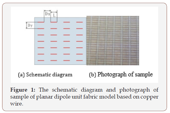
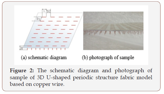
2D dipole and 3D U-shaped FSF samples were manufactured by using 2 strands of copper wire (the diameter of single strand is 0.1 mm) as structure unit, shown in Figure 1 & Figure 2 respectively. And sample substrate was common cardboards. Of course, nonconductive fabric also can be used as substrate. Experiments of different unit length of dipole and U type periodic structure model were prepared to explore the frequency response difference. The specific parameters of FSF specimens are listed in Table 1.
Table 1: Sample parameters based on the model of copper wire.

U-shaped velvet FSF specimens with different assembling number of silver filaments in the unit cell structure
For independent U-shaped FSFs, a research on the assembling number of silver filaments has been carried out. The assembling number difference of yarns shows the linear density variation of conductive yarns. Meanwhile, it determines the amount of conductive yarns in the actual weaving. And the conductive yarn linear density is a significant parameter in FSF weaving process.
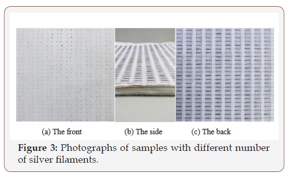
Silver filaments, the single yarn fineness of 10 tex, were used to build up U type FSF. The FSF specimens have the same unit size and different assembling number of silver filaments, including 4, 10, 16, 22 and 28 yarns, as shown in Table 2. The substrate is polyester fabric and cellular PE plates, supporting conductive yarns to prevent collapsing. The manual samples are shown in Figure 3.
U-shaped velvet FSF specimens with different inclination angles of velvet
Velvet inclination is a very common phenomenon for velvet fabrics. Therefore, the velvet inclination plays an important role in this design. In the process of samples preparation, we need take 1 or 2 layers cellular PE plates (1mm thick per layer) of sample Ag-S3-# in Table 2, and then pull cellular PE plates along the extension direction of length L from the outside to the inside in turn. The purpose is to make velvet incline to certain angle θ (see Figure 4a). Finally, FSF specimens with inclination velvet were prepared.
Table 2: Sample parameters based on different number of silver filaments.

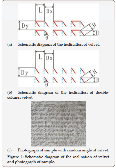
Random inclination angles of velvet refer to different inclination angles θ and different inclination direction. Samples need to be carried out the following processing, taking down all the cellular PE plates, achieving random inclination angles by hand and manufacturing specimens with random inclination angles, as shown in Figure 4c. Empirical prediction is that uniform changes in the velvet inclination directions and angles cause frequency response regularity, and that the U-shaped velvet FSF with random angles generates connectivity between velvets in the result of electromagnetic wave reflection. Velvet inclination is closely related to the shape of the carpet, which is of great value.
U-shaped velvet FSF specimens with different connectivity conditions
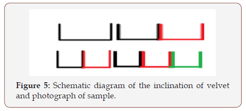
The unit structure of the above experimental samples is independent U type. However, there are a great many different shapes in practice, such as the cube, cylinder and so on. Therefore, it is very necessary to study different connection modes of U-shaped unit structures, as shown in Figures 5 & 6. Figure 5 indicates that the total length of the unit cell at the bottom is the same, and that the number of U type is different. Another kind of connectivity is continuous unit cells with the same length of single U type and different U type number, as seen in Figure 6.
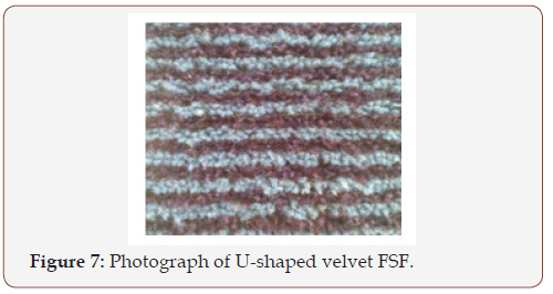
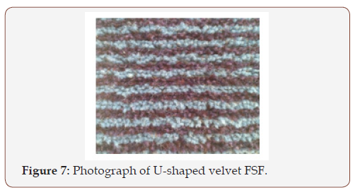
By adjusting needle distance, velvet higher and other parameters of the machine, U-shaped velvet FSF specimens with different connectivity conditions were produced by the tufted carpet sample loom. Unit cell structures were formed by Silver filaments. Common polyester yarns had a supporting role and substrates were ordinary carpet substrate cloth. U-shaped Velvet FSFs are shown in Figure 7. The specific parameters are shown in Table 3.
Table 3: Sample parameters based on different U-shaped connectivity conditions.

Experimental test
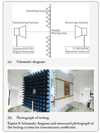
In this work, the shielding chamber was used to test the transmission coefficient of samples. Testing system included an Agilent E8257D signal generator (250KHz-40GHz), an E7405AEMC spectrum analyzer (100Hz-26.5GHz), two horn antennas (1GHz- 18GHz) and an absorbing screen etc. According to GJB 6190-2008 《Measuring method for shielding effectiveness of electromagnetic shielding materials》, environmental conditions, transmitting and receiving antenna position were set up. The sample transmission coefficient of 1-18GHz was tested by transverse electric wave. Figure 8 is schematic diagram and measured photograph of the testing system, where the center of the transmitting antenna, the testing samples and the receiving antenna were located on the same horizontal line. And the testing sample size was 18cm×18cm.
Results and Analysis
Comparison of frequency response characteristics of the 3D U-shaped velvet FSF and planar dipole cell structure FSF
The Cu-L series samples, with different unit length of 6mm, 9mm and 12mm, were the planar dipole FSF and the velvet high H of samples was 0mm. As contrast, the velvet high of the Cu-U series samples was 6mm and they had the same unit length of 6mm, 9mm and 12mm. In addition, the other parameters were the same. The test results are shown in Figure 9.
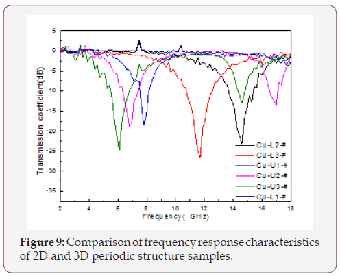
When the incident wave is perpendicular to samples, electrons in the direction of electric field (generated by the decomposition of electromagnetic waves) produce oscillation. Part of the energy is transmitted through the sample, and the rest is absorbed by electrons. At a certain frequency, all transmission energy of electromagnetic wave is changed to electrons. In other word, the additional scattering is produced by electrons can offset the electromagnetic wave scattering field. The resonance phenomenon will occur. This frequency point is called resonance frequency [25].
As it can be seen in Figure 9, the transmission coefficient of specimens at 2-18GH were tested. The element structure of 2D FSF is the planar dipole and 3D FSF structure is U type. With the same bottom unit length L of 6mm, 2D FSF(Cu-L1-#) does not produce a resonance in the 2-18GHz band, while, an independent U type periodic structure 3D FSF(Cu-U1-#) generates a resonance at 8GHz. When unit length L is 12mm, the resonance frequency of 2D FSF(Cu-L2-#) is 14.6GHz and 3D FSF(Cu-U2-#) has two resonance points, which are 6.8GHz and 17GHz. 2D FSF(Cu-L3-#) with the element length of 18mm resonates at 11.7GHz and 3D FSF(Cu-U3-#) resonates at 6.1GHz and 14.6GHz. These can be concluded as follows: (1) the 3D U-shaped velvet FSF, which is extended from the direction of the dipole height, has a dual band effect. (2) when the resonance points are the same (e.g.14.6GHz), samples may be composed of different unit cell structures. (3)the resonance point of 2D FSF, whose parameters are the same as the 3D except the high H (e.g. H=0mm and H=6mm), is between the two resonance points of the 3D FSF and slightly closer to the larger resonance point of the 3D FSF.
The influence of the velvet assembling number
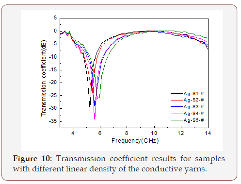
The linear density of yarns is an important design parameter of FSF. In this paper, the velvet linear density is represented by the assembling number of silver filament. The assembling number of conductive yarns in the unit structure of the sample Ag-S series was 4, 10, 16, 22 and 28 respectively, and corresponding yarn linear density was 408dtex, 1019dtex, 1630dtex, 2241dtex and 2852dtex. In addition to the assembling number of conductive yarns, the other data of the specimens were the same. Test results of transmission coefficient are shown in Figure 10. The resonance frequency of the samples varies from 5.25 GHz to 5.83 GHz. With an increase of the conductive yarn linear density, the distance between the units and the unit coupling capacitance decrease. As a result, the resonance frequency is increased slowly. Because of increasing velvet linear density, the gap between velvet may affect the frequency response characteristics.
The influence of the inclination angle of velvet
Qualitative study of velvet inclination is investigated, namely this is to explore the impact of different inclination angle on transmission coefficient. In the experiment, the sample Ag-S3-# was prepared with silver filaments of 16 assembling number. The inclination angle θ of velvet is shown in Figure 4a. The doublecolumn model is obtained by cutting the dipole of U type, as shown in Figure 4b. Arbitrary angle is presented by velvet inclination to different directions, as shown in Figure 4c. Experimental results are shown in Figure 11.
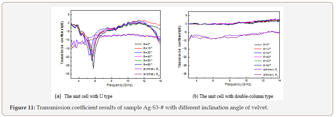
In Figure 11a, the sample has a U type unit and the resonance frequency is in the range 5.25 - 5.76GHz. In Figure 11b, the transmission coefficient of the sample with a double-column type unit is about 0dB. The transmission loss of U-shaped element samples with arbitrary angle is about -8dB, which is near the transmission loss of double-column element, around -7dB. The analysis is as follows.
Inclination angle θ: Chen et al. analyzed that the resonance point moved to the lower frequency with an increase of the velvet height or the unit length L [22]. However, the increase of inclination angle θ leads to two results, the equivalent height of the unit decreasing and the velvet equivalent length in the electric field increasing. When θ is less than a certain angle, the impact of the equivalent height on the resonance frequency is less than the impact of the velvet equivalent length. Thus, resonance frequency moves to the low frequency. When θ is greater than a certain angle, the resonance frequency maintains a certain value. As a whole, the resonance frequency has decreased gradually and then held the resonance frequency nearby a constant value during the inclination angle θ increasing.
Double-column structure: The transmission coefficients of double-column structure unit samples with different angles remain unchanged, indicating that the influencing factor of the resonance frequency is mainly the U-shaped structure at the bottom, instead of a separate double-column structure.
Arbitrary angle: Velvet with arbitrary angle inclination contributes to the electric connectivity between velvet, which results the sample to form conductive metal plate, reflecting electromagnetic wave. As Θ is the arbitrary angle, the transmission coefficient of the U-shaped FSF is near to that of the double-column type structure unit.
The U-shaped FSS is commonly applied to velvet carpet products. Ordinary non-conductive yarns space apart the conductive fiber to support and fix the unit cell structure. And compact velvet arrangement can effectively solve the problem of velvet inclination.
The influence of U-shaped connective conditions on the bottom
The same total length L of the unit cell, the different number of U type: Generally, a U type, woven by the tufted carpet loom, is far less than 9mm. Hence, we need explore the impact of the number of U type under the condition of the same total length L of the unit cell, which determines whether samples of different cell shapes are manufactured by the tufted carpet sample loom or not.
When the unit total length L of the bottom was 12mm, the sample of single-U type Ag-U-1# and the sample of double-U type Ag-2U-# were produced respectively, as seen in Figure 5. And testing results for the transmission coefficient are shown in Figure 12 a. When the total length L of the bottom was 18mm, the sample Ag-U-2# of double-U type and Ag-3U-# of three-U type were made. Testing results are shown in Figure 12b. In the 10-12GHz band, the resonance point of the single-U type sample with the bottom length L of 12mm is 11.8GHz. The resonance point of the double-U type sample with the same parameters is 12GHz. The resonance points of the sample Ag-U-2# and Ag-3U-# both are 10.44GHz.
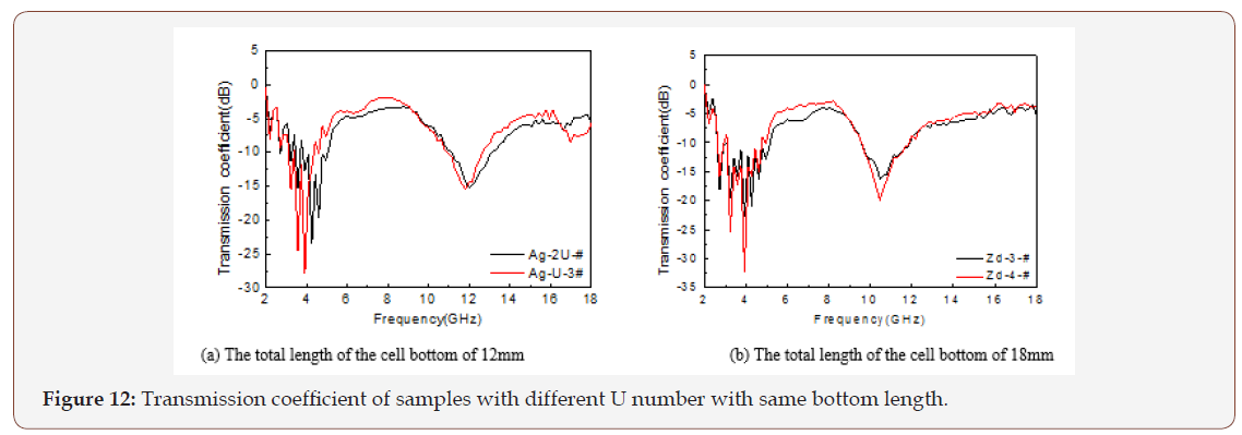
From the experimental data, we can obtain that if the unit total length L is a constant value, the number of U connected elements will hardly affect the resonance frequency. That is to say, the effective unit length L of the FSS is the total length in contact with the U type. According to the characteristic, FSFs with different unit shapes, which are made up of many small U types, can be woven by the tufted carpet loom. The slight movement of the curve in the figure is related to the error of the system and the gap of arrangement.
The same length of single U, the different number of U type
The single-U length was 6mm. With the increase of the number of connected U type, the sample Ag-1U-#, Ag-2U-#, Ag-3U-#, whose unit length were 6mm, 12mm and 18mm respectively, were made. The transmission coefficient curve is studied, and the test results are shown in Figure 13. In the graph, the first resonance frequency of the three curves is around 5GHz, and the second resonance point is in 10-14GHz. The more the number of connected U type is, the smaller the resonance frequency results. Due to the increase of the U-shaped number, the unit total length of the bottom is longer, which is easy to resonate at lower frequency.
Conclusion
In our work, 2D and 3D samples with the same bottom unit length L and 3D samples with different parameters were prepared. Conclusions are drawn as follows: (1) The 3D FSF has the doublefrequency resonance. (2) With an increase of the linear density of conductive yarns, the resonance frequency moves to higher frequency. (3) As inclination angle θ of velvet is larger, the resonance frequency has a trend of decreasing first and then stabilizing. And samples with arbitrary angle inclination reflect electromagnetic wave and do not produce resonance phenomenon. (4) The number of connected U type rarely affects the resonance frequency with the same bottom length L. (5) When the single-U length is the same, the more the number of connected U type is, the lower the resonance frequency results.
Based on the characteristics of lightweight, soft and flexible, the velvet fabric with FSS has a variety of design in aspects of materials, unit sizes and shapes and others. According to the above experimental results, it will be easier to develop the products with specific resonance points. Besides, a large number of experiments are still.
Funding
The authors disclosed receipt of the following financial support for the research, authorship, and/or publication of this article: The authors acknowledge support from the National Natural Science Foundation of China (grant number 51673211).
References
- Birol Y (2008) Production of Al–Ti–B grain refining master alloys from Na2B4O7 and K2TiF6. J Alloys Compd 458: 271-276.
- Whittow W G, Li Y, Torah R, Yang K, Beeby S, et al. (2014) Printed frequency selective surfaces on textiles. J Electron Lett 50(13): 916-917.
- Lee C, Sainati R, Franklin R, Harjani R (2015) Comparative analysis of frequency selective surface geometry effect in Fabry-Perot Cavity antenna design. 2015: 1-4.
- Ebrahimi A, Nirantar S, Withayachumnankul W, Bhaskaran M, Sriram S, et al. (2015) Second-order terahertz bandpass frequency selective surface with miniaturized elements. 5: 761-769.
- Yan M, Qu S, Wang J, Zang J, Zheng L, et al. (2015) Broadband band-pass FSS using patch-wire-patch coupled structures. Advanced Materials and Processes for RF and THz Applications (IMWS-AMP) IEEE: 1-3.
- Chatterjee A, Mandal B, Biswas J, Sarkar G, Saha A (2015) A dual-layer reflective Frequency Selective Surface for wideband applications. IEEE Control Syst Lett: 1-3.
- Liang B, Miao J, Bai M, Xue Z (2015) A novel dual-layer frequency selective surface with grating lobes suppression. Antennas and Propagation & USNC/URSI National Radio Science Meeting IEEE: 1274-1275.
- Izquierdo BZ, Parker EA (2015) Frequency selective surfaces formed by partially metalising 3D printed shapes. Antennas and Propagation (EuCAP) IEEE: 1-4.
- Izquierdo BZ, Parker EA (2014) 3D printed FSS arrays for long wavelength applications. Antennas and Propagation (EuCAP) IEEE: 2382-2386.
- Barton JH, Garcia CR, Berry EA, May RG, Gray DT, et al. (2014) Alldielectric frequency selective surface for high power microwaves. Antennas and Propagation, IEEE 62(7): 3652-3656.
- Xu XX, Wang Q, Tang ZH (2015) Application of frequency selective surface textile material. Safety and Electromagnetic Compatibility (2): 55-58.
- Cavalcante GA, D’Assunção AG Jr, D’Assunção AG (2013) An iterative fullwave method for designing bandstop frequency selective surfaces on textile substrates. Microw Opt Technol Lett 56(2): 383-388.
- Guan F W, Shi M W (2014) Fabrication Method and Application Research of Frequency Selective Fabric (FSF) [C]//The 89th Textile Institute World Conference. Wuhan China, Wuhan Textile University 1015-1019.
- Guan F, Xiao H, Shi M, Wang F (2015) The novel frequency selective fabric and application research. J Industrial Text 11(9): 1-17.
- Seager R D, Chauraya A, Bowman J, Broughton M, Philpott R, et al. (2013) Fabric based frequency selective surfaces using weaving and screen printing. IEEE Control Syst Lett 49(24): 1507-1509.
- Tennant A, Hurley W, Dias T (2012) Experimental knitted, textile frequency selective surfaces. IET Control Syst Lett 48(22): 1386-1388.
- Tennant A, Hurley W, Dias T (2013) Knitted, textile, high impedance surface with integrated conducting vias. IET Control Syst Lett 49 (1): 8-10.
- Chauraya A, Seager R, Whittow W, Zhang S, Vardaxoglou Y (2013) Embroidered frequency selective surfaces on textiles for wearable applications. Antennas and Propagation Conference (LAPC) IEEE: 388- 391.
- Lv ZM, Tang ZH, Xu XX (2014) Preparation and Transmission Characteristics of Flexible Frequency Selective Surfaces. Safety and Electromagnetic (4): 79-81.
- Chauraya A, Whittow WG, Vardaxoglou JC, Li Y, Torah R (2013) Inkjet printed dipole antennas on textiles for wearable communications. IET microw antennas propag 7(9): 760-767.
- Whittow WG, Chauraya A, Vardaxoglou JC, Li Y, Torah R (2014) Inkjetprinted microstrip patch antennas realized on textile for wearable applications. IEEE Antennas Wirel Propag Lett 13: 71-74.
- Cheng H, Xiao H, Shi M, Wang Q, Wang N (2015) Research on 3D periodic structure velvet fabric and its frequency response characteristics. Text Res J 86(7): 776-784.
- Cavalcante GA, D’Assuncao Jr AG and D’Assuncao AG (2014) An iterative full-wave method for designing bandstop frequency selective surfaces on textile substrates. Microwave Opt Technol Lett 56: 383–388.
- Xiao H, Shi MW, Wang Q, Liu Q (2014) The electromagnetic shielding and reflective properties of electromagnetic textiles with pores, planar periodic units and space structures. Text Res J 84: 1679–1691.
- Wu LJ (2013) The influence of the periodic structure unit and physical parameters on the frequency response[D]. Beijing: Beijing University of Technology 31-44.
-
Hong X, Yajing W, Huanhuan C, Meiwu S. Influence Factors of Frequency Response Characteristics for a Novel Velvet Frequency Selective Fabric. J Textile Sci & Fashion Tech. 1(1): 2018. JTSFT.MS.ID.000504.
-
Novel Velvet, Fabric, U-shaped velvet fabric, Frequency selective surface, Influence factors, Frequency response characteristics, Metal aperture, Electromagnetic wave, Conductive fiber, Textile processing, Fabric antenna, Weaving, Knitting, Embroidery, Ink jet printing, Yarn, Velvet height, 3D structure, Carpet, Inclination angle θ
-

This work is licensed under a Creative Commons Attribution-NonCommercial 4.0 International License.


