 Research Article
Braided Rope Sensor Based on Carbon Nanotube Yarn
Yunfei Bai, Qi Xia, Jianghan Feng, Han Liu, Jialin Zheng, Danyao Xu, Sidra Saleemi and Fujun Xu*
College of Textiles, Donghua University, China
Fujun Xu, Associate Professor, College of Textiles, Donghua University, 2999 North Renmin Road, Songjiang District, Shanghai, 201620 PR, China.
Received Date: July 15, 2019; Published Date: July 26, 2019
Abstract
Carbon nanotube (CNT) is exhibited outstanding electrical, mechanical, and structural properties. CNT yarn is widely used in textile structures as multifunctional yarn and is suitable as strain sensor. Here, use two methods for braiding CNT yarn into rope to make sensing ropes. The properties of CNT yarn and different ropes were tested, then according to the result the best method was chosen for the preparation of sensing rope. Results show the CNT yarn have enough strength to be used in braiding process, CNT embedded rope structure has more stable sensing property than CNT braided rope structure. The rope has approximately ≥7% resistance change ratio per 10% strain, so the embedded rope structure is the optimal structure for sensing rope. The sensing rope will help to improve the development of strain sensor in textile structure.
Introduction
Carbon nanotube (CNT) is exhibited outstanding electrical, mechanical, and structural properties, and proved to be an extremely promising candidate for various applications in material science [1-5]. At present, there are three commonly used methods for the preparation of CNT yarns: direct spinning, solution spinning and carbon nanotube array spinning. Carbon nanotube array spinning is the better method to prepare CNT yarns currently [6].
Carbon nanotube yarns are widely used in textile structures as multifunctional yarns. They have piezoresistive effect and can be used as strain sensors [7,8], such as nondestructive testing, which are mainly used for crack propagation of composites. Carbon nanotube yarns can be combined with a variety of materials such as bandages, gloves, socks and so on to monitor and prevent. At the same time, carbon nanotube yarns have excellent mechanical and electrical properties, so they can be used in many fields, such as conductive materials, pressure sensing materials, microstrip antennas and so on.
However, CNT yarns have not been used in rope braiding. Ropes usually need to bear huge force, and their unexpected rupture would bring hidden dangers [9]. If CNT yarn strain sensors are used in ropes, the stress situation of the rope would be observed, and rupture caused by unbearable force would be prevented. But there are many limitations in current CNT yarn preparation methods. Single CNT yarns still have some weaknesses, such as minor diameter, poor abrasion resistance, easy to produce too much hairiness in preparation, so it is difficult to realize industrial application [10].
In order to obtain sensing rope, the CNT film was twisted into a yarn and embedded in the rope to achieve the preparation of the rope sensor. With this process, the CNT yarn could have enough diameter and mechanical properties to be braided in ropes. The optimal braiding structure for sensing rope was also discussed.
Experimental Section
Preparation of CNT yarn
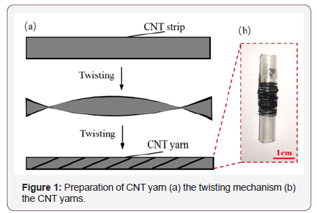
To make a large-diameter and high-strength CNT yarn, twisting a CNT strip to form a composite yarn. The diameter, twist angle and CNT volume fraction of the yarn are controllable by adjusting the film strip’s width and twisting process. In addition, the twisting process provides shear force, which improves the yarn’s surface orientation.
Figure 1a shows the schematic diagram of twisting process. Here’s the operation steps: Cut the CNT film into strips. Set the rotating speed of the twisting motor. Fix both ends of the strip to prevent untwisting. Then start the twisting machine for yarn preparation. Figure 1b shows the CNT yarn.
Braiding of the sensing rope
There are two main methods to achieve the braided rope with CNT yarn in it: CNT braided process and CNT embedded process.
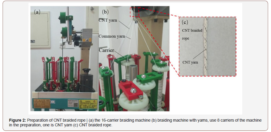
For the CNT braided process, CNT yarn is interwound cyclically with other common yarns to be braided into the rope. Use a braiding machine (Figure 2a) to prepare the rope. In the process, one of the braiding yarns is CNT yarn and the other are common yarns (Figure 2b). The position of braiding point should be controlled, or the rope would be inhomogeneous. Tension of the braiding yarns needs adjustment during the braiding process, in order to prevent the CNT yarn’s elongation. To adjust the tension, pause the machine and rotate the carrier. Figure 2c shows the CNT braided rope.
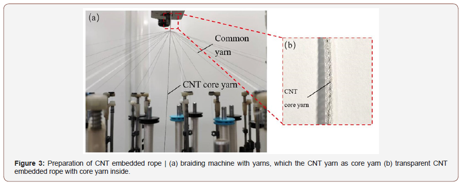
For the CNT embedded process, 8 yarns are braided into a rope as the outer layer and the CNT yarn is embedded into the rope as a core yarn. In the process, put common yarns on the carriers of the braiding machine and CNT yarn as the core (Figure 3a). A pretension on CNT yarn is necessary, in order to keep it straight. The CNT yarn would be embedded into the rope during the braiding process. To show the inner structure of the rope, use transparent nylon yarn as braiding yarn. Figure 3b shows the CNT embedded rope, it’s clear that CNT core yarn is straight in the transparent rope.
Results and Discussion
Structure of the CNT yarn
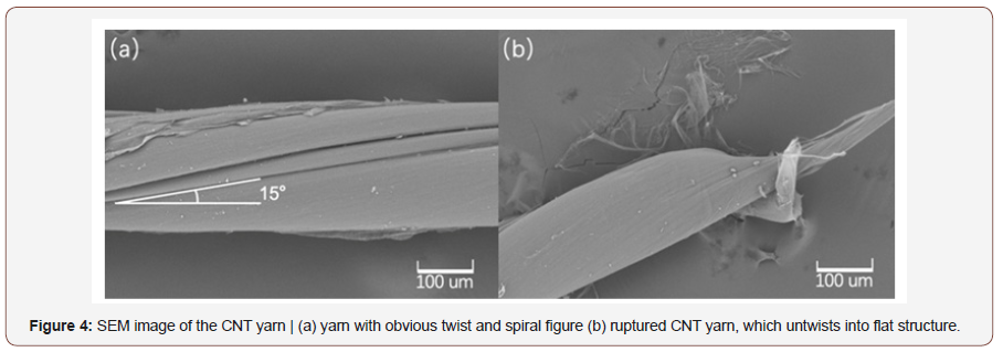
With the twist of 6/cm, the CNT yarn is obtained by single untwisted CNT film, which the width is 5mm. As shown in Figure 4a, the SEM image of the twisted CNT yarn, from which it can be seen obviously that twist and spiral of the CNT yarn. The diameter of the yarn is quite uniform at 220μm and the twist angle of the CNT yarn is about 15°.
After rupture, stress relaxation occurred inside the yarn and fiber in the yarn slipped, thus the CNT yarn is untwisted and converted back into CNT film (Figure 4b). According to the comparison of Figure 4a with Figure 4b, the CNT yarn is transformed from uniform cylindrical smooth structure to broad flat structure.
Mechanical property of the CNT yarn
As shown in Figure 5, the maximum strain at fracture of the twisted CNT yarn is 20%, and the stress increases to 80 MPa, these values of strength are higher than the values of traditional CNT yarns.
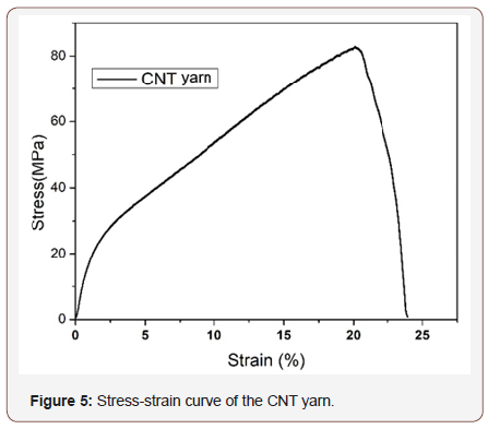
The good mechanical properties of the CNT yarns should be attributed to the action of twisting, which acts in two ways. First, the twisting process fills the internal spaces inside yarn and increases volume content, so the compact structure achieved. Second, the shear force caused by twisting improves the orientation of carbon nanotube arrangement.
Because of the good mechanical properties, this CNT yarn can be used in rope braiding process.
Sensing performance of the CNT yarn
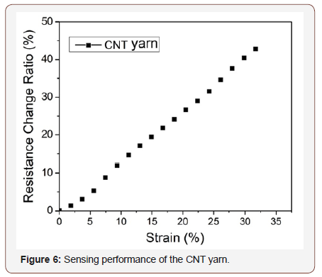
The resistance change rate of the CNT yarn in the strain range of 35% is obtained by sensing performance test, in which the Y-axis is the resistance change rate and the X-axis is the strain (Figure 6). The result shows that the curve is smooth, and there is a good correspondence between strain and resistance change ratio, which is about 12% resistance change per 10% strain. In the same strain condition, the resistance change ratio of twisted CNT yarn is higher than that of traditional CNT yarn.
Optimization of the braiding processes
The sensing performance of the two different structure ropes was tested. Figure 7a shows the sensing performance of the CNT braided rope: as the strain increases, the resistance change rate fluctuates significantly, and comparing to the CNT yarn, the linearity is affected to obvious extent. The main reason is that the carbon nanotube yarn generates buckling during the braiding process, and when the rope is stretched, the CNT yarn itself not only is elongated, but also suffers the pressing effect of the nearby yarns, so the fluctuation is significant. In addition, the sensing performance will be further affected due to the direct exposure of the sensing yarn to the complex application environment.
Figure 7b shows the sensing performance of the CNT embedded rope: compared with the CNT braided rope, the rope with the CNT core yarn embedded in it has a moderate fluctuation in the resistance change ratio, the sensing performance is improved because the sensing yarn in the rope keeps straight and is not subjected to obvious buckling. The rope’s resistance change ratio is approximately ≥7% per 10% strain, which is obviously lower than single CNT yarn, but it is enough to reflect the rope’s elongation.
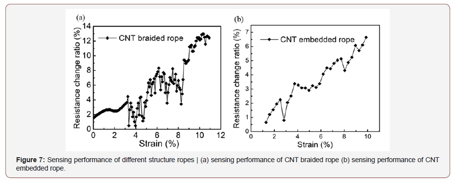
After comparison between 2 braiding process, it’s obvious that CNT embedded structure is the better structure for rope sensor based on CNT yarn.
Conclusion
In summary, prepared CNT yarn with good properties as strain sensor, then realized the combination of CNT yarn sensor and braiding rope. Compared different braiding process and chose the optimal one. Finally, prepared braided rope sensor based on CNT yarn.
Twisted CNT strip into sensing yarn. Observed the yarn’s structure, tested its mechanical properties and sensing performance. The yarn has 220μm diameter, 80MPa strength and good breaking elongation as 20%. As a result, this CNT yarn is suitable for rope braiding. The sensing performance test showed that there is a good correspondence between its strain and resistance change ratio, which is about 12% resistance change per 10% strain. So, it can be used as a strain sensor.
After that, used two different methods to braid rope sensor with CNT yarn and other common yarns, then compared their sensing performance in order to choose an optimal structure for rope sensor. Results showed that CNT embedded rope structure had more stable sensing property than CNT braided rope structure. The rope has approximately 7% resistance change ratio per 10% strain, which is enough to observe its elongation, so it’s practical to use CNT yarn in braided rope. The sensing rope will help to improve the development of strain sensor in textile structure.
Acknowledgement
None.
Conflict of Interest
Authors declare no conflict of interest.
References
- (1999) Recent advances in the chemistry and physics of fullerenes and related materials. Kamat KV, Guldi DM, Kadish KM (edts), The Electrochemical Society, USA, 5(97–42): 549-560.
- Yu MF, Lourie O, Dyer MJ, Moloni K, Kelly TF, et.al. (2000) Strength and breaking mechanism of multiwalled carbon nanotubes under tensile load. Science 287(5453): 637-640.
- Iijima S (1991) Helical microtubules of graphitic carbon. Nature 354: 56-58.
- Liu W, Xu F, Zhu N, Wang S (2016) Mechanical and Electrical Properties of Carbon Nanotube/Polydimethylsiloxane Composites Yarn. Journal of Engineered Fibers and Fabrics11(4): 36-42.
- Oland E, Rune S, Shaun F (2017) Condition monitoring technologies for synthetic fiber ropes-a review. International Journal of Prognostics and Health Management 8(2): 14-15.
- Frackowiak E, Beguin F (2002) Electrochemical storage of energy in carbon nanotubes and nanostructured carbons. Carbon 40(10): 1775- 1787.
- Lipomi DJ, Vosgueritchian M, C-K Tee B, Hellstrom SL, Lee JA, et al. (2011) Skin-like pressure and strain sensors based on transparent elastic films of carbon nanotubes. Nature Nanotechnology 6: 788-792.
- Baughman RH, Zakhidov AA, de Heer WA (2002) Carbon Nanotubes--the Route Toward Applications. Science 297(5582): 787-792.
- O’donnell HJ, Hoffman TJ, Barker FH (2000) Rope tension monitoring assembly and method: US Patent 6,123,176[P].
- Baughman RH, Cui C, Zakhidov AA, Iqbal Z, Barisci JN, et al. (1999) Carbon nanotube actuators. Science 284(5418):1340-1344.
-
Fujun Xu, Yunfei Bai, Qi Xia, Jianghan Feng, Han Liu, et al. Braided Rope Sensor Based on Carbon Nanotube Yarn J Textile Sci & Fashion Tech. 3(3): 2019. JTSFT.MS.ID.000562.
-
Braided rope, Sensor, Carbon nanotube, Yarn, Textile, Composites,
-

This work is licensed under a Creative Commons Attribution-NonCommercial 4.0 International License.


