 Research Article
Finite Element Analysis and Calculation of Normal Section Bearing Capacity of Steel Tube Bundle Composite Shear Wall
Zeng Ling Jiang, School of civil engineering and architecture, wuyi university, China.
Received Date: December 15, 2018; Published Date: January 11, 2019
Abstract
To be a new type of building component, composite shear wall with steel tubes bundle has been widely used in the steel structure housing system as the development of prefabricated construction. In this paper, ABAQUS has been used to analyze mechanical performance of composite shear wall under low cycle reciprocating loading conditions. 6 group simulations with different axial compression ratio have been carried out, and both hysteretic curve and skeleton curve have been drawn. The simulation results showed that hysteretic curves become full before composite shear wall damage, and seismic performance is good. When the axial pressure ratio is 0.2, the bearing capacity of composite shear wall with steel tubes bundle achieves its maximum value. The bearing capacity of composite shear wall with steel tubes bundle also was calculated using classical shear wall formulation, the results are consisting with finite element simulation.
Keywords:Composite shear wall with steel tubes bundle; Axial pressure ratio; Normal section bearing capacity; Finite element analysis
Nomenclature
N- the axial pressure applied vertically
Nc- the vertical load borne by the concrete in the vertical compression zone
Β- the conversion coefficient of stress curve, which is 0.85
Ayhc and Ayvc- the area of the compression steel plate parallel to the force plane of the combined shear wall
Ayht and Ayvt- the area of the tensile steel plate parallel to and perpendicular to the combined shear wall of the steel tube bundle
fy- the yield strength of steel
fc- the standard value of axial compressive strength of concrete
b- wall thickness; t is thickness of steel plate
h- the length of the wall
n1 and n2- respectively the number of stiffened and stiffened ribs perpendicular to the force plane of the combined shear wall of the steel tube bundle
dyhc and dyvc- respectively the distance from the resultant point of the compression steel plate to the centroid of the shear wall which is parallel to and perpendicular to the stress plane of the combined shear wall of the steel tube bundle
dyht and dyvt- respectively the distance from the resultant point of the tensile force of the steel plate to the centroid of the shear wall which is parallel to and perpendicular to the stress plane of the combined shear wall of the steel tube bundle
Ac- he section area of concrete
As- the section area of steel plate
fc,d- the design value of compressive strength of concrete shaft
fy,d- the design value of compressive strength of steel plate
fc,t- the measured compressive strength of the concrete axis
fy,t- the measured yield strength of steel
Introduction
In recent years, China’s housing industry has been further accelerated under the background of the national promotion of prefabricated buildings, and various new structural systems have emerged. Steel plate shear wall mainly includes four forms at present, steel reinforced concrete composite shear wall, steel plate shear wall, single steel plate shear wall, double steel plate shear wall.
Tong, et al. [1] conducted the casing outside the i-steel filled concrete wallboard composite shear wall low reversed cyclic loading test, the test shows that fills in wall body responsible for 80% of the horizontal load, the steel frame for 80% of the overturning moment, in the process of the test concrete wall crack first, then the steel frame to yield, the final damage is due to concrete crushed wall corner. Soon H C and Bryce T conducted low-cycle repeated load tests on reinforced concrete shear walls with steel tube, channel steel, bolt and concrete edge members on both sides of the wall and compared the seismic performance of different forms of shear walls. Jiaru Qian [2] has carried out the pseudo-static test study on the shear wall of concrete-filled steel tube in six restrained edge members, which shows that the ultimate failure mode of the shear wall is bending failure and the concrete collapse at the bottom. The bearing capacity and deformation properties of this shear wall are larger than those of reinforced concrete shear wall with the same parameters.
Jinyu Lu, et al. [3] made four 1/3-scaled test specimens that are designed for the experimental study. Two of the specimens are steel plate shear walls with slits (SPSWUSs), and the other two are traditional SPSWSs. Testing of the system were performed under cyclic lateral loading. Results show that SPSWUS has rather high energy dissipation capacity and good ductility as well as relatively high lateral stiffness and ultimate bearing capacity when compared with the tradition SPSWS. Experimental results correlate well with those from the finite element analysis, which validates the finite element model.
Zhao Q, et al. [4] put forward a new combined shear wall of precast reinforced concrete slabs. The precast concrete slabs are suspended on both sides of the steel plate through shear bolts. According to whether there is a certain gap between the concrete wall slabs and the surrounding beams and columns, they are divided into traditional and improved forms. As for the improved composite shear wall of steel plate, the concrete wall plate only plays the role of restraining the external buckling of steel plate at the early stage of load loading. With the increase of displacement, the concrete wall plate starts to work together with the steel plate to control the deformation and improve the bearing capacity at the later stage of the structure.
Emori [5] carried out compressive and shear tests on 1/4 scale double-plate shear walls with longitudinal and transverse stiffeners. The results show that the ductility and bearing capacity of the shear walls are very good. The results of shear tests are compared by finite element analysis, and the bearing capacity formula of the shear walls is derived. Clubley, et al. [6] and others studied Bi-Steel composite shear wall. The shear wall was connected with concrete by horizontal shear bond between two steel plates. 12 shear walls with different steel plate thickness, shear bond spacing, steel plate spacing, and other parameters were tested. The strength of local steel plate was calculated by numerical simulation. The strain of steel plate and shear bond is analyzed. Suggestions for the selection of plate spacing and thickness are put forward.
As a new structure form, it is necessary to analyze its mechanical properties. This paper mainly deduces the bearing capacity formula of the normal section of the steel tube bundle composite shear wall and establishes the finite element model corresponding to the actual situation under the different axial pressure ratio to verify the correctness of the formula. The results of finite element analysis show that the composite shear wall with steel tube bundle has full hysteretic curve, good ductility and good seismic performance within the range of bearing capacity.
Establishment of Finite Element Model
Selection of constitutive model
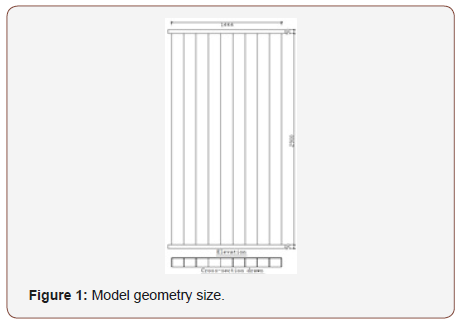
The geometric dimensions of the model are shown in Figure 1. The steel plate of steel tube bundle shear wall adopts Q345. The steel plate material property is selected according to the literature [7], and the yield strength of steel plate is 345MP. The concrete strength grade is C50, and the standard values of axial compressive strength and axial tensile strength are fck = 41Mpa , 3.1 ftk = Mpa respectively according to the specification. The constitutive model adopts the plastic damage model of concrete [8].
Contact model and boundary conditions
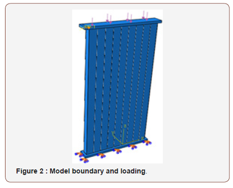
The contact between steel tube and concrete is limited slip, the tangential friction coefficient is 0.4, and the normal is hard contact. Both steel pipe and concrete are simulated by solid units, and the steel pipe and upper and lower cover plate are bound. Low cyclic reciprocating load is applied on the horizontal direction of the upper end platen, and uniformly distributed load is applied on the upper end cover plate to achieve the bearing capacity of the composite shear wall made of steel tube bundle concrete under different axial pressures, while the lower end cover plate is the fixed end. The boundary condition and loading method of the model are shown in Figure 2.
Loading system
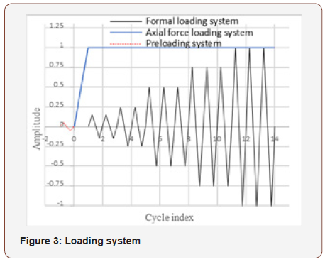
The loading system is divided into two modes: preloading and formal loading. The preloading of finite element is to enable the finite element contact conditions and stress to be smooth and orderly and avoid the calculation interruption caused by the nonconvergence of the results. The loading system is shown in Figure 3.
Formula for Calculating the Bearing Capacity of Normal Section
The section stress distribution of the composite shear wall with steel tube bundle conforms to the assumption of flat section [9], so the bearing capacity analysis can be conducted according to the assumption of flat section. According to the balance equation, ΣN = 0, ΣN = 0 can be obtained. The following is the calculation model of the formula for calculating the bending bearing capacity of shear wall.
The vertical force is balance:

Vertical load bearing on concrete compression zone Nc:

By (1), (2) and substituting the corresponding dimensions, the following formula can be obtained:

The height of concrete compression zone obtained from equation x is:

The moment of wall section center is obtained:

From the formula (4) and (5) and substituted into the corresponding dimensions, we can get:

The Finite Element Results are Compared with the Calculated Values of The Formula
Calculation of axial pressure ratio
The bearing capacity and ductility performance of the components are affected by the axial compression ratio. According to the technical regulations of the concrete structure of high-rise building:
Design the calculation formula of axial pressure ratio:

Calculation formula of actual axial pressure ratio:

In the case that other parameters remain unchanged, different axial forces are applied to the model to change the axial pressure ratio to study the impact on the seismic performance of the composite shear wall of steel tube bundle concrete. In the case of different axial compression ratios, the hysteretic curve of steel tube bundle composite shear wall under low circumferential counterload is shown in Figure 4. The axial force in Table 1 is obtained by using the calculation formula of the actual axial pressure ratio.
Hysteretic curve
The curve of hysteresis curve is the curve between force and displacement obtained under low cyclic repeated loading. The hysteretic curve of Figure 4 is obtained under the loading system of Figure 3. At the initial stage of loading, the hysteretic curve under different axial compression ratios is a straight line, and the shear wall of steel tube bundle is in the elastic stage. Before reaching the peak load, the hysteretic curve is fusiform, full in shape, without pinching. It can be seen from Figure 4 that as the axial pressure ratio increases, the squeeze spindle phenomenon of hysteretic curve becomes more and more obvious. When the axial compression ratio reaches 0.5, the hysteretic curve takes on a “Z” shape, indicating that the concrete and steel plate have relatively obvious slip. When the axial compression ratio is 0.6, the hysteretic curve appears obvious disorder, indicating that the concrete is crushed, the steel plate yields, and the steel tube bundle composite shear wall fails.
Skeleton curve
It can be seen from Figure 4 and Figure 5 that the axial compression ratio has a certain influence on the bearing capacity of the composite shear wall with steel tube bundle. When the axial pressure ratio is between 0.1 and 0.2, the axial pressure ratio has no effect on the composite shear wall of steel tube bundle, and the skeleton curve is nearly coincident. When the axial pressure ratio is less than or equal to 0.3, the skeleton curve is slow and ductile. When the axial pressure ratio is greater than or equal to 0.4, the skeleton curve has a relatively obvious drop section, and the bearing capacity also has a corresponding decline. When the axial pressure ratio increased from 0.3 to 0.4, 0.5 and 0.6, the horizontal peak load decreased by 8%, 25% and 54% compared with that when the axial pressure ratio was 0.3, and the horizontal load decreased rapidly.
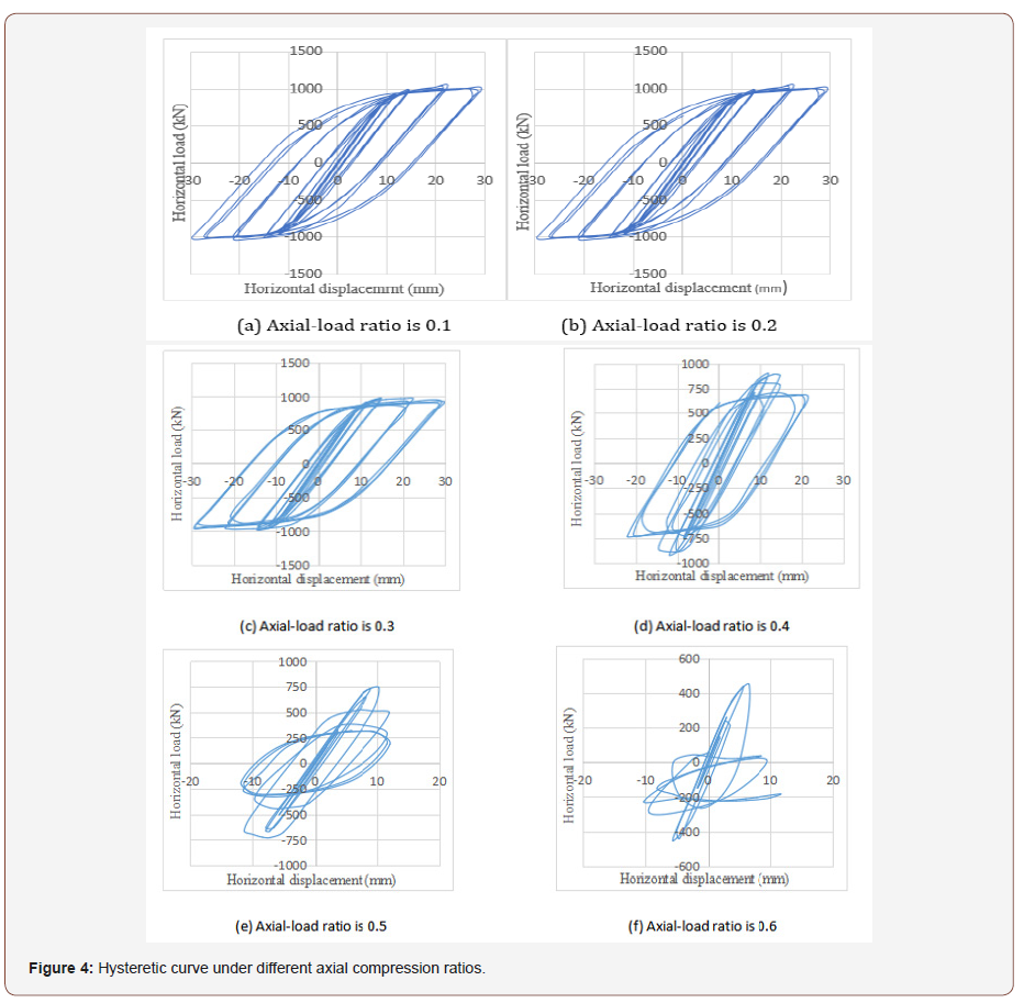
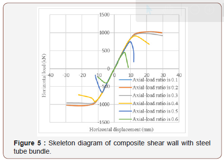
Table 1:Calculation results for different axial compression ratios.

Conclusion
1. Through ABAQUS finite element software, the finite element analysis model of composite shear wall with steel tube bundle was established, and the mechanical properties of composite shear wall with steel tube bundle were analyzed under different axial compression ratios. The results of finite element analysis and formula calculation show that the bearing capacity of composite shear wall with steel tube bundle is the maximum when the axial pressure ratio is 0.2, and the bearing capacity decreases rapidly when the axial pressure ratio is greater than 0.2 (Chart 1).
Chart 1:Composite shear wall parameters of steel tube bundles of different thickness.

2. The results show that the finite element values agree well with the calculated values of the formula. It is verified that the formula is applicable to the calculation of normal section bearing capacity of combined shear wall with steel tube bundle.
3. The finite element model can accurately simulate the working mechanism of the composite shear wall of steel tube bundle and can provide a basis for the actual engineering design and application of the composite shear wall of steel tube beam.
Acknowledgement
None.
Conflict of Interests
No Conflict of Interest.
References
- Tong X, Hajjar JF, Schultz AE, Shield CK (2005) Cyclic behavior of steel frame structures with composite reinforced concrete infill walls and partially-restrained connections. Journal of Constructional Steel Research 61(4):531-52.
- Qian J, Jiang Z, Ji X (2012) Behavior of steel tube-reinforced concrete composite walls subjected to high axial force and cyclic loading. Engineering Structures 36:173-84.
- Lu J, Yu S, Xia J, Qiao X, Tang Y (2018) Experimental study on the hysteretic behavior of steel plate shear wall with unequal length slits. Journal of Constructional Steel Research 147:477-87.
- Zhao Q, Astaneh-asl A (2004) Cyclic Behavior of Traditional and Innovative Composite Shear Walls. Journal of Structural Engineering 130(2):271-84.
- Katsuhiko E (2002) Compressive and shear strength of concrete filled steel box wall. Steel Structures 26(2):29-40.
- Clubley SK, Moy SSJ, Xiao RY (2003) Shear strength of steel–concrete– steel composite panels. Part I-testing and numerical modelling. Journal of Constructional Steel Research 59:781-98.
- (2015) Techinical specification for steel structures in high-rise civil buildings. Beijing: China building industry press.
- Lee J, Fenves GL (1998) Plastic-damage model for cyclic loading of concrete structures. Journal of Engineering Mechanics 124(8): 892.
- Zhang Xm (2016) Seismic performance test and theoretical study of steel tube bundle composite shear wall [D]: Tianjin University.
-
Zeng Ling Jiang. Finite Element Analysis and Calculation of Normal Section Bearing Capacity of Steel Tube Bundle Composite Shear Wall. Glob J Eng Sci. 1(3): 2019. GJES.MS.ID.000512.
-
Composite shear wall with steel tubes bundle, Axial pressure ratio, Normal section bearing capacity, Finite element analysis, Wall thickness, Yield strength of steel, Steel tube bundle, Concrete shaft, Finite element, Bearing capacity, Concrete compression zone, Axial-load ratio
-

This work is licensed under a Creative Commons Attribution-NonCommercial 4.0 International License.


