 Research Article
Analysis of Possible Risks in Aviation Safety Issues Associated with the Massive Introduction of Unmanned Aerial Systems
Salwa FEZAI1*, Racha NEFZI2 and Brahim BEN-BEYA2
1Physics Department, Samtah University College, Jazan University, Kingdom of Saudi Arabia
2Laboratory of Physics of Fluids, Physics Department, Faculty of Science of Tunis, University of Tunis El-Manar, 2092 El-Manar 2, Tunis, Tunisia
Salwa FEZAI, Physics Department, Samtah University College, Jazan University, 45142 Jazan, Kingdom of Saudi Arabia.
Received Date: December 21, 2020; Published Date: January 07, 2021
Abstract
The flow around three staggered square cylinders at two different triangular arrangements has been numerically analyzed in the present work. The calculations are carried out for several values of Reynolds numbers ranging from 1 to 110. Three different states of flow are found in this study by systematically varying Re. The critical Reynolds number is determined for both two arrangements. It is clear that the point of bifurcation is strongly influenced by the type of the type of the triangular arrangement because both arrangements generate a large reduction in the value of the critical Reynolds number. The unsteady periodic wake is characterized by the Strouhal number, which varies with the Reynolds number and also the arrangement of the three cylinders. Hence, the values of vortex shedding frequencies are calculated for both triangular arrangements. Furthermore, the drag and lift coefficients of three staggered squares cylinders in different triangular arrangements are determined.
Keywords:Staggered square cylinders; Flow regimes; Triangular arrangement; Strouhal number; Numerical simulation; Critical Reynolds number; Lift and drag coefficients
Nomenclature:
Re - Reynolds number
l - channel width
h - channel height
(u, v) - velocity components, m s-1
x, y - dimensionless coordinates
St - Strouhal number
CD - drag coefficient
CL - lift coefficient
P - dimensionless pressure
Φ - generic variable
Greek symbols
ρ - density of fluid, kg m-3
ν - kinematic viscosity, m2s-1
Subscripts
Max, Min - maximum, minimum
c - Critical
Introduction
The examination of flow structures around staggered cylinders at different arrangements is important because many issues related to aerodynamics are placed in category of these types of flow and in many applications. High-rise buildings, bridge piers, chimneys, wind tunnel, cooling towers are examples of these applications. However, three or more square cylinders make the problem complicated due to the interaction between shears layers and shedding vortices in the wake region. For this reason, many investigations on the flow around cylinders with variety of arrangements have been done. Indeed, the wake development behind these configurations depends on Reynolds number, spacing between obstacles and the structure of arrangement. Thus, it is important to understand the dramatic change in the wake structure. Therefore, many numerical investigations are available related to the characteristics of flow around two or more bodies in different arrangements. For better understanding of the phenomenon of Hop bifurcation, one can refer to the investigation of Yang and Zebib [1]. They showed that when the Reynolds number of about 20, an absolutely unstable region begins to form, and grows more and more with Re. Furthermore, they deduced that the critical Reynolds number corresponds to a state where all wake is absolutely unstable.
Fezai et al. [2] also examined the transition from a symmetric flow state to the periodic state. They analyzed the vortex at different arrangements of the two shapes. The analysis of the flow evolution shows that with increasing Re beyond a certain critical value, the flow becomes unstable and undergoes a bifurcation. Therefore, they observed that the transition to unsteady regime is performed by a Hopf bifurcation.
The appearance criteria of different regimes such as crawling
scheme, the steady and unsteady with releases of vortices strongly
depends on the Reynolds number, so this conclusion was drawn
by Berrone et al. [3]. They also found that the results of numerical
studies strongly depend on the choice of the mesh refinement, the
passage of time and the domain size. This is well confirmed by the
work of Noack and Eckelmann [4]. They found that for all Reynolds
less than 54 the flow is stable, while the periodicity appears for 54
The transitions in the wake of a square cylinder were also investigated
by Gera et al. [5]. They found that the flow around a single
square cylinder remains steady up to Re = 50 and instability occurs
between Re = 50 and 55. After this range, flow becomes completely
unsteady. Similar observations were reported in the numerical
work of Kelkar and Patankar [6]. They concluded that the point of
instability is between Re = 50 and 60 and they computed the value
of the critical Reynolds number having a value Rec=53. Lankadasu and Vengadesan [7] analyzed numerically incom
pressible linear shear flow across a square cylinder. They found
that the critical Reynolds number is reduced with increasing shear.
Their results show that the mean drag coefficient decreases either
with increasing shear for a particular Reynolds number or with increasing
Reynolds number for a particular shear parameter. In the work of Cheng et al. [8], it was reported that that the vortex
shedding and wake development behind the square cylinder
are significantly dependent on both the magnitude of the shear rate
and the Reynolds number. Indeed, they found that vortex shedding
disappeared for large shear parameters. The frequency of vortex
shedding decreases as the shear parameter increases. Also, the
drag coefficient tends to decrease with increasing shear parameter. Mukhopadhay et al. [9] analyzed the structure of a flow around
a square obstacle for different Reynolds number and for different
positions of the obstacle. These researchers analyzed the effect of
blockage ratio on the variation of Strouhal number based on the
Reynolds number. In all cases, the Strouhal value increases with the
blocking ratio and undergoes a slight change with increasing Re.
Consequently, they determined the critical Reynolds number from
which the flow becomes periodic and they concluded that the frequency
starts at Re = 87 for a blockage ratio B/H = 0.25. When two cylinders are placed in line, the flow characteristics
could be substantially different from those of single cylinder due
to interactions of the wakes of the two cylinders. Vikram et al. [10]
examined the flow around two tandem square cylinders. They reported
that the vortex shedding frequency was suppressed due to
introduction of second square cylinder. Abbasi and Islam [11] simulated wake interactions of a flow
around two square cylinders which are placed in line with a fixed
space ratio equal to 3.5. They concluded that the unsteady regime
appears when the Reynolds number reaches the value 55. Recently, Burattini and Agrawal [12] analyzed the flow around
two square cylinders at a Reynolds number of 73. They reported
different ranges of the wake flow regimes. Rao et al. [13] investigated the effect of the space ratio on the
flow around two square cylinders arranged side by side. They found
that the frequency of vortex shedding is different in two wakes. The
upper frequency is smaller than the lower frequency for small rations
(s<1.4). However, when the space rations increase, the frequency
of vortex shedding is almost equal in two wakes. They analyzed
the influence of the space ration and Reynolds number on
the drag and lift force. The difference of time-averaged drag and lift
coefficients of the cylinders decreases with the increase in space ratios.
When s=2.0 and 2.5, the curves for the time averaged drag and
lift coefficient with different Reynolds numbers are smooth. Also,
they reported that when s=1.5 and 1.8, the curves are smooth under
Re<140, but that will be fluctuant under Re>140 because of the
nonlinear interaction between the wakes and the instability of flow
becomes stronger with the increase in Reynolds numbers. Adeeb et al. [14] investigated computationally the wake flow of
two square cylinders by varying the corner radius to understand
the effect of the gap spacing’s role and the wake flow pattern at Re
= 100. They found that the flow characteristics and vortex shedding
depend significantly on the corner radius and gap spacing. They
concluded that a square cylinder exhibited the maximum average
drag value and the inverse was observed in the case of a circular
cylinder. Furthermore, aerodynamic forces were reduced by rounding
the corner radius. Aboueian and Sohankar [15] examined the effect of the gap
spacing on the flow over two square cylinders in staggered arrangement
at Re=150. By changing the gap spacing between cylinders,
five different flow regimes are identified and classified. Investigations of flow characteristics of a row of square cylinders
arranged in side-by- side configuration also attracted a considerable
amount of interest in the past. Abbasi et al. [16] have
conducted an investigation on the transition in flow states around
two-, three- and four-inline square cylinders the effect of Reynolds
numbers at two different gap spacing g = 2 and 5. Their results
show that at g = 2, the range of Re for each flow state decreases by
increasing the number of cylinders in the array, while at g = 5, they
observed the opposite trend. Hetz et al. [17] have also found that
the Strouhal number of five inline circular cylinders increases with
increment in g. Manzoor et al. [18] reported that, at some spacing
values, the downstream cylinders experience larger drag force as
compared to upstream cylinders due to turbulence effects in flow
even at low Re values. Liu [19] examined the dependence of flow
induced forces on g and found that the drag coefficient (CD) of cylinders
changes abruptly in the range between g= 3.5 and 4 due to
existence of critical spacing value in this range. Also, Zheng et al. [20] examined the effect of gap ratios ranging
from 1.5 to 7 and two incidence angle ɵ= 0° and 180° on flow
past three circular cylinders arranged in an equilateral triangular
arrangement. They found that the proximity interference dominated
the flow interference among three cylinders at small gap spacing
g. At intermediate g, the gap flow became intense, weakening the
proximity interference, while the impact of the proximity effect became
very weak and wake effects dominate the flow interference
among three cylinders at sufficiently large gap spacing. They also
reported that for small g the fluctuating forces on downstream cylinders
are very small and far less than those on a single cylinder
due to the proximity effect. Yang et al. [21] analyzed numerically the flow pattern and vortex
suppression regions for three circular cylinders with two different
staggered arrangements. In the first arrangement a primary cylinder
was placed in front of downstream two side by side cylinders
and in the second arrangement a primary cylinder was placed in
the wake of upstream two side by side cylinders. Their results show
that in the first arrangement, the vortex shedding behind the primary
cylinder was suppressed by the downstream two side by side
cylinders at 100≤Re≤200. They also reported that in the second
arrangement the vortex shedding of the primary cylinder was suppressed
by the upstream two side by side cylinders at 103≤Re≤175. We can also mention the work of Yang et al. [22]. They arranged
three stationary circular cylinders in such a way that one cylinder
was placed in front of two side by side cylinders and investigated
the effect of the gap ratio in the range from g=1-10 for Re=200.
They observed steady flow region at 1≤g≤1.2 and 2.5 ≤g≤3.1 and
unsteady flow region at 1.3≤g≤2.4 and 3.2≤g≤10. They also found
regular drag and lift coefficient in steady flow region which became
irregular in unsteady flow region. Bao et al. [23] investigated the flow past an inline array of six
square cylinders at Re = 100 and ranging from 1.5 to 15. They observed
six different kinds of flow patterns: steady wake, non-fully
developed vortex street in single row and double-row, fully developed
vortex street in double-row, fully developed vortex street in
partially recovered single-row, and fully developed multiple vortex
streets. They also observed that the first and second cylinder behave
similar to the two inline cylinders configuration in terms of
aerodynamic force coefficients while the other four cylinders experience
periodic variation of forces with the increase in gap spacing. The literature survey shows that not much attention has been
paid to the flow around square cylinders in triangular arrangement.
This type of flow has not been examined yet for a wide range of
Reynolds number and global parameters are not fully investigated.
In the numerical work of Rahman et al. [24], the value of the
critical Reynolds number, which characterizes the bifurcation point
from steady state to unsteady sate, has not been determined and
they have limited their work to a single value the Reynolds number
which has been set at 150. However, this limitation is not there in
this work. Therefore, in this paper, we will focus on the flow around three
square cylinders at two different types of triangular arrangements.
The motivation of current study is to determine the exact value of
the critical Reynolds number for both arrangements and analyze
the effect of changing the arrangement of the three square cylinders
on the vortex shedding and on the drag and lift forces in order
to analyze the flow structure around two different arrangement at
steady, transitional and unsteady states. The first task is essentially composed of six parts. Firstly, we
present the configuration of the physical problem. The second part
is devoted to presentation of equations and boundary conditions.
The numerical method used for solving the system of Navier-Stokes
equations in its dimensionless form in the case of a two-dimensional
(2D) incompressible flow is presented in the third part. The
fourth part is dedicated to the validation of the numerical in-house
code used and followed finally by results and discussions. The fifth
part is consecrated for results and discussions. Finally, we will draw
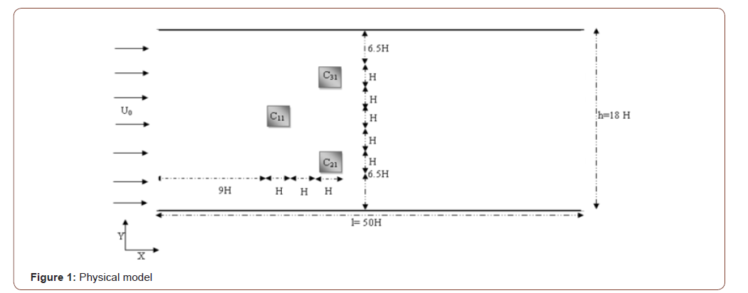
conclusions from this study in a final part. The geometry of the problem of this particular study consists
of a two-dimensional flow of a Newtonian incompressible fluid
around three staggered square cylinders situated in a channel having
a width l = 50H and a height h = 8H as sketched in Figure 1. In the present study, two configurations will be considered by
varying the arrangement of the three cylinders C1, C2 and C3. For
the first arrangement, the configuration is composed of three cylinders
C11, C21 and C31 as shown in the figure, but in the second configuration
the arrangement of the three cylinders will be reversed
from the first configuration. In Figure 2 we have schematized the
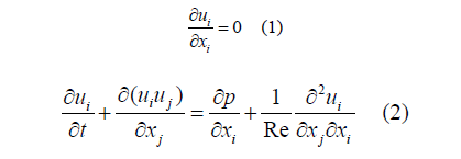
two arrangements that we will study and analyze. The physical problem is governed by the Navier–Stokes equations
for two-dimensional incompressible fluid flow. The continuity
and momentum equations are written in dimensionless form expressed
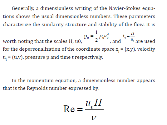
as follows: Generally, a dimensionless writing of the Navier-Stokes equations
shows the usual dimensionless numbers. These parameters
characterize the similarity structure and stability of Where ue= u0 is the velocity upstream, H is the side of the barrier
ν and is the kinematic viscosity of the fluid under consideration. The boundary conditions for this physical problem are as following: • At the channel entrance: The horizontal u- velocity component has a uniform form u0 = 1
The vertical component of the velocity v is set to zero. • On the obstacle, non-slip conditions are imposed; u = 0
and v = 0 • At the exit of the channel: The convective condition [25]
is written as follows: The dimensionless Navier-Stokes equations were numerically
solved utilizing the following numerical technique based on the finite
volume method [26]. The temporal discretization of the time
derivative is performed by a Euler backward second-order implicit
scheme. Nonlinear terms are evaluated explicitly; then, viscous
terms are treated implicitly. The strong velocity–pressure coupling
present in the continuity and the momentum equations is handled
by applying the projection method [27]. A Poisson equation, with
the divergence of the intermediate velocity field as the source term,
is then computed to obtain the pressure correction and the real velocity
field. A finite volume method was utilized on a staggered grid
system in order to discretize the system of equations to be solved.
Furthermore, the QUICK scheme of Hayase et al. [28] is applied to
minimize the numerical diffusion for the advective terms. The discretized
equations are computed utilizing the red and black point
successive over-relaxation method [29] with the choice of optimum
relaxation factors. Besides, the resolution of the Poisson equation is
performed by applying an accelerated full multi-grid method [30]. The construction of the mesh is the first step in any numerical
simulation. The used meshes in this investigation are based on a
staggered grid where scalar quantities (pressure...) and located at
the center of the cell, while, the velocity components are defined at
the centers of faces of the volume controls. In order to ensure accuracy, the grids have denser clustering
at the vicinity of the barrier where strong gradients are expected.
Conversely, away from the obstacle where the expected gradients
are low, larger meshes are preferred. The generic variable ϕ stands for u, v or ϕ and m indicates the
iteration time levels. In the above inequality, the subscript sequence
(i, j) stand for the grid indexing in the x, and y directions respectively. In conclusion, it is worth noting that computations were performed
by applying a developed home code named “NASIM” (Navier
Stokes Incompressible Multigrid) [31,32] utilizing finite volume
method and the numerical procedure described above. To ensure the accuracy of the results, it is necessary to verify
the numerical procedure. The determination of the time step to be utilized in all calculations
is very important, since, a too large time step size will yield
inaccurate results while an excessively small-time step is computationally
inefficient. Furthermore, several time step refinements were performed
for the present simulations with non-uniform grid m*n=768*160.
It is worth noting that the grid independence study was conducted
for two different non uniform grids, namely, m*n=560*340 and
m*n=768*160. In the current investigation, independence of numerical
results from the mesh size was assumed when the difference
in the simulated values computed between two consecutive
grids was less than 1%. It was concluded from the deviation values
obtained that, a non-uniform grid of m*n=768*160 is sufficiently
fine to ensure the grid independent solution and provides a good
compromise between accuracy and CPU time in the range of variables
to be investigated. Hence, the grid m*n=768*160 is applied to
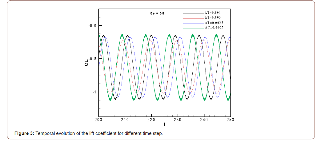
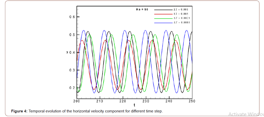
perform all subsequent calculations. To ensure the temporal convergence of results, two Figures 3
and 4 are reported describing the temporal evolution of the lift coefficient
and horizontal velocity components, respectively. From Table 1, it is confirmed that the results of the calculations
with the time step Δt = 0.001 are nearly identical to the results with
Δt = 0.0025 and Δt = 0.0005. That’s why the time step Δt = 0.001 is
applied in all simulations. Table 1:Influence of time step (Δt) at Re = 50. To give more confidence to the results of the current simulations,
some quantitative and qualitative comparisons with other
numerical investigations presented in the literature have been carried
out. The physical problem that is used for the validation of the inhouse
code “NASIM” is the physical model investigated by Breuer
et al. [33]. In the current study, validation of the simulations was carried
out on a non-uniform mesh of dimension m*n =560*340 as the
mesh used by Breuer et al. [33]. The study was conducted over a range of Reynolds number
varying from 10 to 180 and analysis of the effect of this parameter
on the evolution of the Strouhal number and lift and drag coefficients
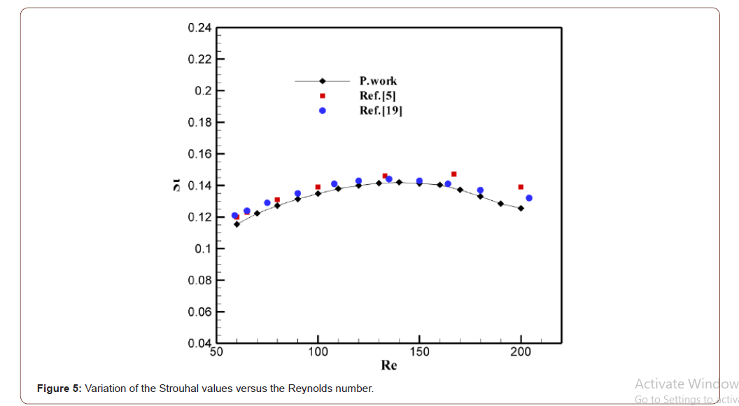
was carried out. Then, the effect of Re on the Strouhal number (Figure 5) was
performed. It is noted that for relatively low Reynolds numbers (50
< Re < 130) the Strouhal number increases with Re values. A significant
change in the structure of flow takes place, namely the movement
of separation point of the trailing edge to the leading edge of
the square cylinder. The Strouhal number is at a maximum at nearly
Re = 140 then decreases again for higher Reynolds numbers. Figure 5 shows that our results are in good agreement with the
results of Breuer et al. [33] and Galleti et al. [34]. As observed, this comparison validates our computer code
making confidence on the presented results. It is noted that validation of the computer code has already
been presented by Fezai et al. [2,14,35-37] which is a contribution
of the current investigation. After validation, attention is now focused to analyze the influence
of the Reynolds number and the change of the triangular
arrangement of the cylinders on the transition from steady to unsteady
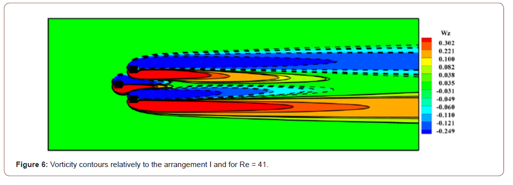
regime due to bifurcation. It can be seen in Figures 6,7 and
8 that there are two recirculating lobes occupying the entire space
of the wake of each arrangement and the flow condition are steady.
This is due to the fact that at such low value of Reynolds number
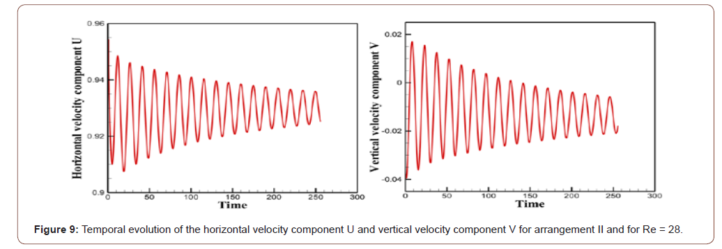
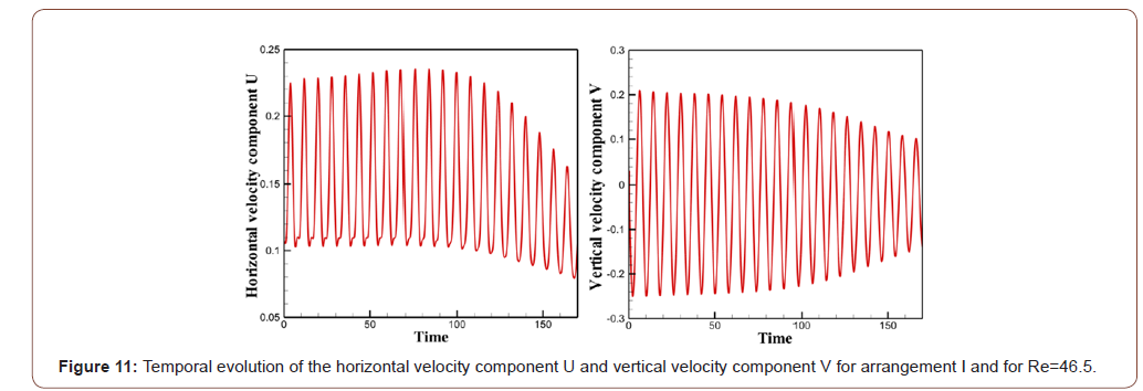
the viscous forces are dominant and resist the movement of flow. The temporal evolution of the horizontal velocity component U
and vertical velocity component V relative to the two arrangements
considered in this investigation are shown in Figures 7 and 9. From
these figures, it can be observed that the amplitude of the oscillations
increases and then, after a certain time, it decreases and tends
towards zero, which means that the stationary flow is stable because
all the disturbances are damped. It is very clear that the type of the triangular arrangement has
ability to change flow behavior for different flow situations. In fact, considering the first arrangement, the steady regime is
observed for Re = 41 while it remains steady up to a Reynolds value
equal to 28 relatively to the second arrangement. It can be deduced
then that the first arrangement tends to stabilize the flow and
strengthen the critical Reynolds value compared to the arrangement
II in which the critical Reynolds number is very close to 28. We can then deduce that the flow remains steady in the range
1≤Re≤41 for the arrangement I. For the cases of the arrangement II,
the flow remains steady in the ranges 1≤ Re ≤ 28. From this observation, it can be clinched that Rec>41 for the
first arrangement and Rec>28 for the 2nd triangular arrangement. As a result, the critical Re value at which the stationary character
disappears depends strongly on the type of triangular arrangement
of the three cylinders. By increasing the Reynolds number, we note that the state of
flow of the two triangular arrangements becomes unsteady and
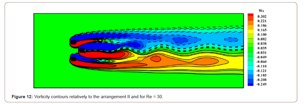
this is well visualized in Figures 10, 11, 12 and 13. It is clear that the
perturbations can no longer be damped because the flow becomes
unsteady and the Reynolds number exceeds the critical value. Figures also shows that the unsteady state of flow occurs at a
Reynolds number very close to 46.5 which means that the transitional
state of flow around the first triangular arrangement remains
in the range 41 We then find that the transition to the unsteady regime begins
in the wake of the second triangular arrangement and then in the
wake of the first arrangement. Therefore, the two triangular arrangements of the three-square
cylinders considered in this investigation result a significant reduction
in the value of the critical Reynolds number. In addition,
these triangular arrangements accelerate the birth and generation
of vortices. Comparing the present results with the one in which the obstacle
is a single square cylinder, we note that there is a big difference
in the flow structure. Again, the flow around a square cylinder remains
stationary up to a fairly high Reynolds number compared to
our results. Indeed, Kelkar and Patankar [6] have focused on the study of instability
that causes a steady laminar flow behind a square cylinder
to result in an unstable laminar flow. They showed that the point of
instability is between Re = 50 and 60 and they computed the value
of the critical Reynolds number having a value Rec=53. In the case of a flow around two square cylinders that are placed
in line with a fixed space ratio g = 3.5 (g= spacing ratio) (Abbasi and
Islam [11]), the unsteady regime appears when the Reynolds number
has a value of 55. Sarwar Abbasi et al. [16] also found that at g = 5 the unsteady
state of flow occurs at Re = 85 which means that the transitional
state of flow around four-inline cylinders remains in the range 68
≤ Re ≤ 84 and the range of Re for transitional flow state in the cases
of two- and three-inline cylinders is 63 ≤ Re ≤ 72 and 68 ≤ Re ≤ 82,
respectively. The Strouhal number St as a function of Re for the two triangular
arrangements considered is shown in Figure 14. It is very
important to mention here that in the present investigation St indicates
the primary vortex shedding frequency, while, itis calculated
by applying fast Fourier transform (FFT) technique on lift coefficients. From Figure 14, it can be observed that St is generated at Re =
50 in the arrangement I. However, in the arrangement II St is generated
at Re = 30. It is important to mention here that the unsteady
regime begins in arrangement II then in arrangement I and this
comes back to the influence of the type of the triangular arrangement
of the three cylinders. It can be seen that the St of the three
cylinders increases monotonically with Re and this is well noted in
the two arrangements (I and II). Furthermore, it exhibits increasing
behavior with increment in the Re values. This is due to the fact
that as Re increases, the shear layers become thin and the strength
of vortices increases, which results in increment in the values of St. It is clear from the figure that the values of the Strouhal number
of the three cylinders in arrangement I are greater than the values
of St of a single square cylinder. Inversely to arrangement I, the St
values of the three cylinders in arrangement II are smaller than the
St values of a single square cylinder. Consequently, we can explain the increase and the decrease
of the values of St which were noted respectively in arrangement
I and arrangement II by the significant influence of the type of the
triangular arrangement of the three cylinders on the mechanism of
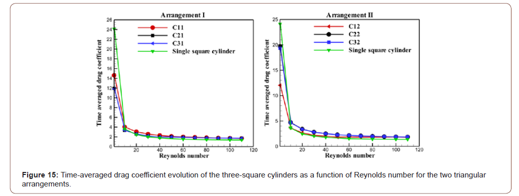
detachment of vortices. We can also be seen in Figure 15 that the values St of the three
cylinders in arrangement I are very close. Also, in arrangement II,
the three cylinders have values very close to St. This indicates that
all the cylinders lose vortices at very close frequencies. According to previous studies [16], the addition of one or more
squares cylinders in the wake of single body significantly affects
the aerodynamic forces. We have also analyzed this phenomenon
in current investigation. The fluctuation of the average drag coefficient for flow around
three square cylinders in two different triangular arrangements
with Re is shown in Figure 16. For small Reynolds numbers, the
average drag coefficient of all cylinders in both triangular arrangements
show decreasing trend with increment in Re. The drag force
induced on cylinders is developed by the pressure and viscous
forces acting on the three cylinders. Therefore, the reason of this
decrease is that as Re increases, the viscous forces become weaker.
Due to this fact, the thickness of shear layers reduces, which results
in weaker drag forces. Also, the average drag coefficient is higher
in steady state of flow than that in transitional and unsteady states
of flow because the CD values in these two states vary very slightly.
In addition, it should be noted that the CD values of the three
cylinders in the two triangular arrangements became almost equal
when 60≤Re≤120. However, the difference between the CD values
appears for the low Reynolds numbers. Interestingly, the present results show that the CD values of the
three cylinders in arrangement I are very low compared to those of
arrangement II. A comparison was made between the mean drag coefficient values
of the three cylinders of each triangular arrangement and the
CD values of an isolated square cylinder (Figure 15), it was found
that the type of triangular arrangement of the three cylinders significantly
changes the fluctuation in drag force. For the low Reynolds numbers (1≤Re≤10), the CD values of
the three cylinders in both arrangements are very low compared
to those of the isolated cylinder. It can be deduced that the two triangular
arrangements of the three cylinders result in a significant
decrease in CD values. When 10≤Re≤50, for arrangement I the CD
values of the two cylinders C21 and C31 are equal to the CD values
of the isolated cylinder, but the CD values of the C11 cylinder are
slightly higher compared to those of the isolated square cylinder.
Inversely to arrangement I, all the CD values of the two cylinders
C22 and C32 of arrangement II are found above the line for that of
the single cylinder when 10≤Re≤50 and the CD curve of the C12
cylinder is found confused with that of the insulated square cylinder.
When 50≤Re≤120, all curves of the average drag coefficient of
the three cylinders in the two triangular arrangements are found
above the line corresponding to the single square cylinder with a
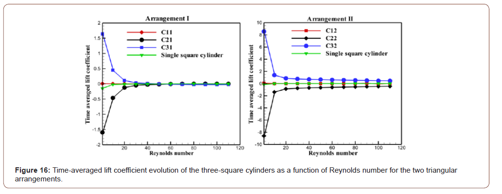
slight difference. When a square cylinder is in cross flow, the lift force is only
generated by vortex shedding caused by the movement of the vortex
from top to bottom and from bottom to top. The dependency
of mean lift coefficient is demonstrated in Figure 16. The single
square cylinder data is also given for comparison. Interestingly, the present results show that the values of the average
lift coefficient of the two cylinders C2 and C3 evolve symmetrically
with respect to the cylinder C1. Therefore, the mean lift coefficient
of cylinder C2 has the identical magnitude but opposite sign
as compared to that of cylinder C3 and this is well noted in the two
triangular arrangements. The average lift coefficients of cylinder C3
are always negative, while those of cylinder C2 are positive, implying
that lift forces on the cylinders are always repulsive. Again, for
Arrangement I, it is found that there is a significant difference for
mean lift coefficients between cylinders C2 and C3 for low Reynolds
numbers because the largest value of CL corresponds to cylinder
C3 for Re = 1 and the most low value of CL corresponds to cylinder
C2 and also when Re = 1. By increasing the Reynolds number, we
notice that the values of CL of cylinder C3 decrease and the values
of CL of cylinder C2 increase. When 40 However, for arrangement II, the curve which corresponds to
the third cylinder C3 increases with the increase in Reynolds numbers,
so this increase is very important for the low Reynolds numbers
(1 Similarly, for large values of the Reynolds number, the curves of
cylinders C2 and C3 evolve symmetrically with respect to the curve
of cylinder C1. This symmetry indicates that the direction of the lift
force applied to the cylinder C2 is opposite to the direction of the lift
force of the cylinder C3. Therefore, this inversely in the direction of
the lift force is due to the arrangement of the three cylinders [37]. In general, the cylinder C32 has a CL greater than the other cylinders
in the two arrangements considered in this study; however,
cylinder C22 has the lowest CL values compared to the other cylinders
in the two triangular arrangements. This might be due to the
strong vortex shedding from the free stream sides. We can see that
the type of triangular arrangement of the three cylinders has a considerable
influence on the fluctuation of the lift force. A numerical investigation was carried out to analyze the influence
of the type of the triangular arrangement of the three square
cylinders on the structure of a two-dimensional flow and on the
aerodynamic forces using a numerical code based on a formulation
of type finite volumes, the projection method and multi-grid acceleration. For this study, Re was varied from 1 to 110. The results were
presented in terms of vorticity contours, temporal evolution of velocity
and temporal histories of drag and lift coefficients. Important findings of this numerical investigation are given below: • The effect of the type of the triangular arrangement of the
three-square cylinders on the birth of the vortex detachment
and on the transitional state from the steady state to the unsteady
state was examined. We then found that the flow remains
steady in the range 1≤Re≤41 for the arrangement I. For
the cases of the arrangement II, the flow remains steady in the
ranges 1≤ Re ≤ 28. Therefore, it can be clinched that Rec>41
for the first arrangement and Rec>28 for the 2nd triangular arrangement.
It is very important to mention that the critical Re
value depends strongly on the type of triangular arrangement
of the three-square cylinders. • The influence of the type of triangular arrangement on the evolution
of the Strouhal number has been analyzed. The values of
the Strouhal number of the three cylinders in arrangement I
have been found to be greater than the values of St in arrangement
II. This comes back to the significant influence of the type
of triangular arrangement of the three cylinders on the detachment
mechanism of the vortices. • The fluctuation of the average drag coefficient for flow around
three square cylinders in two different triangular arrangements
with Re has been analyzed. Therefore, the CD values of
the three cylinders in arrangement I are very low compared
to those of arrangement II. It was found that the type of triangular
arrangement of the three cylinders significantly changes
the fluctuation in drag force. • The purpose of the research is to know the effect of the type of
the triangular arrangement of the three cylinders on the fluctuation
of the lift; we have illustrated the variation of the average
lift coefficient as a function of the Reynolds number. We
have found that the two arrangements considered in this study
considerably affect the fluctuation of the lift force. None. No conflict of interest.Physical Problem

Governing flow equations
Boundary conditions

Numerical Method

Results and Discussions
Time step independence test

Code validation
Influence of the type of triangular arrangement of cylinders
on the bifurcation point from stationary to unsteady
regime






Influence of the type of the triangular arrangement of
three-square cylinders on Strouhal number
Influence of the type of the triangular arrangement of
the three-square cylinders on the drag force
Influence of the type of the triangular arrangement of
the three-square cylinders on the average lift coefficient
Conclusion
Acknowledgement
Conflict of Interest
References
- X Yang, A Zebib (1989) Absolute and convective instability of a cylinder wake. Phys Fluids A 1: 689–696.
- S Fezai, NB Cheikh, B Ben-Beya, T Lili (2016) Obstacle geometry effect on the stability of two-dimensional incompressible flow in a channel. J A F M 9: 625-633.
- S Berrone, V Garbero, M Marro (2011) Numerical simulation of low-Reynolds number flows past rectangular cylinders based on adaptive finite element and finite volume methods. Computers & Fluids 40: 92–112.
- BR Noack, H Eckelmann (1994) A global stability analysis of the steady and periodic cylinder wake. J Fluid Mech 270: 297-330.
- B Gera, Pavan K Sharma, RK Singh (2010) CFD analysis of 2D unsteady flow around a square cylinder. International Journal of Applied Engineering Research, DINDIGUL 1: 602-610.
- KM Kelkar, SV Patankar (1992) Numerical prediction of vortex shedding behind a square cylinder. Int J Numer Meth Fluids 14: 327-341.
- A Lankadasu, S Vengadesan (2008) Onset of vortex shedding in planar shear flow past a square cylinder. Int J Heat and Fluid Flow 29: 1054-1059.
- M Cheng, DS Whyte, J Lou (2007) Numerical simulation of flow around a square cylinder in uniform-shear flow. J fluid struct 23(2): 207–226.
- A Mukhopadhyay, G Biswas, T Sundararajan (1992) Numerical investigation of confined wakes behind a square cylinder in a channel. Int J Numer Meth Fluids 14: 1473- 1484.
- CK Vikram, YTK Gowda, HV Ravindra, CJG Gowda, Manu (2011) Numerical simulation of two-dimensional unsteady flow past two square cylinders. Int J Tech Eng Sys 2(3):355–60.
- WS Abbasi, SU Islam (2018) Transition from steady to unsteady state flow around two inline cylinders under the effect of Reynolds numbers. J Braz Soc Mech Sci Technol 40(168): 1-12.
- P Burattini, A Agrawal (2013) Wake interaction between two side-by-side squares cylinders in channel flow. Comput Fluids 77: 134-142.
- Y Rao, Y Ni, C Liu (2008) Flow effect around two square cylinders arranged side by side using Lattice Boltzmann method. I J M P C 11: 1683-1694.
- E Adeeb, BA Haider, GH Sohn (2018) Flow interference of two side-by-side square cylinders using IB-LBM- effect of corner radius. Results in Physics 10: 256-263.
- J Aboueian, A Sohankar (2017) identification of flow regimes around two staggered squarecylinders by a numerical study. Theoretical and Computational Fluid Dynamics 31: 295–315.
- WS Abbasi, SU Islam, L Faiz, H Rahman (2018) Numerical investigation of transitions in flow states and variation in aerodynamic forces for flow around square cylinders arranged inline, Chinese J Aeronaut 31(11): 2111-2123.
- AA Hetz, MN Dhaubhadel, DP Telionis (1991) Vortex shedding over five in-line cylinders. J Fluids Struct 5(3):243–57.
- R Manzoor, SU Islam, WS Abbasi, S Parveen (2016) Variation of wake patterns and force coefficients of the flow past square bodies aligned inline. Journal of Mechanical Science and Technology 30(4): 1691–704.
- X Liu (2003) Wind loads on multiple cylinders arranged in tandem with effects of turbulence and surface roughness [dissertation]. Baton Rouge: Louisiana State University.
- W Yan, J Wu, S Yang, Y Wang (2016) Numerical investigation on characteristic flow regions for three staggered stationary circular cylinders. Eur J Mech B Fluids 60: 48-61.
- H Rahman, SU Islam, WS Abbasi, G Nazeer (2019) A numerical study for flow around three square cylinders in triangular arrangement. Iranian journal of science and technology, transactions of mechanical engineering.
- S Yang, W Yan, J Wu, C Tu, D Luo (2016) Numerical investigation of vortex suppression regions for three staggered circular cylinders. Eur J Mech B Fluids 55: 207-214.
- Y Bao, Q Wu, D Zhou (2012) Numerical investigation of flow around an inline square cylinder array with different spacing ratios. Computers & Fluids 55: 118–131.
- S Fezai, F Oueslati, NB Cheikh, B Ben-Beya (2019) Prediction of wake structure and aerodynamic characteristics of flow around square cylinders at different arrangements. I J M P C 30(1): 1950015.
- A Sohankar, C Norberg, L Davidson (1998) Low Reynolds number flow around a square cylinder at incidence: Study of blockage, onset of vortex shedding and outlet boundary condition. Int J Numer Meth Fluids 26: 39- 56.
- M Hortmann, M Peric, G Scheuerer (1990) Finite volume multigrid prediction of solutions laminar natural convection: Bench-Mark. Int J Numer Meth Fluids 11: 189-207.
- DL Brown, R Cortez, ML Minion (2001) Accurate projection methods for the incompressible Navier–Stokes equations. Comput Mech 168: 464–499.
- T Hayase, JAC Humphrey, R Greif (1992) A consistently formulated QUICK scheme for fast and stable convergence using finite-volume iterative calculation procedures. J Comput Phys 98: 108-118.
- A Hadjidimos (2000) Successive overrelaxation (SOR) and related methods. J Comp App Math 123: 177-199.
- N Ben Cheikh, B Ben Beya, T Lili (2007) Benchmark solution for time-dependent natural convection flows with an accelerated full-multigrid method. Numer Heat Transfer B 52: 131–151.
- B Ben Beya, T Lili (2008) Three-dimensional incompressible flow in a two-sided non- facing lid-driven cubical cavity. C R Mecanique 336: 863–872.
- M Breuer, J Bernsdorf, T Zeiser, F Durst (2000) Accurate computations of the laminar flow past a square cylinder based on two different methods: lattice-Boltzmann and finite- volume. Int J Heat and Fluid Flow 21: 186-196.
- B Galletti, CH Bruneau, L Zannetti, A Iollo (2004) Low-order modelling of laminar flow regimes past a confined square cylinder. J Fluid Mech 503: 161–170.
- S Fezai, N Ben-Cheikh, B Ben-Beya, T Lili (2019) Numerical study of obstacle geometry effect on the vortex shedding suppression and aerodynamic characteristics. International Journal of Numerical Methods for Heat & Fluid Flow 30(2): 469-495.
- S Fezai, F Oueslati, NB Cheikh, B Ben-Beya (2018) Sensitivity of wake parameters to diameter changes for a circular cylinder. I J M P C 29(6).
- S Fezai, NB Cheikh, B Ben-Beya, T Lili (2017) Numerical study of Vortex shedding suppression and aerodynamic characteristics of three obstacle configurations having two shapes. J Braz Soc Mech Sci Technol 39(7): 2519-2534.
- S Zheng, W Zhang, X Lv (2016) Numerical simulation of cross-flow around three equal diameter cylinders in an equilateral-triangular configuration at low Reynolds numbers. Comput fluids 130: 94-108.
-
Salwa FEZAI, Racha NEFZI, Brahim BEN-BEYA. Analysis of the Interaction in Flow Around Three Staggered Square Cylinders at Two Different Triangular Arrangements. Glob J Eng Sci. 7(1): 2021. GJES.MS.ID.000651.
-
Flight safety, Risk assessment, Remotely piloted unmanned aircraft, Safety management, Automation
-

This work is licensed under a Creative Commons Attribution-NonCommercial 4.0 International License.


