 Research Article
Design, Construction and Performance Comparison of Fuzzy Logic Controller and PID Controller for Two-Wheel Balance Robot
Mehrdad Esmaeilipour1* and Mohammad Hossein Zalzar2
1Department of Electrical, Islamic Azad University, Bushehr Branch, Bushehr, Iran
2Department of Electrical, University of Persian Gulf, Bushehr, Iran
Mehrdad Esmaeilipour, Department of Electrical, Islamic Azad University, Bushehr Branch, Bushehr, Iran.
Received Date:January 29, 2025; Published Date:February 05, 2025
Abstract
In this article, the design, construction and control of a two-wheeled balancing robot was carried out with two PID controllers and fuzzy logic. This type of robot has advantages such as lower energy consumption and the ability to be used in small spaces with the ability to navigate in the entire workspace and rotate in place compared to other wheeled robots. Therefore, the need for research on the knowledge of building a twowheeled balancing robot and controlling its balance optimally is felt to enter fields such as medical robots (assistant and military and robotics of humanoid robots), etc. For the design and modeling of the robot, SolidWorks software was used, and for programming, Arduino software was used along with the Arduino microcontroller board. In this research, the robot system is nonlinear and is considered as a black box, and two linear PID and nonlinear fuzzy controllers have been used. After conducting investigations and obtaining numerous results for both controllers in the results section, the performance of the fuzzy controller was observed to be much more optimal than the PID controller. The PID coefficients have been obtained experimentally, and the membership functions of the fuzzy controller have also been adjusted experimentally, and the Mamdani method and trapezoidal functions have been used. All the results have been obtained from the Arduino software and with a serial port connection between the computer and the Arduino microcontroller, all of which are presented in the results section.
Keywords:Fuzzy controller; PID controller; Two-wheeled balance robot
Introduction
Modern control is based on the time domain analysis of differential equation systems. Modern control has simplified system design because this theory works based on a model of the real control system. However, the stability of the system is sensitive to the model error, that is, when the controller designed based on the model is applied to the real system, the system may not be stable. In order to prevent such a situation from occurring, the range of possible errors is first determined during design, and then the control system is designed so that it remains stable if the error is within this range. The design method based on this principle is called robust control. Both frequency response and time domain approaches are used in this theory, and this theory has a lot of mathematical complexity [1].
Two-wheeled balancing robots that act like inverted pendulums are naturally unbalanced, nonlinear, and loaded [2] and consist of two moving wheels, each located on one side of its body and driven by direct current actuators. As a model of an inverted pendulum, the robot’s balance is achieved by controlling the rotation of its wheels. Since the introduction of the two-wheeled balancing robot [3], this type of robot has attracted great interest due to its many application opportunities in the field of design, controller, and signal processing of distributed control systems. Simple design and use in tight spaces, resulting in a small footprint, are also other reasons for the popularity of this type of robot. However, the inherent tendency of the robot to be unbalanced indicates the need for dynamic control of the system.
Even with a higher height, they can accelerate quickly without falling over. On the other hand, not having more than two wheels means that they can use larger wheels to cross uneven surfaces [4]. Given the characteristics and features mentioned, this type of robot is used in fields such as agriculture, transportation, etc. [5, 6]. Also, due to its self-control, flexibility, and small size, this type of robot has high usability in dangerous and small workspaces [7]. In some studies, they are used for educational purposes [8].
The study of two-wheeled balancing robots emphasizes more on the robot balance control technology. The first researcher in this field is Professor Yamafuji, who works at the University of Electrical Communications in Japan. In 1987, he was working on an invention called a (parallel) two-wheeled robot that incorporated two-wheeled robot technology [9]. Soon after, Sony Electric developed a twowheeled self-balancing robot called the Feelsro and demonstrated it at the June 2002 Robot World Cup. The world’s first humanoid two-wheeled self-balancing robot was developed by ATR Research Laboratory in Japan. Any instability and instantaneous movement of the robot’s upper body must be compensated immediately and the balance maintained [10]. Various techniques have been proposed for controlling two-wheeled robots, which require a good understanding of the mathematical model, which is represented by Lagrange’s equations [3, 11, 12], Newton-Euler equations [13], Gibbs-Eppel equations of motion [14, 15], or the Ken method [10].
In general, such a device is affected by external disturbances. Also, the lack of a dynamic model, errors in parameter estimation, and noise related to the measurement of input parameters through sensors are other influencing factors that need to be considered [16]. To In order to effectively control the two-wheeled balancing robot, linear and nonlinear control strategies have been used. Among the linear controllers, PID controller [11, 12, 17-19], LQR [13] and LQG [15] have been used. These linear controllers offer a limited range of performance due to linear processing, thus limiting the performance of the robot. As a result, the use of nonlinear controller techniques can overcome these limitations. In a study conducted by Slavo et al. in 2014 on the control of two-wheeled balancing robot with LQR controller. One of the reasons cited for using the controller is the lack of an accurate mathematical model for the robot [20].
Zhang, et al. [20] proposes a fuzzy fractional-order PID (FFOPID) controller for the motion control of a TWSBR system in an inclined environment. The control goal of TWSBR is to realize the wheel position control and to stabilize the non-vertical direction of intermediate body (IB). Finally, we compare the control effect of the proposed FFOPID controller with that of the integer-order PID controller, the fuzzy PID (FPID) controller, and the fractional-order PID (FOPID) controller when TWSBR moving on the inclined plane. The simulation results show that the FFOPID controller has better control performance and anti-interference ability.
Mudeng, et al. [21] apply a Proportional Integral Derivative (PID) controller as a control system in a self-balancing robot with a working principle is similar to an inverted pendulum. An Inertial Measurement Unit (IMU) sensor is utilized to detect the angular acceleration and angular velocity of the self-balancing robot. The phase design is constructed by planning the robot dimension, mechanical system, and an electronic system. Particularly, this study performs mathematical modeling of the robot system to obtain the transfer function. In addition, we simulate the PID parameter with multiplication between the basic parameter and several fixed constants. The simulation results indicate that the robot can maintain its balance and remains perpendicularly stable for balancing itself.
Kumar, et al. [22] investigates a novel coupling-based mixed interval type-2 fuzzy logic controller (MIT2FLC) for trajectory tracking problems of highly nonlinear and complex robot manipulator plants. For checking the performance, the MIT2FLC approach is compared with its type-1 fuzzy counterparts, namely mixed type-1 fuzzy logic controller (MT1FLC), type-1 fuzzy logic controller (T1FLC) and PID controllers. Robustness analysis of the proposed controller is investigated for external disturbances, varying system parameters, and random noise.
Robot Design
In this section, items such as design and selection, structure dimensions and materials used in the construction of the robot are described in detail.
Selecting the appropriate design
The first step in designing a balancing robot is to select the appropriate structure according to the purpose of its controller. For this purpose, in this research, a platform-type two-wheeled balancing robot has been built in order to apply controllers and study the efficiency of each of them on the balance of the robot. The prototype was designed in the 3D design engineering software SolidWorks 45. The remaining steps, including the selection of electronic parts, construction materials, construction methods, etc., are described step by step.
Robot Dimensions
Since the robot was built solely to study control methods, an attempt was made to design a robot with small dimensions and, as a result, low cost, so that the robot operators have the ability to apply appropriate torque to maintain the balance of the robot. This robot was designed with a simple floor plan to place the robot’s electronic components, so that the dimensions and spacing of the floors and the selection of components for each floor were carried out taking into account the principle that the center of mass of the robot should be in its upper part and the aim is to control the imbalance of the two-wheeled robot.
Robot Shape
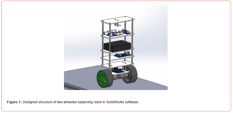
In order to achieve optimal performance of the robot, a solid and symmetrical framework has been used in its structural design in SolidWorks software. This platform has the ability to increase floors and place various sensors and electronic components, as well as cameras for image processing. Therefore, this robot will have the ability to increase capabilities in all fields, including automatic navigation and recognition of the surrounding environment, which in this research is only concerned with controlling the balance of the robot. The final model of the two-wheeled balancing robot that was carried out in SolidWorks software is shown in Figure 1.
Material selection
Based on the ability to cut with a laser cutting machine and easy drilling to place robot parts, Plexiglass 46 material was used to make it. The advantages of this material include low density, good resistance to thickness, and accurate cutting based on the output map from SolidWorks software for use in two-wheeled balancing robot.
Selecting electronic and mechanical parts of the robot
To build a high-performance robot, selecting the right parts that have the best performance in a set is one of the most important parts of building a robot. The selection of electronic and mechanical parts of the robot should be based on the defined performance for that part, and if the performance is similar, the best part can be selected based on their strengths and weaknesses. Ultimately, excellent choices can create a high-performance robot. Of course, cost is also an important factor in selecting parts because a cheap part can partially meet the performance of an expensive part.
Selecting the type of actuator
In selecting the right actuator for the two-wheeled balance robot, DC motors with a gear box and a Hall effect encoder have been used to build the robot. High-speed DC motors, if used with a gearbox, provide high torque with a small volume to the robot. High torque with high reaction speed is needed by two-wheeled balancing robots to maintain their balance. On the other hand, to adjust the speed and find out the speed of the tires and calculate the linear speed of the robot, it is necessary to use an encoder on the output shaft axis of the robot so that the robot can move at the desired speed. The initial position and distance traveled can also be one of the encoder outputs, which in this research we only need to maintain balance and the distance, speed and initial position are not design considerations. So, the geared high-speed DC motor is the best option to be in the built robot set, but to continue the research and practical development of the robot, geared DC motors with Hall effect encoders have been used to build the robot.
Construction
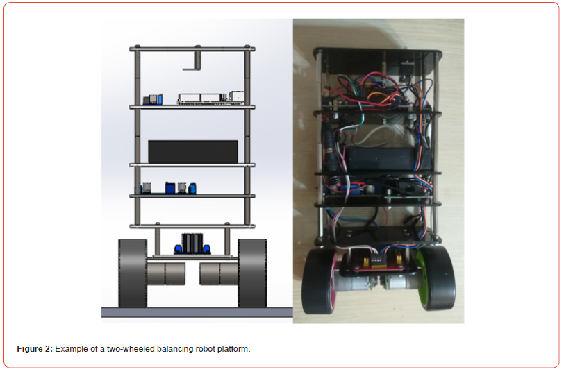
After designing the three-dimensional model of the twowheeled balancing robot and also choosing the material, we used plexiglass material here for ease of cutting and complete compliance with the output design from the design software. To make the platform prototype, various parts of the robot are cut. Due to the choice of plexiglass, the need for high precision in cutting parts, and the elimination of machining operations, laser cutting has been used in cutting various parts of the robot. The laser cutting machine is very important in carrying out specific cutting orders because this machine is used with the most up-to-date systems for laser operations. Laser cutting machines are among the most popular machines and are used in most cases for precise cutting. After cutting the parts and assembling them all with electronic and mechanical parts such as tires and robot shafts, the finally built model is shown in Figure 2, which are displayed side by side to match the output design from the design software.
Control
Two control methods have been used to control the balance of the two-wheeled robot to compare the efficiency of these methods in controlling the robot and the results obtained show which method shows the desired performance in which conditions.
The methods used are one PID method assuming the linearity of
the problem and the other fuzzy logic considering the nonlinearity of
the problem. The principles that we have considered in controlling
the robot are as follows:
• The two-wheeled balancing robot system is considered as
a black box without considering the equations governing the
balance of the robot.
• The surface intended for robot navigation is an uneven surface.
• Obtaining PID coefficients and the range of input and output
values in fuzzy logic has been done experimentally
• The method used in fuzzy logic is Mamdani method
PID controller
In this method, considering the availability of the built platform of the two-wheeled balancing robot, we obtained PID values by trial and error, then by entering the impact type input, we plotted the robot’s balance graph with the output data from the MPU 6050 sensor and communicating with the computer via the serial port in the Arduino software. The steps for obtaining the optimal PID coefficients experimentally are as follows: first, we started with the proportional coefficient (P), as we know, the effect of this coefficient is that it increases the speed of the system and reduces the steadystate error to some extent, but does not make it zero. We know that to maintain the balance of the built two-wheeled balancing robot, the error must tend to zero, so the speed coefficient P alone will not be effective and other coefficients will need to be adjusted. Using a large coefficient. It increases the tendency to maintain balance, so the torque applied by the motors for even a small impact will be large and at high speed to create imbalance in the robot, and this in itself is a factor in creating imbalance in the robot.
The integral coefficient or I also makes the steady-state error zero, but it adds a large amount of unwanted oscillations to the transient response, and this in turn causes imbalance in the robot itself in situ. The derivative coefficient also weakens the oscillations of the transient response, so in addition to using the integral coefficient, we will need to use the derivative coefficient.
Fuzzy controller
The Mamdani method has been used to implement the fuzzy logic controller. In this method, according to Figures 3 to 5, the membership functions must be defined at first. We have considered two inputs as inputs for fuzzy control; One is the angle value at any moment and the other is the change in angle at any moment, which Figure 3 shows three membership functions, and one is the negative angle (ND) which is a trapezoidal membership function from negative infinity to -2, and the other is the angle near zero (ZD) which is again defined as a trapezoidal function from 5 to -5. There is a range between these two functions, and if the angle is in that part, that is, between -5 and -2, depending on the membership level, from a value between zero and one, it may be 0.7 of a negative angle and 0.3 of a zero angle, which is the same logic as the logic of human reasoning, and uncertainty is involved here, and its difference from zero and one or binary logic is evident here. The membership function of the positive angle (PD) is also considered from zero to infinity. In fact, for the angle input at any moment, we have considered three membership functions that are overlapping functions. The more or less the overlap, the different results of the fuzzy logic. This case, Figure 3, provides the best result for the defined fuzzy logic controller through trial and error for the first input.
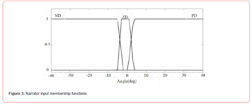
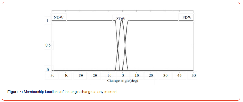
Figure 4 show the amount of angle change at any moment, which is measured by the MPU 6050 sensor in a fraction of a second and with the smallest angle change and is used by the fuzzy logic controller. Here, the size of the upper side of the trapezoid is considered to be much smaller, which means that with this small value, the robot does not show any reaction. If this value is taken large, the robot oscillations will be greater.
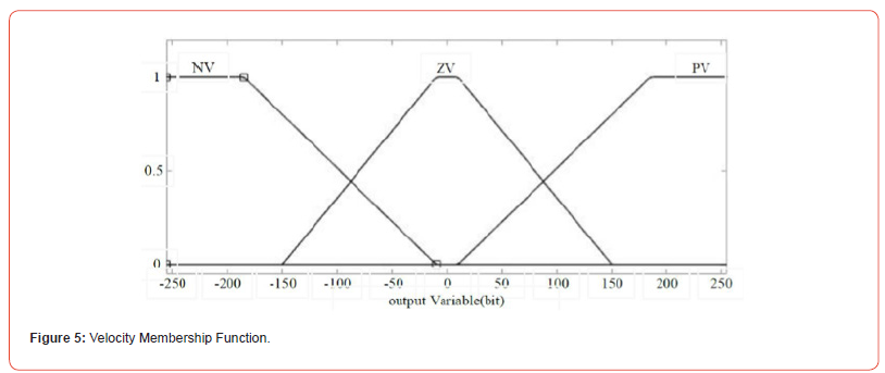
Figure 5 shows the output membership functions to be applied to the actuators. These functions are trapezoidal in type and the values of the horizontal axis indicate the output of the fuzzy logic controller due to the reasoning that is written from the rules. These values are the same values that must be sent to the actuator driver so that the drivers can send the required speed and torque to the actuators with the PWM wave and the robot can maintain its balance. It is worth mentioning that the program written for the MPU 6050 sensor uses the I2C interface and is taken by the Kalman filter of the sensor noise and calculations are performed at high speed so that the robot can react quickly. Here, three membership functions are defined: the first is negative speed, which means the direction of the speed is counterclockwise, and the second is zero speed, which if we look carefully is considered to be completely zero in a very small range, and in the rest of the zero-speed membership function, the membership rate is raised. For positive speed, the function is again trapezoidal and its overlap with the zero-speed membership function is symmetrical with the overlap of the negative speed membership function and the zero function.
Results
In this section, the performance comparison of two PID controllers and fuzzy logic is used for the robot that was built. This robot, as described in the details of the construction in the third chapter, has the ability to apply two controllers through the Arduino software on the Arduino microcontroller. To adjust the coefficients and values of the controllers manually and experimentally, by trial and error and observing the equilibrium output diagram of the angle-type robot, we tried.
Results of the PID controller
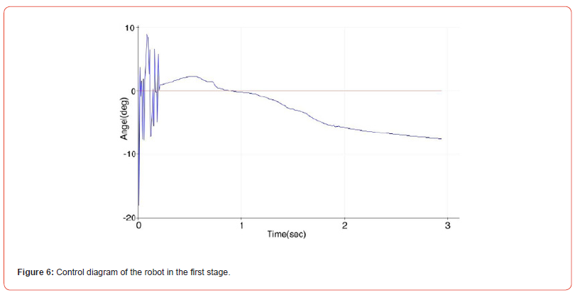
In the first stage, we use only the P coefficient for the PID controller and the rest of the coefficients are given zero, which is completely related to the physics of the system and we obtain the coefficients empirically and we have no problem with the complexity of physics.
Figure 6 shows the fact that the robot actually falls and using the P coefficient alone cannot control the balance of the robot.
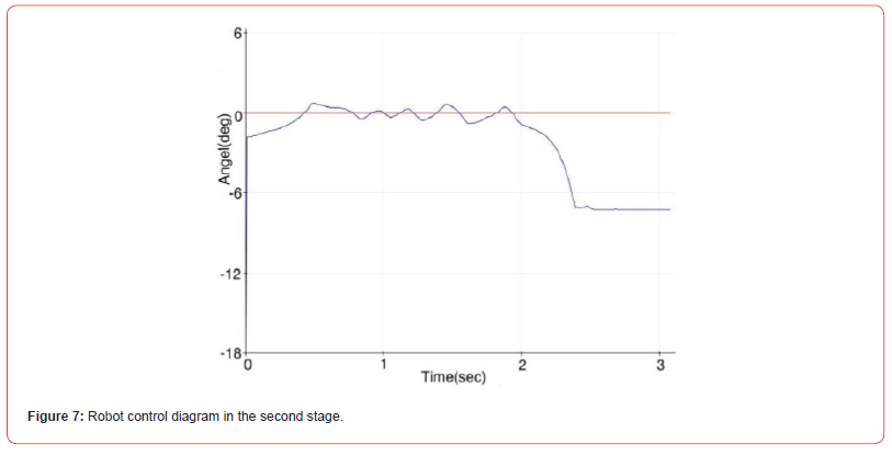
In the second stage, by increasing the proportional coefficient, we tried to test the balance response of the robot with respect to the value of this coefficient, the result of which is plotted in Figure 7.
In Figure 7, it can be seen that the presence of the P coefficient without other coefficients and simply increasing the P coefficient value to 100 causes the robot to oscillate sharply and fall. Although it has an initial balance of up to 2 seconds, we eventually have the robot fall.
Considering that in the controller, the proportionality of the P coefficient alone causes a large error and, as a result, a large signal to the input, therefore, in Figure 7, an equilibrium is initially created, which, as the error increases or the difference between the angle value and the angle, a large signal reference is created and applied to the wheels, and therefore the robot falls.
Therefore, we must also use other coefficients, and for now, we will suffice with this 2-second equilibrium for the P coefficient value and observe the effect of other coefficients on the robot balance control.
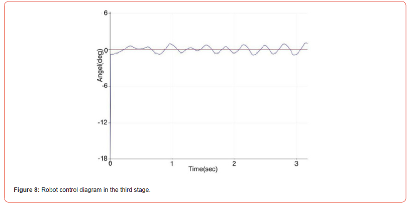
In the third step, we use the integrator coefficient or I with a value of 60 for the controller and set the coefficient value to 100 and the derivative coefficient or D to zero to measure the effect of the integrator coefficient along with the proportional coefficient on the output graph of the MPU 6050 sensor.
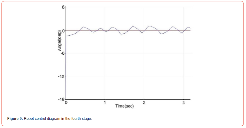
Figure 8 shows the robot’s strong oscillation again around the balance point and the possibility of the robot falling with the slightest impact. In this stage, along with the proportional coefficient, the integral coefficient was also used. The desired result, which is the robot’s balance around the zero point, was not observed and severe oscillations were applied to the robot and the controller could not maintain the robot’s balance. In the fourth stage, we use the value 100 for the proportional coefficient and 400 for the integral coefficient. Figure 9 shows the robot’s balance diagram around the balance point. It is true that the integral coefficient creates the robot’s balance around the robot’s balance point with a permanent oscillation, but in a two-wheeled robot, the goal of balance is to settle down and the robot’s balance angle tends to zero, which is not possible with the proportional-integral coefficient according to the results obtained.
In this stage, by adding a derivative coefficient to the proportional-integral controller, we seek to reduce the robot’s oscillations and the robot’s ability to respond to impact input to maintain balance.
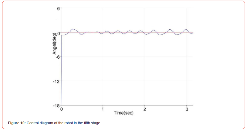
For fast response and large torque against impact, we increased the proportional coefficient to 120 and used the same integral coefficient of 400 so that oscillations do not increase, and we applied a derivative coefficient of 1. The equilibrium diagram in Figure 10 is drawn for the robot with these control values, which shows the reduction of oscillations and the robot’s tendency to maintain balance.
In the sixth stage, by only increasing the derivative coefficient to 3.5 and keeping the other values constant, we see in Figure 11 that the robot has found a smaller amplitude of oscillations around the equilibrium point. But it still has not found complete equilibrium around the equilibrium point, meaning it has oscillations in place. We used all the coefficients in the stage, but we still need to modify and change the coefficient whose high value can cause the robot to oscillate.
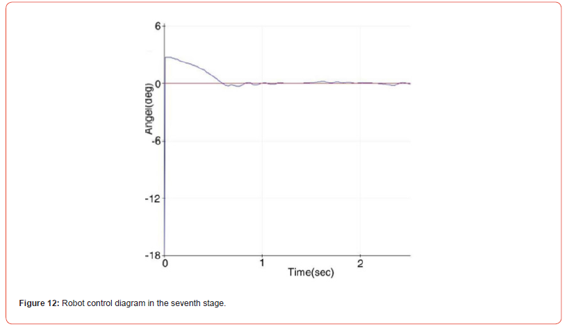
In the last stage, by reducing the value of the integral coefficient to 3.5, the amplitude of oscillations is greatly reduced and according to Figure 12, the robot even reaches equilibrium. At this stage, the remaining coefficients have the same value as before.
Using the trial-and-error method and repeated iterations, we finally reached a desirable result for the PID coefficients, the results of which can be seen in Figure 13, and brought better stability and stability to the two-wheeled balancing robot.
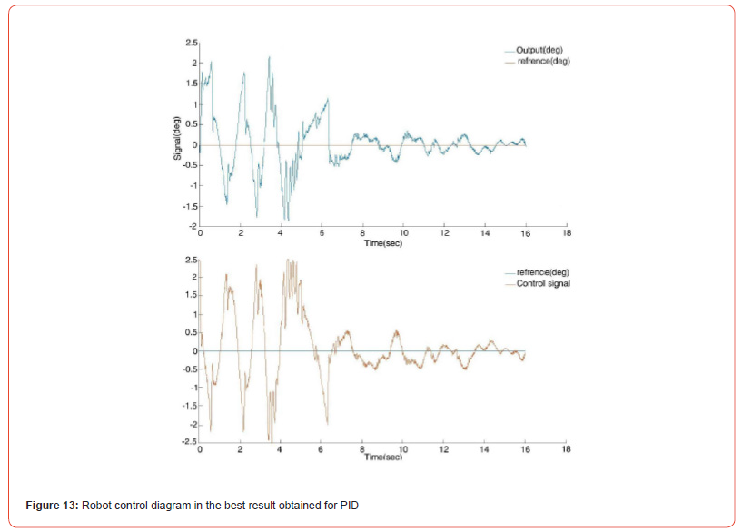
In Figure 13, the output is the final output and the balance angle of the robot, and the reference diagram is the balance line. The control signal is the PWM signal sent from the Arduino microcontroller to the motors. As can be seen, the control signal is in the opposite direction of the control signal at any moment, and this process will continue until equilibrium is reached.
Figure 14 shows the reaction of two-wheeled balancing robot to impact with PID controller and the coefficients obtained in Figure 13. As can be seen from the diagram, by applying impact to the robot, the robot takes about 12 seconds to reach equilibrium, but it does not overturn and regains its balance due to the movement and torque of the motors opposite the angle of the robot.
According to the output diagrams from the MPU 6050 sensor of the robot with PID controller, the result obtained is that we need all three coefficients to control the robot, and all three coefficients must be obtained by trial and error or by other methods that can optimize the PID coefficients. The experimental method is a very tedious method and may not achieve the desired result, and it is better to use the PID method together with other methods. On the other hand, the type of motors used, the gearbox backlash, and the design of the structure can be other factors that complicate the control of the robot. On the other hand, this method is not resistant to impacts and uneven surfaces, despite not reducing the control error to below one degree, but it has the ability to control and respond quickly to impacts.
Result of the fuzzy controller
By applying a fuzzy logic controller that has a nonlinear nature, we have tried to compare the results of the linear PID controller with the nonlinear fuzzy controller. In this controller, we used the Mamdani method with trapezoidal functions and obtained the values of the functions by trial and error according to the PID controller. Here, we have presented the graph of the best results for the fuzzy controller.
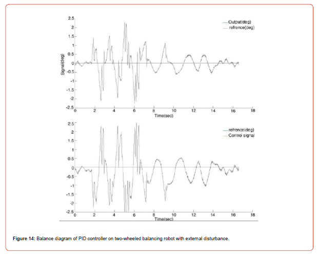
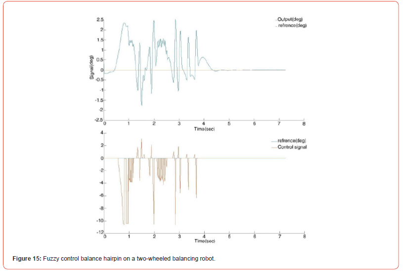
Figure 15 is the result of the fuzzy control on the balance of the two-wheeled balance robot. As can be seen, the robot reached equilibrium within two seconds. This controller, with its nonlinear nature, has been able to balance the nonlinear system of the twowheeled balance robot well.
Figure 15 is the initial balance of a two-wheeled balancing robot on which the fuzzy control algorithm has been applied.
Comparison of results
In the research, we want to make a comparison regarding the performance of two PID and fuzzy controllers applied to the robot because two controllers on the robot cannot perform the control action at the same time.
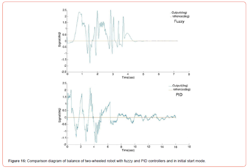
In Figure 16, we have brought both balance diagrams of the robot from Figures 13 and 14 together so that the comparison can be done easily and accurately and the result of the comparison between the two fuzzy and PID controllers can be easily seen. Therefore, it can be seen that although the PID controller has been able to maintain the balance of the robot, this balance is not complete and sometimes the robot goes out of balance and the robot is oscillating and vibrating around the balance angle and even compared to the fuzzy controller whose result is shown in Figure 14, it has not reached balance quickly. This is because the fuzzy controller reaches equilibrium much faster and stands completely still and without oscillation at the equilibrium point. This is because the fuzzy controller uses human logic (but) and (if) in the control discussion and has inherent flexibility in controlling nonlinear systems.
Conclusion
The two-wheeled balancing robot system is such that it is involved in many factors to achieve the balance of the robot, including the unevenness of the surface below, the tilt of the robot, the friction surface between the wheels and the surface below the wheels. All of these factors cause a mismatch between the output and input applied to the wheels (the same torque applied by the motors. Therefore, despite the nonlinear nature of the system in this study, we have considered the system in a linear range. However, due to the nonlinear nature of the two-wheeled balancing robot system, as can be seen, the fuzzy logic controller shows much better performance than the PID controller in the results section and the balance of the robot is maintained without oscillation. On the other hand, the adjustment of values in the fuzzy controller is done much faster than the PID controller in this study, and this is one of the other advantages of the controller. It is fuzzy. The fuzzy controller, with its nature of being close to human logic, shows high flexibility in behavior and decision-making, just as humans are very successful in maintaining their balance when walking, standing, or receiving an impact, etc. Because it does not operate in a zero-one logic in decision-making and has a logic similar to fuzzy logic, in fact, fuzzy logic reflects the logic of human behavior when making decisions, and this research shows this issue well by comparing the results that only three fixed coefficients in PID have less ability than fuzzy logic in controlling the balance of a two-wheeled robot.
A two-wheeled balancing robot uses less energy than other wheeled robots and has advantages such as high maneuverability in a small space due to rotation, the ability to increase capabilities such as recognizing the surrounding environment and other unique capabilities. The need for study in the field of balance control is still felt. Therefore, this research focuses more on the balance of the robot, and the research results show that the balance of the robot can be well maintained by applying optimal controllers.
These types of robots can function as humanoid robots by upgrading the robot structure and adding processing and images to identify the surrounding environment and various sensors and sound recognition algorithms, and can be used as assistants for the disabled, or by changing the shape of the tires and using powerful actuators, they can also be used in uneven environments. One way to increase the ability to maintain balance in two-wheeled robots is to use learning algorithms along with a controller to increase the flexibility of the robot and the ability of the robot to encounter balance-disrupting factors each time.
Data Availability Statement
The data that support the findings of this study are available on request from the corresponding author.
Funding Statement
This research did not receive any specific grant from funding agencies in the public, commercial, or not-for-profit sectors.
Conflict of Interest Disclosure
The authors declare that they have no conflict of interest.
Ethics Approval Statement
Not applicable.
Patient Consent Statement
Not applicable.
Permission to Reproduce Material from Other Sources
Not applicable.
Clinical Trial Registration
Not applicable.
References
- Ogata K, Yang Y (2002) Modern control engineering. Vol. 4. Prentice hall India
- Bature AA, Buyamin S, Ahmad MN, Muhammad M (2014) A comparison of controllers for balancing two wheeled inverted pendulum robot. International Journal of Mechanical & Mechatronics Engineering 14(3): 62-68
- Grasser F, D'Arrigo A, Colombi S, Rufer AC (2002) JOE: a mobile, inverted pendulum. IEEE Transactions on Industrial Electronics 49(1): 107-114
- Chan RPM, Stol KA, Halkyard CR (2013) Review of modelling and control of two-wheeled robots. Annual Reviews in Control 37(1): 89-103
- Azimi MM, Koofigar HR (2013) Model predictive control for a two wheeled self balancing robot. In: Robotics and Mechatronics (ICRoM), 2013 First RSI/ISM International Conference on, IEEE.
- Brisilla R, Sankaranarayanan V (2015) Nonlinear control of mobile inverted pendulum. Robotics and Autonomous Systems 70:145-155
- Sun L, Gan J (2010) Researching of two-wheeled self-balancing robot base on LQR combined with PID. In: Intelligent Systems and Applications (ISA), 2010 2nd International Workshop on, IEEE
- Solis J, Nakadate R, Yoshimura Y, et al (2009) Development of the two-wheeled inverted pendulum type mobile robot WV-2R for educational purposes. In: Intelligent Robots and Systems, IEEE/RSJ International Conference on, IEEE
- Yamafuji W, Kawamura R (1989) Attitude control of coaxial two-wheeled car [J]. Journal of Robots 17(4): 74-79
- Kamida S (2002) Evaluation of self-discipline robot interacting with human [J]. Journal of Robots 20(3): 1-9
- Jamil O, Jamil M, Ayaz Y, Khubab Ahmad K (2014) Modeling, control of a two-wheeled self-balancing robot. In: Robotics and Emerging Allied Technologies in Engineering (iCREATE), 2014 International Conference on, IEEE
- Peng K, Ruan X, Zuo G (2012) Dynamic model and balancing control for two-wheeled self-balancing mobile robot on the slopes. In: Intelligent Control and Automation (WCICA), 2012 10th World Congress on, IEEE.
- Akesson J, Blomdell A, Braun R (2006) Design and control of yaip—An inverted pendulum on two wheels robot. In: Computer Aided Control System Design, 2006 IEEE International Conference on Control Applications, 2006 IEEE International Symposium on Intelligent Control, 2006 IEEE, IEEE
- Sun F, Yu Z, Yang H (2014) A design for two-wheeled self-balancing robot based on Kalman filter and LQR. In: Mechatronics and Control (ICMC), 2014 International Conference on, IEEE
- Raffo GV, Ortega MG, Madero V, Rubio FR (2015) Two-wheeled self-balanced pendulum workspace improvement via underactuated robust nonlinear control. Control Engineering Practice 44: 231-242
- Grasser F, D'Arrigo A, Colombi S, Rufer A (2002) JOE: a mobile, inverted pendulum. IEEE Transactions on Industrial Electronics 49(1): 107-114
- Ren T-J, Chen T-C, Chen C-JJCEP (2008) Motion control for a two-wheeled vehicle using a self-tuning PID controller. Control Engineering Practice 16(3): 365-375
- Xu C, Li M, Pan F (2011) The system design and LQR control of a two-wheels self-balancing mobile robot. In: Electrical and Control Engineering (ICECE), 2011 International Conference on, IEEE
- Slavov T, Kralev J, Petkov PJCAS (2014) Linear-Quadratic Control of a Two-Wheeled Robot. Comptes rendus de l’Acade'mie bulgare des Sciences 67(8): 1153-1158
- Zhang J, Zhao T, Guo B, Dian S (2021) Fuzzy fractional-order PID control for two-wheeled self-balancing robots on inclined road surface. Systems Science & Amp; Control Engineering 10(1): 289-299.
- Mudeng V, Hassanah B, Priyanto YT, Saputra O (2020) Design and Simulation of Two-Wheeled Balancing Mobile Robot with PID Controller. International Journal of Sustainable Transportation Technology 3(1): 12-19.
- Kumar A, Raj R, Kumar A, Verma B (2023) Design of a novel mixed interval type-2 fuzzy logic controller for 2-DOF robot manipulator with payload. Engineering Applications of Artificial Intelligence 123.
-
Mehrdad Esmaeilipour* and Mohammad Hossein Zalzar. Design, Construction and Performance Comparison of Fuzzy Logic Controller and PID Controller for Two-Wheel Balance Robot. Glob J Eng Sci. 11(5): 2025. GJES.MS.ID.000773.
-
Fuzzy logic controller, Humanoid robots, Real control system, Mechanical system, Electronic system, Physics, Sensor, Microcontroller, Algorithms
-

This work is licensed under a Creative Commons Attribution-NonCommercial 4.0 International License.


