 Research Article
Compression Capacity of Long, Thin-Walled Steel- Tube/Bamboo-Plywood Composite Hollow Columns with Binding-Bars
Weifeng Zhao1* and Jiguang Zhou2
1Guangdong Construction Polytechnic, Guangzhou, 510440, China
2Zhuhai Construction Engineering Hoiding Group CO., LTD, Zhuhai, 519000, China
Weifeng Zhao, Guangdong Construction Polytechnic, Guangzhou, 510440, China.
Received Date:June 24, 2024; Published Date:June 28, 2024
Abstract
A new type of thin-walled steel tube/bamboo plywood composite hollow column with binding bars (SBCCB) that used transverse binding bars to reinforce the composite column was developed. The compression performance of 4 specimens with larger slenderness ratio was tested to examine the failure mode of the SBCCBs. Finite element numerical simulations were performed to extend the influential factor analysis based on the test results, and the influences of the slenderness ratio, the net cross-sectional area of the bamboo plywood, the relative spacing ratio and row number of the binding bars on the ultimate bearing capacity were analyzed. The results indicated that the SBCCB compression failure modes were mainly crushing failure of the bamboo plywood material, partial debonding failure of the adhesion interface and buckling instability failure; the ultimate bearing capacity of the SBCCBs was not only related to net cross-sectional area and slenderness ratio, but also greatly affected due to binding bars. Transverse binding bars were used to ensure the integrity of the composite column, to effectively reduce the debonding failure of the adhesion interface, to change the limiting damage mode, and to significantly improve the load-bearing capacity of the SBCCBs.
Keywords:Bamboo-plywood; Thin-walled steel-tube; Composite column; Axial compression; Bearing capacity
Introduction
Bamboo-laminated composite engineering materials are one of the most feasible applications for utilizing bamboo resources [1,2]. However, applications of bamboo-laminated materials in engineering have focused on concrete-based construction; research on using bamboo-laminated materials as an engineered structural material has only been conducted recently [2-4]. Professor Xiao [5] proposed that bamboo has not been widely used in modern engineering structures primarily because of the lack of effective theoretical validation from solid mechanics, materials science, structural design, and experimental technology. In recent years, significant progress has been made in the studies and applications of bamboo composite materials and bamboo-laminated materials [6-12], including steel/bamboo plywood composite structural columns [9,13-16]. With the increasing shortage of engineered wood and the promotion of sustainable green construction materials, research into steel/bamboo composites has received significant attention worldwide. Liu et al. [13] developed a steel/ bamboo (curtain plywood) box composite column, and Li et al. [4] explored a bamboo composite column reinforced by steel rebars.
Xie et al. [14] explored a similar column application with coldformed thin-walled C-section steel and a bamboo-wood composite plate. Zhao et al. [15,16] developed a thin-walled steel tube/ bamboo plywood hollow composite column. The thin-walled steel tube in the column served as the skeleton, making the composite suitable for industrial assembly. The thin-walled steel tube also increased the cross-sectional area of the composite columns, thereby reducing the slenderness ratio and effectively improving the instability and failure performance of the columns under pressure. Few international reports have described the studies on steel tube/bamboo plywood composites used as structural bearing elements.
Drawing on research on concrete-filled steel tube columns with binding bars [17] and the compressive properties of thin-walled steel tube/bamboo plywood hollow composite columns (SBCCs) [15], a new type of thin-walled steel tube/bamboo plywood composite columns with binding bars (SBCCBs) were developed to address the loss of effectiveness due to debonding failure and the low ultimate strength of regular SBCCs by Zhao et al. [16]. The compression performance of SBCCB specimens with small slenderness ratio had been tested to examine the failure mode and the ultimate bearing capacity of the SBCCBs [16]. In this paper, based on axial compression studies of 4 specimens with larger slenderness ratio and the optimization of binding bars, the compression failure mode of SBCCBs is examined; finite element numerical simulations are performed to extend the influential factor analysis based on the test results, and the influences of the slenderness ratio, the net cross-sectional area of the bamboo plywood, the relative spacing ratio and row number of the binding bars on the ultimate bearing capacity are analyzed. Referring to the Chinese Code for Design of Timber Structures [18], an estimation method for the bearing capacity is proposed based on the experimental data and numerical simulation data.
Experiments
Materials and design for the specimens
The parameters of 4 specimens were designed and listed in Table 1, and the cross-section and finished specimens are illustrated in Figure 1. The bamboo plywood for the specimens was cut into a plate belt from the same batch of raw bamboo plywood according to the specimen requirements. The water content of the plywood was 9%; the transverse and longitudinal elastic moduli were 7.4 GPa and 8.3 GPa, respectively; and the longitudinal compressive strength was 24 MPa. The galvanized seamless square steel tube Q235 was selected for the steel tube with the thickness of 2 mm; its elastic modulus was 205 GPa, the yielding strength was 260 MPa, and the ultimate strength was 340 MPa. The binding bar was composed of a full thread screw rod with a diameter of 6 mm and yield strength of 260 MPa. The thin-walled steel tube shrunk 15–20 mm internally on both sides of the composite column; this design generated a hooping effect with the horizontal binding bar, which did not directly bear any pressure. The interface adhesive was a modified epoxy resin with a shrinkage rate of less than 1% and shear strength of greater than 12 MPa. After completing the construction of the specimens, the composite column was assembled by fixture fastening and cured for seven to ten days in dry ventilated conditions to ensure that the full binding strength was achieved.
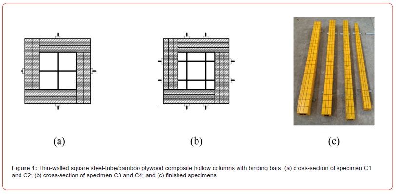
Table 1:Design parameters of specimens.

Test methods
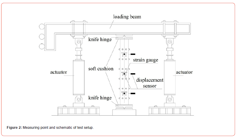
A multi-channel electro-hydraulic servo loading system was employed for the axial compression test; Figure 2 shows the test equipment and measurement point layout. Both ends of the test specimen were pressed by unidirectional knife hinges, and a cushion was placed between the column ends and the knife hinge plate to exert uniform pressure on the contact surfaces. Six displacement sensors for measuring lateral deflection, 12 axial strain gauges and 12 transverse strain gauges were placed near the upper, middle, and lower binding bars. The axial compressive load, displacement, and strain data were collected by the measurement system. Loading was applied using continuous low-speed uniform displacement loading. The test terminated when the specimen incurred large cracking damage, or a distinct unloading phenomenon was observed; the maximum load was assumed to be the ultimate axial load of the specimen..
Results and Discussion
Failure modes and mechanism analysis
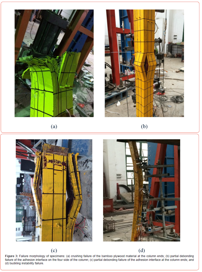
Column end bamboo plywood crushing failure: C1 showed column end bamboo plywood crushing damage (Figure 3a). Early in the loading process, the specimen did not show significant adhesive surface debonding or material cracking. When the axial compressive load was approximately 70% of the ultimate bearing load, the column surface of the bamboo plywood began to crack, accompanied by short, intermittent cracking sounds. With increasing load, the cracks gradually lengthened, and the bamboo plywood protruded outward. When approaching the ultimate bearing load, the end of the bamboo plywood column protruded outward, and crushing damage occurred. C1 had small slenderness, a large cross-section, and relatively large deformation stiffness. The binding bars were arranged in two rows with a small relative vertical spacing ratio (the ratio of the vertical spacing of the binding bars to the column side length), which improved the adhesive surface contact. Moreover, the binding bar and the inner steel tube showed a distinct hooping effect. Therefore, the failure mode of C1 was material damage, and the full strength of the bamboo plywood was utilized.
Partial debonding-peeling crimping damage: Specimens C2 and C3 showed the column partial debonding-peeling crimping damage failure mode (Figure 3b and Figure 3c). In the initial loading stage, the load was equally carried by different parts of the bamboo plywood structure due to the adhesive effect between the plywood and the steel tube; the deformation of these materials was approximately the same. When the axial compression load reached 50%–60% of the ultimate bearing load, the weak area between the binding bars experienced lateral deflection, and the normal tensile stress exceeded the surface adhesive strength, causing debonding cracks. As the load continued to increase, cracks continued to develop; thus, the remaining bamboo plywood had to bear all the pressure. When approaching the ultimate bearing load, the bamboo plywood that had peeled away from the weakened area bent outward and became crimped. Due to the constraint provided by the horizontal bars, only partial debonding peeling damage occurred. The bars withstood the force well, so shear deformation did not occur throughout the bars, and they restrained outward deformation of the plywood. In C2, which had two rows of binding bars with a relative spacing ratio of 2.0, the weak area was the center portion of the column. C3 had one row of binding bars with a relative spacing ratio of 2.5, and this specimen had a weak area at the end of the column. The actual weak areas may also be related to material property variations and initial defects. Compared to C1, specimens C2 and C3 had smaller cross-sectional areas, larger slenderness ratios, and smaller component stability. In addition, lateral debonding damage was the main failure mode for C2 and C3, which prevented the material strength of the plywood from being fully exploited.
Buckling instability failure: C4 showed the total buckling instability failure mode (Figure 3d). Specimen C4 had a relatively large slenderness ratio, a small cross-sectional area, and a low lateral stiffness. As the load slowly increased throughout the entire loading process, no evident adhesive surface or material cracking damage was observed. When the axial compressive load was close to the ultimate load, the lateral deflection in the middle of the column significantly increased. Furthermore, the longitudinal bending of the specimen eventually resulted in decreased loading capacity due to the lack of balance caused by the large column flexibility. Then, total specimen instability failure occurred, and the material strength of the plywood was not fully utilized.
Test results
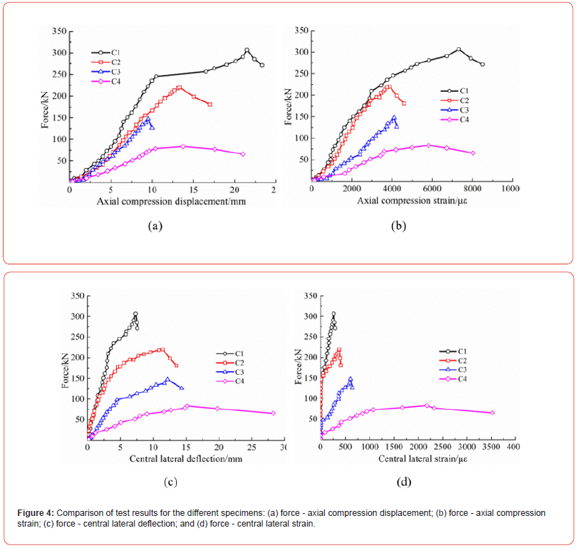
Figure 4 shows the test results of the axial compressive loading with axial and lateral displacements and strains. The bearing load in each stage decreased with increasing slenderness ratio and decreasing cross-sectional area. The larger the slenderness ratio was, the smaller the axial and lateral stiffness of the specimen were, and the shorter the elastic section of the axial deformation curve was. Thus, a large slenderness ratio produced early plasticity deformation and greater lateral deformation and strain. Specimens C1 and C2 had two rows of binding bars with a small vertical spacing and demonstrated better compressive loading performance. The hooping effect that formed between the binding bar and the thin-walled steel tube inside the column delayed not only the occurrence of cracks but also debonding failure in the local weak areas. Compared with the axial compression experimental results of the short steel tube/bamboo plywood hollow composite column with binding bars (SBCCBs) specimens, the slenderness ratio of the long SBCCB specimens had a greater influence on the bearing capacity. Because C4 possessed a larger slenderness ratio, the total instability failure occurred in the absence of debonding failure. Therefore, the SBCCB compressive capacity places an upper limit on the slenderness ratio; the maximum slenderness ratio needs to be determined from additional experiments.
Numerical Analysis
Material parameters
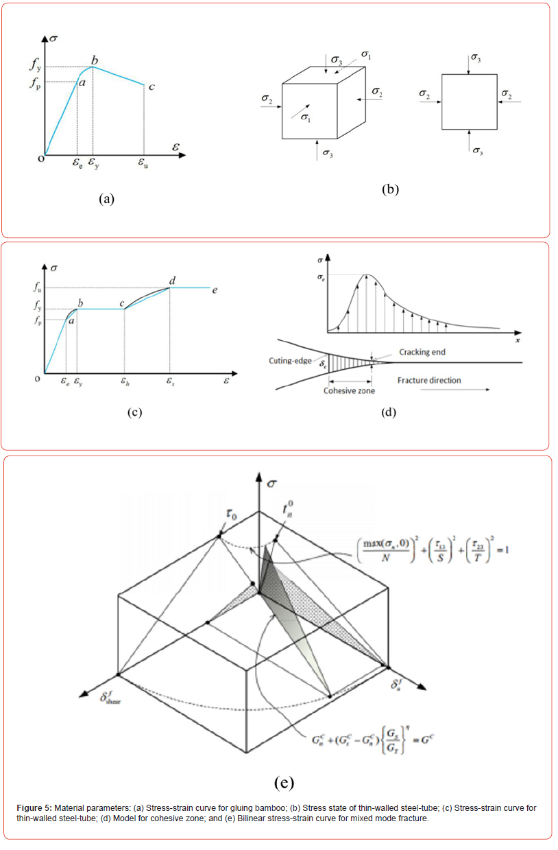
The specimen is composed of three types of materials, and the stress-strain relation model of the materials is determined first. According to our material property test results, the stress-strain curve of the bamboo plywood is shown in Figure 5a. The longitudinal and transverse tensile and compression curves have the same form; the only difference is the intersection locations of point a and point b, as shown in Table 2. The longitudinal load-bearing capacity of bamboo plywood is mainly compressive and tensile (side compression), basically involving the along-the-grain compressive and tensile elastic moduli and strengths. The transverse direction is mainly tensile and does not consider compression, mainly involving the cross-grain tensile elastic modulus and strength. The Poisson’s ratio in all three directions has a value of 0.3.
The thin-walled steel tube is typically under stress from three directions. However, since the steel wall is quite thin, the radial stress is much smaller than the stress in the other two directions; thus, the stress analysis can be performed in two directions (Figure 5b). The stress-strain curve of the steel material is shown in Figure 5c. The thin-walled steel tube is Q235; it has an elastic modulus of 205 GPa, an elastic strength of 235 MPa, a yield strength of 260 MPa, an ultimate strength of 340 MPa, a yield strain of 0.2%, a plastic strain of 0.5%, a maximum ultimate strain of 1%, and a Poisson’s ratio of 0.24. The stress-strain model for the thin-walled steel tube is the same as that for a steel tube.
The adhesive layer structural model is shown in Figure 5d. The actual crack tip is at the crack tip damage location. Assuming the maximum damage stress occurs at each crack tip, the constitutive relation of the model for the cohesion zone is the corresponding relation between the damage stress and strain at the crack tip. This relation is a mixed bilinear constitutive relation of a hybrid fracture mode (Figure 5e). Based on our test results, the limit pure shear strength of the steel-bamboo interface cohesion zone is σ1=σ2=τ13=τ23=6.37MPa, while that of the bamboo-bamboo interface cohesion zone is σ1=σ2=τ13=τ23=5.36 MPa. The limit pure tensile strength of the steel-bamboo interface cohesion zone is σc=σ3=1.51MPa, while that of the bamboo-bamboo interface cohesion zone is σc=σ3=1.15 MPa.
Table 2:Characteristic parameters of the stress-strain relationship for glued bamboo.

Finite element model and verification
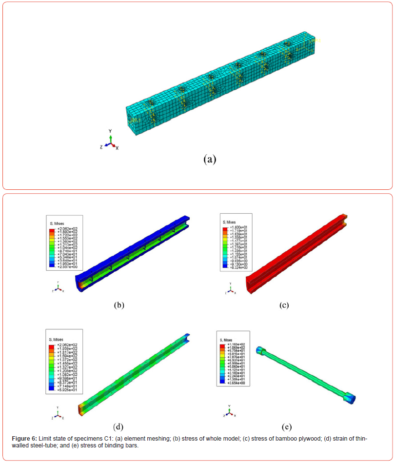
Few SBCCB specimens were tested in compression in these experiments. To study the compression load capacity, the finite element software package ABAQUS was used to simulate the test results and to extend the findings to the analyzed parameters. Figure 6a shows the total model meshing results for C1. Axial displacement applied to the top surface of the column while the plane displacement of the column bottom was constrained in three directions to simulate a fixed hinge base. Figure 6b ~ Figure 6e shows the limiting state stress cloud map for the C1 model. The plywood at the column end of C1 protruded outward, and the stress of the steel tube was the highest at the end. The same condition was observed in the experiments for specimen C1, with bamboo plywood crushing failure at the column end. For specimen C1, the total stiffness was high, and the constraining effect of the binding bar was significant; the specimen did not exhibit distinct adhesive surface debonding or material failure. The column material carried uniform stress when axial compression was applied, and the overall compressive performance was stable. Thus, the stress cloud map for various parts of the C1 model shows a smooth transition without distinct stress concentrations. The binding bars showed satisfactory load-bearing performance; shear damage never occurred during the process, which was consistent with the experimental results. Other models also can show a similar phenomenon observed in the experiments for specimen C2~C4.
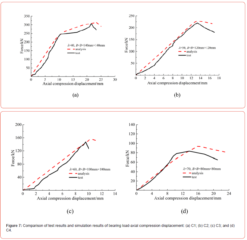
Figure 7 compares the simulated load vs. axial displacement curves and the experimental load vs. axial displacement curves of C1~C4, and these curves show very good consistency. All the load vs. axial displacement curves includes an increasing section and a decreasing section, which is an expression of the mechanical properties. The decreasing section shows the residual strength after the composite column reached its peak load; the negative stiffness phenomenon shown in the decreasing section of the simulated curve was similar to that shown in the experimental curve. Table 3 compares the ultimate loads from experiments Nu1 and from the simulations Nu2; the relative error between these values was ≤13.0%. Thus, the simulated and experimental results were similar, verifying the feasibility of the finite element model.
Parameter design and analysis
The orthogonal experimental method was employed to perform a numerical parametric analysis. The slenderness ratio, net crosssectional area, and number of rows of binding bars, and relative vertical spacing ratio for the binding bars were selected for this analysis. The net cross-sectional area was determined using the corresponding cross-sectional width B and the steel tube crosssectional width b. Only two rows of horizontal binding bars were needed to determine the actual dimensions of the specimen. The impacts of these four factors on the composite column ultimate load bearing capacity were investigated; the factors and their values are listed in Table 4.
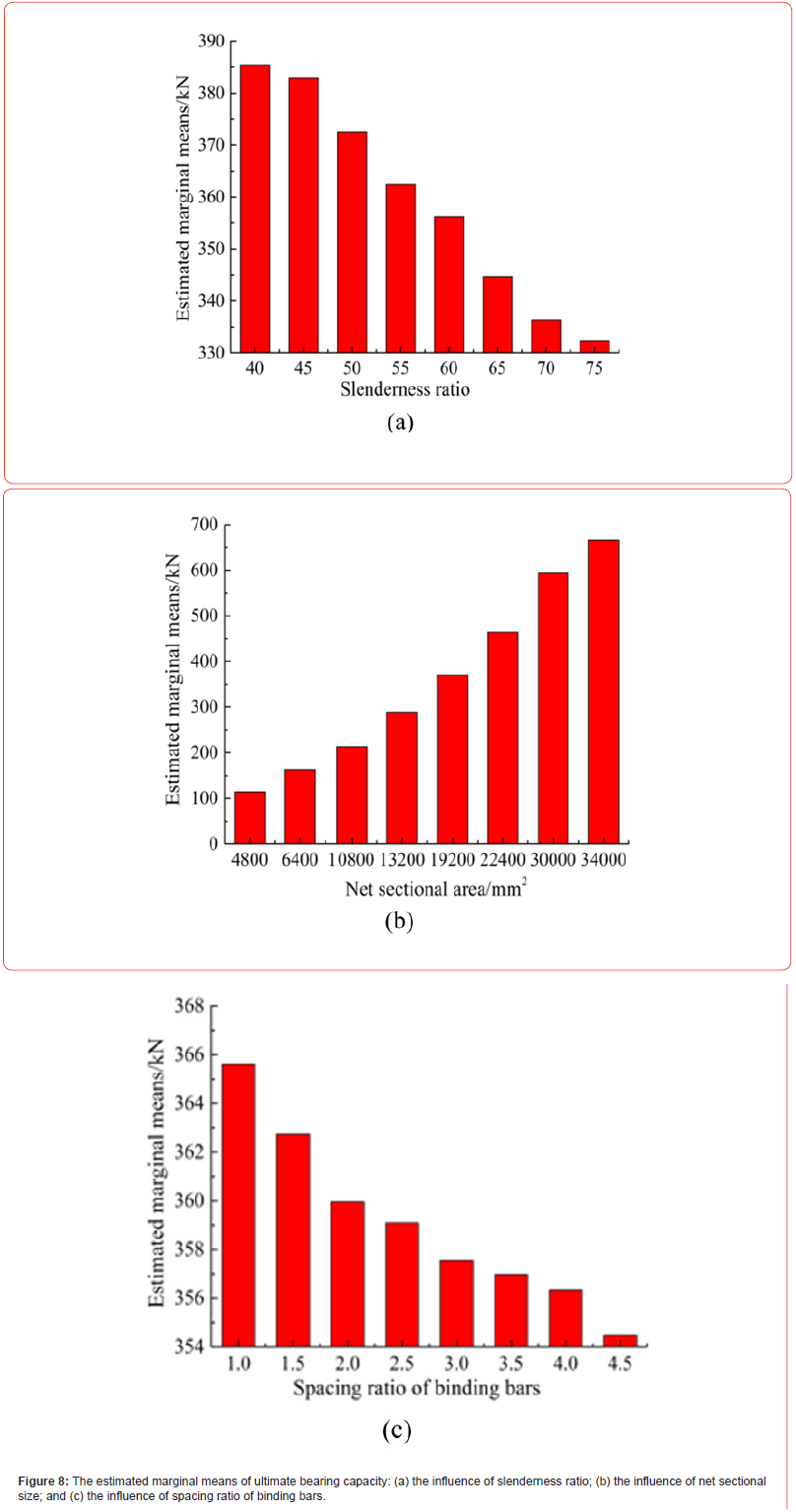
The statistical software SPSS was employed to perform a finite element simulation result variance analysis. The significant levels of the slenderness ratio, net cross-sectional area, and number of rows of binding bars were less than 0.05, indicating that these three factors significantly impact the ultimate load bearing capacity. The significant level of the binding bar relative vertical spacing ratio was 0.108, signifying that the impact of this factor on the ultimate load bearing capacity is relatively small. The impacts of these factors on the ultimate load bearing capacity have the following order of significance: net cross-sectional area, slenderness ratio, number of rows of binding bars, and binding bar relative vertical spacing ratio. As shown in Figure 8a, the larger the slenderness ratio is, the smaller the composite column ultimate load bearing capacity is. The slenderness ratio was divided into the following ranges: 40–45, 45–60, and 69–75; as the slenderness ratio increased, the ultimate load bearing capacity decreased. As shown in Figure 8b, the composite column ultimate load bearing capacity uniformly increased with increasing net cross-sectional area. Figure 8c indicates that the ultimate load bearing capacity decreased as the binding bar relative vertical spacing ratio increased. Increasing the number of rows of binding bars inhibited the debonding cracking damage of long composite columns and increased the ultimate load bearing capacity. However, only two rows were included in the numerical simulation in accordance with the actual condition, and the variation trend of this factor was not analyzed.
Table 3:Comparison of the tested values, analysis values, and calculated values.

Table 4:Parameter analysis of numerical simulations.

Calculation Model of Load-Bearing Capacity
The above analysis shows that the load-bearing capacity of an SBCCB increases as the net cross-sectional area of the bamboo plywood increases but decreases as the slenderness ratio increases. The hollowness of the specimens can reduce the slenderness ratio and improve the critical compressive load-bearing capacity of the specimens. Therefore, the hollowness can significantly improve the compressive load-bearing capacity, which is reflected in the slenderness ratio. The effects of the thin-walled steel tube area that can be transformed into the bamboo cross-sectional area are considered. Transverse binding bars can inhibit debonding failure, change the limiting damage mode and significantly improve the load-bearing capacity of SBCCBs, which is reflected in the regression parameters and is therefore considered as a separate factor. A formula for calculating the ultimate bearing capacity was created based on the experimental and finite element simulation results, the influence trend of each parameter on the ultimate bearing capacity, and the 64 finite element parametric analysis results. Four axial compression test results were used to verify the calculating model. The theoretical formulas (1) and (2) referred to the Chinese Code for the Design of Timber Structures [18], and the hooping constraint coefficient of the binding bar was employed to establish formula (3) which referred to the constraint coefficient of Reinforced Concrete column.
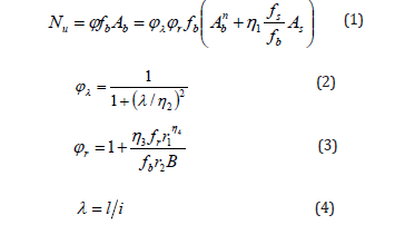
where, Nu is the load-bearing capacity for SBCCB; fb is the allowed value (24 MPa) for the compressive strength along the primary fiber direction of the bamboo mat plywood; fs is the strength (235 MPa) of thin-walled steel tube; Ab is the equivalent cross-sectional area of the compressed bamboo plywood; Abn is the net cross-sectional area of the bamboo plywood; As is the cross-sectional area of the thin-walled steel tube; i is the radius of gyration of the net crosssectional area of the composite column; ϕ is the total reduction coefficient; ϕλ is the influence coefficient of the slenderness ratio (stability factor); ϕr is the influence coefficient of the binding bar; λ is the slenderness ratio; l is the specimen length; B is the length of the cross-sectional side; r1 and r2 is the row number of binding bars, and the ratio of the vertical spacing of the binding bars to column side length, respectively; and η1, η2, η3 and η4 are the fitting parameters.
Using nonlinear regression analysis, the simplified parameters were η1=0.85, η2=71, η3=1.15, and η4=0.10, and the total correlation coefficient was R2=0.943. Among the 64 analysis results, the relative error for the four samples ranged from 20.1% to 24.3%, and the relative error for the remaining samples was ≤19.0%. The total analysis results were consistent with the experimental results. As shown in Table 3, the results of the four axial compression tests were used to verify the formal and showed a relative error of ≤13.4%, which corresponds with the simulation results. The regression fitting formula considered the influences of the number of rows of binding bars and the relative vertical spacing ratio; thus, the formula adequately reflected the variation characteristics of the ultimate load bearing capacity. The proposed formula is suitable for calculating the axial compressive bearing capacity of composite long columns with 40≤λ≤75.
Conclusion
Three axial compressive failure modes exist for long SBCCB specimens: column end plywood crushing, local debonding-peeling crimping, and total buckling instability. Both the slenderness ratio and the hooping effect formed by the horizontal binding bar and the thin-walled steel tube have important impacts on the failure mode. These two factors directly affect the degree of utilization of the plywood material strength. The effects of the examined factors on the SBCCB ultimate bearing capacity have the following order of significance: net cross-sectional area, slenderness ratio, number of rows of binding bars, and binding bar relative vertical spacing ratio. In addition to effectively inhibiting the debonding failure of a specimen, the binding bars also alter the ultimate failure mode and improve the ultimate bearing capacity.
The research results indicate that the bamboo plywood and the thin-walled steel tube can form a well-integrated composite column for supporting structures. The SBCCBs exhibited excellent compression performance, which indicates that bamboo plywood can be used as a modern structural material. A calculation model for the bearing capacity, which can serve as a guideline for engineering applications, was formulated based on the experimental and finite element simulation results. The influences of the number of rows of binding bars and the relative vertical spacing ratio are considered in the calculation of the SBCCB ultimate bearing capacity to comprehensively reflect the variation characteristics of the bearing capacity.
Acknowledgement
The authors gratefully acknowledge the financial support provided by the Science and Technology Planning Project of Guangzhou City (grant no. 201904010108) and the National Natural Science Foundation of China (grant no. 51708476).
Conflict of Interest
No conflict of interest.
References
- Mahdavi M, Clouston PL, Arwade SR (2011) Development of laminated bamboo lumber: review of processing, performance, and economical considerations. J Materials in Civil Engineering 23(7): 1036-1042.
- Xiao Y, Zhou Q, Shan B (2010) Design and construction of modern bamboo bridges. Journal of Bridge Engineering 15(5): 533-541.
- Hai-tao Li, Jing-wen Su, Qi-sheng Zhang, Andrew John Deeks, David Hui (2015) Mechanical performance of laminated bamboo column under axial compression. Composites Part B-Engineering 79: 374-382.
- Li Y, Chen ST, Meng X (2014) Compressive strength test on bamboo column reinforced by clamps. China Forestry Science and Technology 28(4): 113-115.
- Xiao Y, Shan B, Chen G, et al., (2009) Development of laminated bamboo modern structures. Proceedings of the 11th International Conference on Non-conventional Materials and Technologies, Bath UK, University of Bath, 2009.
- He Z, Zhou X, Xiao S, et al., (2018) Experimental investigation on bamboo columns under axial compression. Journal of Building Structures 39: 233-241.
- Yubing Leng, Qingfeng Xu, Kent A Harries, Lingzhu Chen, Kewei Liu, et al. (2020) Experimental study on mechanical properties of laminated bamboo beam-to-column connections. Engineering Structures 210: 110305.
- Yushun Li, Wei Shan, Huangying Shen, Zhen-Wen Zhang, Junzhe Li (2015) Bending resistance of I-section bamboo–steel composite beams utilizing adhesive bonding. Thin-Walled Structures 89: 17-24.
- Li Z, Xiao Y, Wang R, et al., (2014) Experimental studies of light-weight wood frame shear walls with ply-bamboo sheathing panels. Journal of Building Structures 34(9): 142-149.
- Verma CS, Chariar VM (2012) Development of layered laminate bamboo composite and their mechanical properties. Composites Part B-Engineering 43(3): 1063-1069.
- Wei Y, Zhou MQ, Yuan LD (2016) Mechanical performance of glulam bamboo columns under eccentric loading. Acta Materiae Compositae Sinica 33(2): 379-385.
- Bhavna Sharma, Ana Gatóo, Maximilian Bock, Michael Ramage (2015) Engineered bamboo for structural applications. Construction and Building Materials 81: 66-73.
- Liu X, Yu YS, Zhou WH (2013) Study on compression resistance of bamboo building structural column. Journal of Central South University of Forestry and Technology 33(1): 104-108.
- Xie QT, Zhang WL, Jiang TY, et al., (2012) Experimental study on performance of steel-bamboo composite column under axial compression. Engineering Mechanics 29: 221-225.
- Zhao WF, Cao YL, Zhou J, et al., (2015) Eccentric compression experimental study on square thin-walled steel tube/bamboo-plywood composite hollow column. Journal of Building Materials 18(4): 601-607.
- Zhao WF, Luo ZJ, Li YJ (2020) Axial compression testing of bamboo-laminated encased steel tube composite columns. Iranian Journal of Science and Technology, Transactions of Civil Engineering 44: 645-655.
- Cai J, Sun G (2008) Experimental investigation on L-shaped concrete-filled steel tube stub columns with binding bars under axial load. China Civil Engineering Journal 41(9): 14-20.
- GB 50005 (2003) Code for Design of Timber Structures. China Architecture & Building Press, Beijing, China.
-
Weifeng Zhao* and Jiguang Zhou. Compression Capacity of Long, Thin-Walled Steel- Tube/Bamboo-Plywood Composite Hollow Columns with Binding-Bars. Glob J Eng Sci. 11(4): 2024. GJES.MS.ID.000770.
-
Bamboo-plywood, Thin-walled steel-tube, Composite column, Axial compression, Bearing capacity
-

This work is licensed under a Creative Commons Attribution-NonCommercial 4.0 International License.


