 Research Article
2D and 3D Sensitivity Analysis of a Multitiered Retaining Wall
Sina Javankhoshdel1*, Sahand Shokri2, Moslem Rezvani2, Brigid Cami1 and Thamer Yacoub1
1Roc science Inc, Toronto, Ontario, Canada
2Rayan Geotechnics, Tehran, Iran
Sina Javankhoshdel, Roc science Inc, Toronto, Ontario, Canada.
Received Date: February 13, 2019; Published Date: March 15, 2019
Abstract
A rational design methodology for multitiered mechanically stabilized earth (MSE) walls that accurately predicts wall performance is lacking. AASHTO design guidelines provide a purely empirical design using “calibrated” lateral earth pressures adopted from various limited guidelines. Studies have shown that numerical analysis (limit equilibrium method (LEM) and 2D finite element method (FEM)) can be used for the analysis of these types of walls. In this study, a comparison of three different analyses of a multitiered retaining wall under surcharge loading is presented: 2D LEM, 3D LEM, and 2D FEM. The results showed that the 3D LEM gave higher factor of safety compared to the 2D LEM and 2D FEM which gave the same result. A sensitivity analysis regarding the strip coverage of the geosynthetic reinforcement layers is also presented in this study.
Keywords: Virtual Reality; Spatial visualization
Introduction
There are many situations where geosynthetic reinforced segmental retaining walls are constructed in a tiered configuration for a variety of reasons such as aesthetics, stability, and construction constraints, etc. For the bridge abutment application in particular, segmental retaining walls are frequently constructed in a tiered configuration. Although there have been a number of studies concerning geosynthetic reinforced retaining walls in tiered configurations [1-4], most of them focused on the effect of offset distance between upper and lower tiers on the wall performance during construction. In addition, no criteria for dealing with the effect of a surcharge load on a tiered geosynthetic reinforced segmental retaining wall are addressed in current design guidelines such as [5,6]. As the use of these retaining walls in bridge abutment construction increases, there is a need for an in-depth study on the response of a multi-tier geosynthetic reinforced segmental retaining wall to a surcharge load, which helps to accumulate relevant data to extend or refine the current design guidelines.
Leshchinsky D, et al. [1] used limit equilibrium method (LEM) and continuum mechanics-based (finite difference method) analyses to investigate the stability of multitiered reinforced segmental retaining walls. They showed that the limit equilibrium approach can be used to determine the required tensile strength and layout of reinforcement for the multi-tier mechanically stabilized earth (MSE) walls.
In this study, a multi-tier geosynthetic reinforced retaining wall under traffic loading is investigated using 2D LEM, 2D finite element method (FEM), and 3D LEM. The differences between the factors of safety and failure mechanisms in the three analyses are studied.
2D Vs 3D Critical Factor of Safety and Failure Mechanism
Figure 1 shows an example of a 2D multi-tier retaining wall and its critical slip surface corresponding to the lowest factor of safety. In this example, for the backfill and reinforced soil cohesion is 0 kPa and friction angle is 38° and unit weight is 18 kN/m3 and for the foundation soil cohesion is 5 kPa and friction angle is 34° and unit weight is 18 kN/m3. Reinforcement layers are geotextiles with the tensile strength of 40 kN/m.
In this example, the maximum spacing of the reinforcement layers is limited to 0.6m (recommended by AASHTO). It is assumed in the analysis that the traffic load of 50 kN/m2 for the length equal to the reinforcement length is applied to the retaining wall (recommended by AASHTO).
Figure 1 shows the results of the non-circular LEM using Cuckoo Search method together with the Surface Altering Optimization (SAO) technique. The Cuckoo Search method is a general optimization technique that optimizes the surfaces found using Morgenstern-Price method as a base search method to find the critical slip surface. On the other hand, SAO is a local optimization method used to refine the critical slip surface in the non-circular LEM analysis. Slide2 [7] software was used to compute this example.
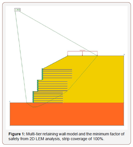
The first observation from Figure 1 is that the failure mechanism is not circular. The deterministic factor of safety is 1.4 which is close to the design factor of safety recommended by design standards (1.5 for reinforced retaining structures).
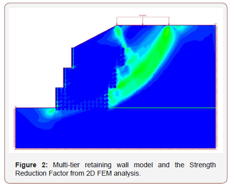
To confirm the results of the LEM in Figure 1, the same model was computed using FEM, with the software RS2 [8] which uses Shear Strength Reduction (SSR) to find the critical factor of safety (Figure 2). To model geosynthetic reinforced layers, beam elements were used with joints as the interface of the reinforcement layers and their surrounding soil. The failure mechanism appears to be similar to the non-circular LEM. The calculated factor of safety of 1.42 is also similar to the factor of safety calculated using the combined Cuckoo Search method and SAO.
In order to obtain a better understanding of the failure mechanisms, it is always recommended to look at a model in 3D. Slide3 [9] is the 3D LEM software. To get the 3D model, the 2D model was transferred from the Slide2 2018 software to the Slide3 2019 software, the only additional step was to define the third dimension which is assumed to be 30m for this case.
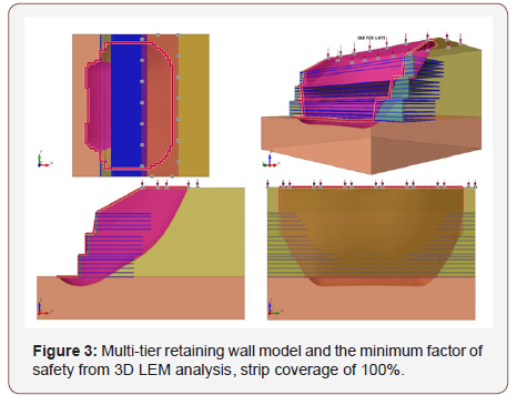
Figure 3 shows the 3D model with the failure surface corresponding to the minimum factor of safety in the Slide3 software. In this software, Cuckoo Search method with the Ellipsoidal surface and SAO was used to find the critical slip surface. The factor of safety for the 3D model was found to be 1.68.
Comparing Figures 1,2 & 3 shows that the 3D model gives higher factor of safety compared to the 2D models. It can be argued that using 2D methods is conservative or an under estimation of reality. But for more complicated geometries, considering the whole model as a 3D structure finds its added value in the engineering calculations. However, it is interesting to note that the failure mechanism and the location of the intersection of the critical slip surface with the reinforcement layers is very similar in Figures 1 & 3. This is due to same way in which geosynthetic reinforcement layers are considered in 2D and 3D LEM.
Strip Coverage Sensitivity Analysis
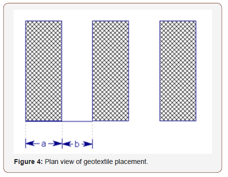
When a geosynthetic is used to reinforce a slope, the material is placed in strips of a certain width. The strip coverage refers to the spacing of these strips, in the Out of Plane direction (i.e. along the slope). If the strips are laid continuously beside each other, with no gaps between adjacent strips, then the strip coverage = 100%. If the strips are not laid continuously (i.e. there are spaces between adjacent strips), then strip coverage will be less than 100%. For example, if 4-meter-wide strips were laid with a 2-meter spacing between each strip, then the strip coverage would equal 67% (i.e. strip coverage = (a / (a + b)) x 100 which is 4 / (4 + 2)*100) (Figure 4).
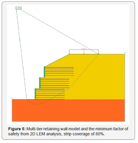
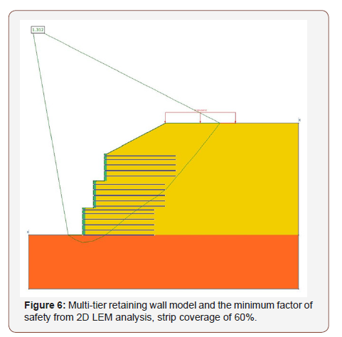
To investigate the influence of the strip coverage on the factor of safety and the critical failure mechanism in 2D and 3D, three different cases of strip coverage = 100%, 80% and 60% have been investigated in 2D and 3D. Figures 1 & 3 are for the strip coverage of 100% in 2D and 3D, respectively.
Figures 5 & 6 are 2D cases with the strip coverage of 80% and 60%, respectively and Figures 7 & 8 are 3D cases with the strip coverage of 80% and 60%, respectively.
Comparing Figures 1,5 & 6 shows that, as the strip coverage decreases the factor of safety decreases as well i.e. 1.41,1.36 and 1.31 for the cases with the strip coverage of 100%, 80% and 60%, respectively. The amount of decrease in factor of safety from 100% strip coverage to 80% and from 80% to 60% is about 4%. It can be seen in theses figures that, as the strip coverage decreases, the number of reinforcement layers intersecting the critical slip surface increases).
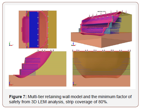
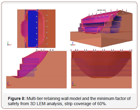
In the 3D case, the same trend can be observed. Comparing Figures 3,7 & 8 shows that, as the strip coverage decreases the factor of safety decreases as well i.e. 1.68,1.57 and 1.53 for the cases with the strip coverage of 100%, 80% and 60%, respectively. However, the amount of decrease is different from 2D, i.e. the amount of decrease in factor of safety from 100% strip coverage to 80% strip coverage is about 7%, while it is 3% from 80% strip coverage to 60% strip coverage. The reason might be the 3D modeling of the reinforcement layers as a 3D surfaces compared to the 2D reinforcement layers which are horizontal forces only. Similar to the 2D cases, as the strip coverage decreases, the number of the reinforcement intersection the critical slip surface increases.
Conclusion
Researchers showed that numerical analysis (LEM and FEM) can be used for the analysis of multi-tier geosynthetic MSE walls. In this study, a comparison between the 2D and 3D LEM analysis and 2D FEM analysis of a multitiered retaining wall are presented.
Results showed that, although the critical slip surface between the 2D and 3D models is similar, the 3D LEM analysis gives higher factor of safety compared to the 2D cases, i.e. 2D models are more conservative for design purposes.
Investigating the influence of strip coverage on factor of safety showed that as the strip coverage of geosynthetic reinforcement layers decreases the factor of safety also decreases in 2D and 3D LEM models. However, the amount of reduction is more in the 3D LEM compared to the 2D LEM model because of the difference between the modeling of 3D geosynthetic surfaces compared to the 2D geosynthetic forces only.
Acknowledgement
None.
Conflict of Interests
No Conflict of Interest.
References
- Leshchinsky D, Han J (2004) Geosynthetic reinforced multitiered walls. Journal of Geotechnical and Geoenvironmental Engineering 130(12): 1225-1235.
- Yoo CS, Kim JS (2002) Effect of foundation stiffness on behavior of soil reinforced segmental retaining walls. Journal of Korean Geotechnical Society 18(8): 7-19.
- Yoo C, Jung HS (2004) Measured behavior of a geosynthetic-reinforced segmental retaining wall in a tiered configuration. Geotextiles and Geomembranes 22(5): 359-376.
- Yoo C, Song AR (2006) Effect of foundation yielding on performance of two-tier geosynthetic reinforced segmental retaining walls – a numerical investigation. Geosynthetics International 20(3): 110-120.
- FHWA (2001) Mechanically Stabilized Earth Walls and Reinforced Soil Slopes, Design and Construction Guidelines. Federal Highway Administration Publication No. FHWA-NHI-00-043, US Department of Transportation, Washington DC, USA, pp. 418.
- NCMA (1997) Design Manual for Segmental Retaining Walls, second ed. National Concrete Masonry Association, Herndon, Virginia, USA, pp. 289.
- Rocscience (2018) Slide2 Version 2018 - 2D Limit Equilibrium Slope Stability Analysis. Toronto, Ontario, Canada.
- Rocscience (2019a) RS2 Version 2019 - 2D Finite Element Analysis. Toronto, Ontario, Canada.
- Rocscience (2019b) Slide3 Version 2019 - 3D Limit Equilibrium Slope Stability Analysis. Toronto, Ontario, Canada, pp. 1-5.
-
Sina Javankhoshdel, Sahand Shokri, Moslem Rezvani, Brigid Cami, Thamer Yacoub. 2D and 3D Sensitivity Analysis of a Multitiered Retaining Wall. Glob J Eng Sci. 1(5): 2019. GJES.MS.ID.000522.
-
2D and 3D, Sensitivity, Analysis, Multitiered retaining wall, Segment, LEM, MSE, FEM
-

This work is licensed under a Creative Commons Attribution-NonCommercial 4.0 International License.


