 Research Article
Tests Carried Out on Roads Containing Steel Mill Slag
Ion Chiricuţă* and Ion Rusu
Department of Civil Engineering, Technical University of Moldova, Republic of Moldova
Ion Chiricuţă, Department of Civil Engineering, Technical University of Moldova, Republic of Moldova
Received Date: November 15, 202; Published Date: November 29, 2023
Abstract
In order to study the behavior over time of roads where steel mill slag has been used, it is important that tests are carried out on them, by which to be determined the characteristic deflection (by measurements using the Benkelman beam) and the deformation module (by tests performed with the Lucas plate). This allows us to analyze the viability of using steel mill slag in road structures, by comparing the results obtained with the values allowed in the regulations. The test with the Lucas plate is intended for use in earthworks and foundation engineering, as well as in road construction. The method permits the relationship between load and settlement (load-settlement curve) to be determined, the aim being to assess the deformation and strength characteristics in order to determine the deformation modulus.
Keywords: Deformation modulus; foundation layer; loading; Luca’s plate; relative deformation
Introduction
This article shows the results of the tests carried out with the Lucas plate in different areas of the national road DN 2B Galati - Giurgiulesti, which was made using steel mill slag, in order to establish if the steel slag had an adequate behavior in exploitation and could be an alternative for the natural aggregates [1]. Steel slag is the main solid waste in steel industry, accounting for more than 10% of the steel production [2]. According to the different steelmaking processes, steel slag can be classified into three types: electric arc furnace (EAF) slag, basic oxygen furnace (BOF) slag and ladle furnace (BF) slag. The large capacity of steel slag can meet the needs of aggregates for road construction, and it has good mechanical properties and high alkalinity [3]. There are very few published papers on the Lucas plate tests. An excellent report was published in the Republic of Moldova by the company Universinj - Design, Engineering, Consulting, having as its object the study of the bearing capacity of the foundation land of the embankments and the determination of the physical-mechanical properties of the soils in the composition of the road complex of the road R21 Orhei Bravicea- Călărași, sector km 21.20-34.20 [4]. Also, in “Revista Constructiilor” from 04/05/2017 there is a brief reference to a test carried out with Lucas plate type TESTING 30203 PDK-K, a test that allowed the determination of the static modulus of deformation, as well as the establishment of compression settlement curves, based on to which the deformation and bearing capacity of the earth were assessed [5]. DN2B is a national road in Romania that connects the cities of Buzau and Galați. The road starts from DN2 in the town of Spătaru, 8 km from Buzău, passing through the industrial area of this city and heading east. The road bypasses the town of Brăila, passes the Siret and reaches Galati. After leaving Galati, DN2B heads towards the border with the Republic of Moldova, connecting in the Giurgiulesti area to the R34 road from Moldova. The road layers are as follows: 35 cm foundation layer of steel mill slag grade 0-63 mm and 20 cm crushed stone layer. The study of the bearing capacity of the road complex is motivated by the fact that a long period of time has passed since the construction of the road, and the condition of the road surface has undergone changes both in terms of the state of degradation and the thickness of the road layers.
Methods and Procedures
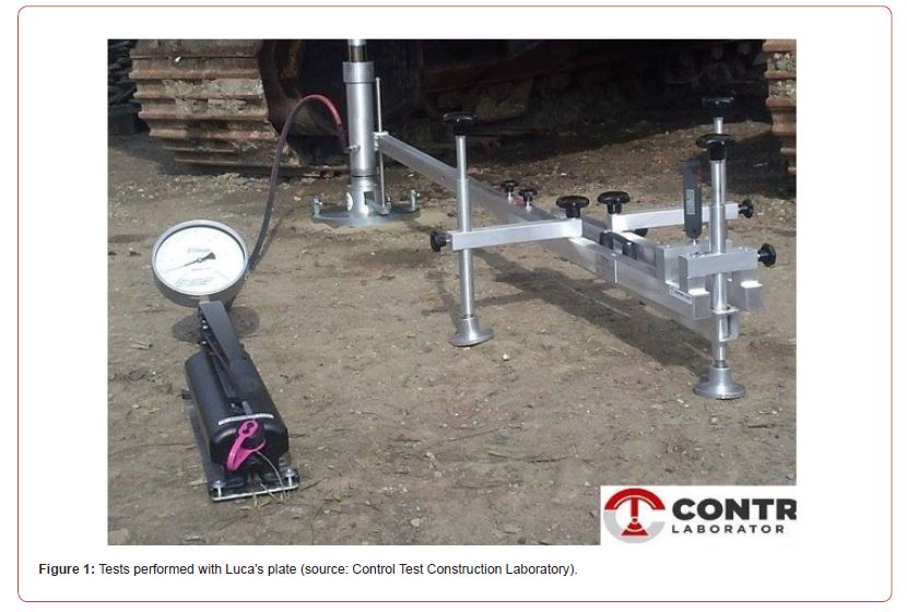
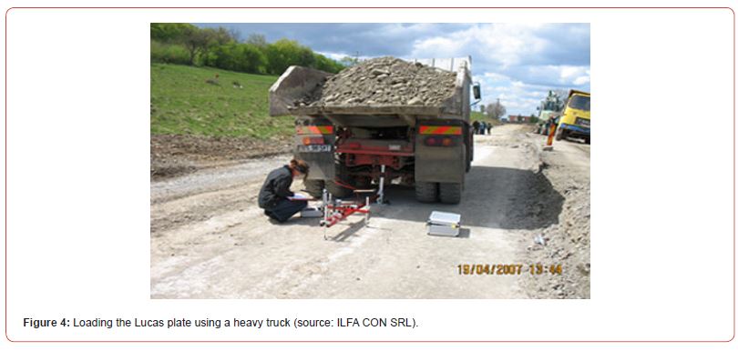
The equipment for carrying out the test consists of ballasting or anchoring devices, reference frames, rigid circular plate, hydraulic press, hydraulic pump with pressure gauge and a first-order lever type device to which is attached a micro comparator with a measurement accuracy of 0.01 mm. The device measures the settlement of the rigid plate under the effect of an incrementally applied load in steps [6]. The devices described before are shown in Figures 1-4. The test consists in applying vertical loads, in steps of 101.4 kPa, on a rigid plate with a diameter of 500 mm placed on the surface to be loaded and measuring the settlements of this surface, after each step of loading. Each load is maintained until the settlement is stabilized [7]. Settlements are measured on the upper surface of the slab in at least three points, arranged near the contour of the slab. The differences between the readings on the settlement measuring devices must not show deviations from the average settlement (arithmetic mean of the readings) greater than 30%. Otherwise, the test is considered inconclusive. The test is stopped after obtaining an effective relative deformation greater than the calculation relative deformation [8]. The calculation values of the relative deformation depending on the type of road system are shown in Table 1.
Table 1:Calculation values of the relative deformation depending on the type of road system.

The effective relative deformations s’ corresponding to each load step are calculated with the relation:
s’ = s / d (1)
where: s is the average settlement and d is the diameter of loading plate.
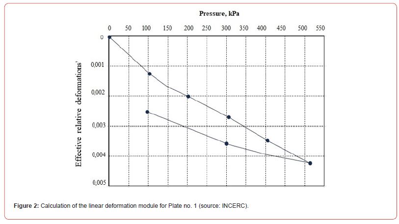
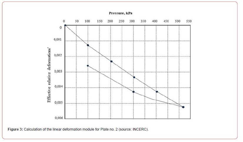
In the present case, the calculation relative deformation value s’ is 0.001. The values obtained by the three determinations at the same load level are compared. They must not differ from each other by more than 10% in absolute value. Otherwise, the test is considered inconclusive. The test results are the arithmetic averages of the values obtained through the three determinations. The stress shall be plotted against the settlement, as shown in Figures 2-4. A smooth curve shall be drawn through the measuring points for each cycle. With the calculation values of the relative deformations, enter the pressure - effective relative deformations diagram and establish the pressures corresponding to these deformations.
The linear deformation modulus is calculated with the relation:
E = p / s’, kP (2)
where: p is the applied pressure and s’ is the effective relative deformation.
Test No. 1
Location: km145+624; P 163 1m to the left of the road axis.
Test results for Plate no. 1 are shown in Table 2 and represented in Figure 2. The intersection points of the horizontal line corresponding to s’ = 0.001 with the diagram corresponds to a value of the design pressure of 78 kPa, with the help of which the linear deformation modulus is calculated: Ed =780 daN/cm2.
Test No. 2
Location: km145+638; P 163 + 14m 3.25 m to the left of the road axis.
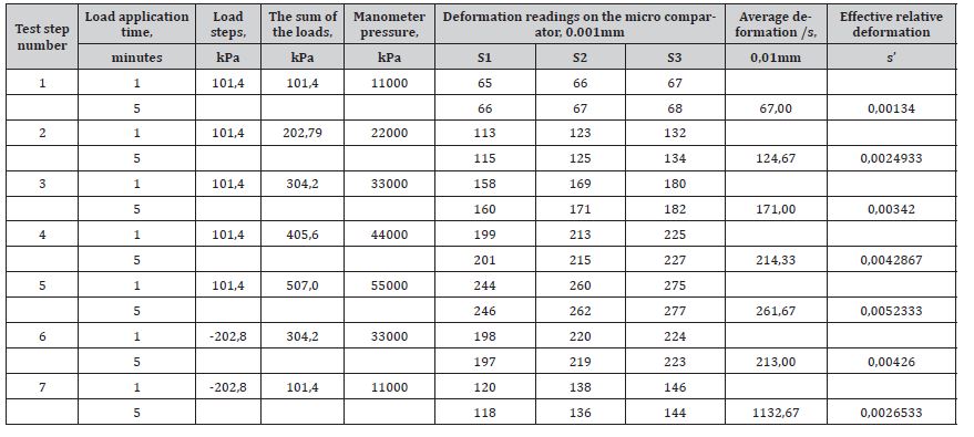
Test results for Plate no. 1 are shown in Table 3 and represented in Figure 3. The intersection points of the horizontal line corresponding to s’ with the diagram corresponds to a value of the design pressure of 78 kPa, with the help of which the linear deformation modulus is calculated: Ed = 750 daN/cm2.
Table 2:Test results for Plate no. 1.
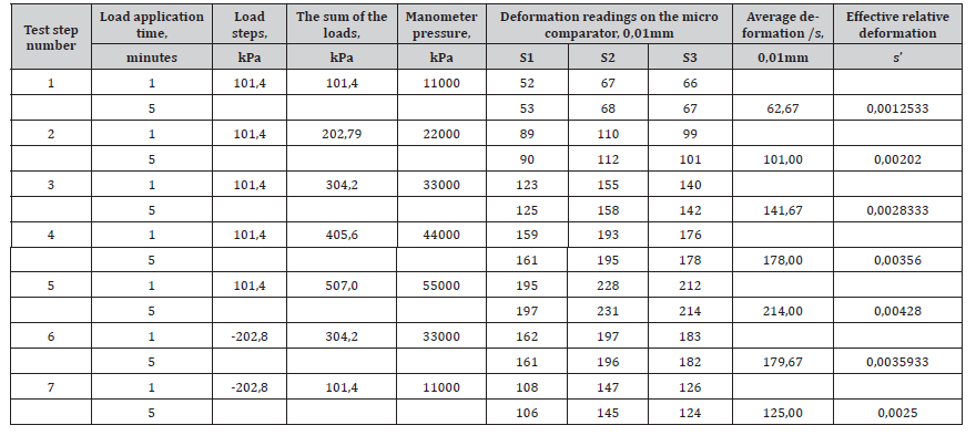
Table 3:Test results for Plate no. 2.
Test No. 3
Location: km145+652; P 164 1 m to the left of the road axis.
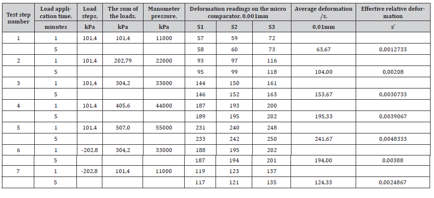
Test results for Plate no. 3 are shown in Table 4 and represented in Figure 5. The intersection point of the horizontal line corresponding to s’ = 0.001 with the diagram corresponds to a value of the design pressure of 78 kPa, with the help of which the linear deformation modulus is calculated: module Ed = 760 daN/cm2.
Table 4:Test results for Plate no. 3.
Results and Discussion
In order to establish if the mill slag can properly replace the natural aggregates in road layers [9], the above calculation values of the deformation modulus must be compared with those corresponding to the materials indicated in NP 081 - 2002 [10], according to Table 5. It is found that the values obtained for the linear deformation modulus for road layers consisting of steel mill slag [11], according to the three tests performed (750 daN/cm2, 760 daN/cm2 and 780 daN/cm2), exceed the calculation values of the deformation module for all types of ballast and are at least equal to the value specified for the ballast - optimal mix for the foundation (750 daN/cm2), which are shown in the previous table. The results of the test are presented in a report that shall include the following information: location of test site; diameter of loading plate; type of settlement-measuring device used; weather conditions; time and date of measurements; time of start and completion of test; any unusual observations made during the test; dial gauge readings and corresponding normal stresses; load-settlement curves [12].
Table 5:Calculation values of the deformation modulus.

Road construction involves large quantity of construction materials, most of them obtained from natural sources. To achieve a sustainable development, using the steel slag as a substitute for natural aggregates must be taken very seriously. More than 90% of this is asphalt pavement, which has the advantages of low vibration, low noise, short construction time and convenient maintenance. Expressway need lots of construction and maintenance, and more than 90% of the components of asphalt pavement are aggregates, which causes the depletion of natural resources. Therefore, recycling solid waste and industrial melting waste are becoming an effective option to relieve the supply pressure of natural aggregate resources. The steel slag mixture has become an increasingly popular research topic in the field of environmental protection road materials in recent years and future researches will certify that using of it is very advantageous [13].
There are also some disadvantages of using steel slag in road layers, as follows:
a) The risk of heavy metals in the steel slag aggregates, which could be washed away by rainwater, thus infesting the groundwater [14]. To eliminate this risk, it is recommended that a leaching test be performed by a specialized institute [15].
b) Possibility of volume change (increase or decrease in road layer height) due to hydration of free calcium oxide [16]. To eliminate this risk, the best possible waterproofing of the upper layers and appropriate drainage works are recommended, in order to prevent the penetration of rainwater into the base or foundation layers of the road system [17], as well as the maturation of the slag before use, by storage in outdoors and periodic spraying with water [18].
Conclusions
Having in view the above presented tests and their results, we can therefore conclude that steel slag can successfully replace the natural aggregates in the layers of a road structure, showing a high performance, if all the necessary conditions are met, with all the advantages that come from it. By replacing the natural aggregates in the foundation layer and the base layer of the road system with steel mill slag, a significant decrease in the cost of the works was achieved (slag, being an industrial waste, is much cheaper than natural aggregate). Also, the use of slag aggregates results in the protection of the environment, by eliminating slag storage spaces and by preserving the natural environment (the extraction of natural aggregates can disturb the ground water, can accentuate erosion, etc.).
References
- Selih J (2004) The Use of Waste Materials in Building and Civil Engineering, Mater. Techno. Ljubljana 38 (1-2): 79-86.
- Finnra (2000) Renovation of Gravel Roads. Long-term Performance and Economy. Tielaitos, Tuotannon T&K, Oulu, Finlandpp. 39-41.
- Chiricuţă I (2021) Replacement of Natural Aggregates Used in Road Structures with Steel Slag. Journal of Engineering Science 28(2): 120 – 124.
- Universinj Design, Engineering, Consulting: Raport de Incercari - Licenţă seria A MMII nr. 020953.
- (2017) Metode de verificare, cu placa dinamica, a capacitatii portante a terenului - Revista Constructiilor.
- Constantinescu V (2001) Tehnologii performante şi echipamente pentru realizarea structurilor rutiere, Ed. Impuls, Bucureşti, pp. 112-113.
- Andrei B (2006) The study of road foundations treated with different hydraulics. Thesis, pp.37.
- STAS 2914-4-89 Determination of the Linear Deformation Modulus.
- (2002) Feasibility study for the preparation and exploitation of slag from the Buituri dump - SC Geasol SA pp. 53-56.
- (2002) Normativ de dimensionare a structurilor rutiere rigide.
- Kavalevova ES, Petropavlovsky OM (2000) The Use of Steel Melting Slags in Earth Construction. A Paper for the International Conference on Practical Applications in Environmental Geotechnology, Ecogeo, Helsinki, pp. 34-35.
- (2001) DIN 18134 Determining the deformation and strength characteristics of soil by the plate loading test.
- Pasetto M, Baldo N (2010) Experimental evaluation of high performance base course and road base asphalt concrete with electric arc furnace steel slags. J Hazard Mater 181: 940-948.
- Cososchi B (1998) The impact of transport on the environment. "CERMI" publishing house pp. 101-102.
- Tsohos G (2004) Utilization of by products and alternative materials in road construction. Proceedings of the Conference on use of industrial by-products in road construction, Thessaloniki pp. 7-15.
- Rusu I, Chiricuţă I (2014) Reducing the environmental impact of steel mill slag by using it in road structures – 14th National Congress of Roads and Bridges, Cluj-Napoca pp. 1-3.
- Motz H, Geisler J (2001) Products of Steel Slags and Opportunity to Save Natural Resources. Waste Manage 21: 285-293.
- (2001) LIDONITE - Aggregates from DSU Galati steelworks slag, pp. 9.
-
Ion Chiricuţă* and Ion Rusu. Tests Carried Out on Roads Containing Steel Mill Slag. Cur Trends Civil & Struct Eng. 10(2): 2023. CTCSE.MS.ID.000733.
-
Deformation modulus; foundation layer; loading; Luca’s plate; relative deformation; Iris Publishers; Iris Publishers Indexing sites
-

This work is licensed under a Creative Commons Attribution-NonCommercial 4.0 International License.


