 Research Article
Subdomain Method for Layout Optimization of Piles in a Composite Pile Foundation
Jiao Shi1, Pengfei Wang1and Kun Cai2*
1College of Water Resources and Architectural Engineering, Northwest A&F University, China
2Centre for Innovative Structures and Materials, School of Engineering, RMIT University, Australia
Kun Cai, Centre for Innovative Structures and Materials, School of Engineering, RMIT University, VIC 3001, Australia.
Received Date: September 16, 2019; Published Date: September 25, 2019
Abstract
Based on continuum topology optimization, a subdomain approach for achieving optimal pile layout in a composite pile foundation (CPF) is presented. In general, the computational time is excessively long when the span of a CPF is far greater than the depth of pile and the nonlinearity of soils and soil-pile contact are considered. To reduce computational time, we suggest dividing the original pile foundation into a number of subdomains. Only a few representative subdomains (RSs), such as the corner representative subdomain (CRS), side representative subdomain (SRS), and inner representative subdomain (IRS), are required to find the optimal pile layout through topology optimization. In optimization, the pile volumes, maximum settlement, and settlement uniformity of foundation surface are considered simultaneously. Numerical experiments are presented, and the validity of the algorithm is verified. In the present method, a CPF with an initial uniform layout of piles of the same length becomes the foundation for heterogeneous layouts and long/short piles. The final design also depends on the inter-pile distance.
Keywords: BComposite foundation; Topology optimization; Pile foundation; Subdomain method; Settlement
Introduction
Composite foundation is widely used in civil and hydraulic engineering [1,2]. Accurate estimations of pile-bearing capacity and settlement are required in the design of a pile foundation. Hence, in the design of a composite pile foundation (CPF), two major factors are usually considered. One is the materials properties of soil and piles comprising the CPF; the other is the layout of piles in the foundation. To improve the bearing capacity of a CPF more piles can be added or the friction between soil and pile can be increased. These two factors have received considerable attention in the study of CPFs through in-situ experiments. For instance, Wang et al [3] presented an analysis of the bearing capacity of piles and soil in a multiple composite foundation using an in-situ experiment. Tamura et al [4] applied cyclic lateral-loading centrifuge tests to investigate the effect of a new pile added at the center of existing piles on the new pile’s lateral resistance. Bao et al [5] studied the seismic enhancement effect of group-pile foundation on the partial ground improvement using both a shaking table test and numerical simulation. Subsequently, Suzuki et al [6] simulated the pile-soil effect under seismic load and revealed the effects of loading distribution on the mechanical behavior of piles. Gotman & Khurmatullin [7] experimentally investigated the performance of vertically loaded soil-cement piles installed by a jet-grouting procedure in clayey soils.
Besides in-situ experiments, numerical simulations have often been adopted in practical design to investigate the response of a CPF using mechanical models of soil and pile and the coupling effect between soil and pile built-in in-situ test. For example, Ge et al [8] studied the response of a long/short-pile composite foundation under certain loading using finite element method. Bao et al [5] studied the seismic enhancement effect of group-pile foundations using a partial ground improvement method. Shahin [9] investigated the load-settlement response of steel driven piles under axial load using CPT-based recurrent neural networks. Hariri-Ardebili [10] used a simulation method to predict the effects of a nonlinear foundation on the crack of either a gravity dam or an arch dam under seismic load. Zhou et al [11] analyzed the stress and displacement near a rectangular rigid plate supported by laterally loaded rectangular cross-sectional piles in an infinitely elastic soil using a conformal mapping method. Using finite element software ABAQUS, Rose et al [12] presented a numerical investigation of the dependency of pile-group behavior on such factors as number of piles, pile spacing, length/diameter ratio, and soil strength. To obtain a more effective and rational reinforcement foundation in water, Isobe et al [13] proposed a steel pipe sheet pile reinforcement method, and the static lateral bearing capacity and seismic performance of reinforced foundations were investigated by three-dimensional elastoplastic finite element method. Gotman [14] examined the stress-strain state of a horizontally loaded foundation with inclined precast piles sunk into a tamped-in pit and proposed a computational scheme.
In the traditional design of a CPF, bearing capacity and settlement are considered separately. In fact, soil resistance and settlement have a coupling effect and, therefore, simultaneous consideration of the two factors should produce a more reasonable CPF design [2]. In particular, the control of uniform settlement is more significant. Traditionally, the piles are laid out with the same spacing. Sometimes the lengths of piles are identical. It should be mentioned that the pile-group effect leads to non-uniform settlement of such pile foundations [15]. With this feature as inspiration, optimization of pile layout, both of positions and lengths of piles, is important for controlling uniformity of settlement. Continuum optimization theory [16-20] is a powerful computational tool for finding the optimal layout of a CPF. Following this line, Sheng and Qiu [21] developed a topology optimization method that could achieve the optimal layout of equal-length piles in a foundation. However, their method could only identify the positions of a few piles. Chan et al [22] carried out the pile group optimization using fully stressed design-controlled genetic algorithm. The major reason for this deficiency is that the computational cost is too high in the pile layout optimization of a CPF. The computational cost usually depends on three factors: (1) the foundation size may be far greater than the pile length; (2) material nonlinearity and state nonlinearity of soils and piles may exist, leading to a large amount of structural reanalysis when searching for an acceptable deformation configuration of the foundation; (3) the number of design variables in topology optimization may be too large for it to be solved directly by any traditional method. To bypass these difficulties, in the present study a subdomain method integrated with topology optimization models is proposed for achieving the optimal pile layout in a CPF with uniform settlement.
Methodology
Mesh scheme of subdomains in a CPF
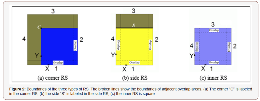
In the pile layout design of a CPF, the whole structure is assumed to be composed of a slab foundation, piles and soils. When such a structure is used in an airport or a highway, its horizontal size is far greater than the depth of its piles. If we take the whole structure as a design domain, the computational cost would be too high to be acceptable in practical engineering. Furthermore, the final pile layout obtained by such approach is commonly not feasible for the final design, because the pile layout is significantly non-uniform, which can lead to severe differences in settlement of the foundation. Therefore, a critical need exists to reduce the computational cost before carrying out pile layout optimization. It is noted that, in continuum topology optimization, the computational cost depends on two major factors. The first is the analysis of structural deformation and the second is the updating of design variables. Based on this understanding, a subdomain approach is proposed in the present study to reduce computational time. The major principle of the subdomain method is to mesh the whole CPF into many square subdomains first (Figure 1). Considering computational cost and accuracy, the lengths of horizontal sides of each subdomain should be no more than 10 times of the minimal pile distance. On the other hand, to demonstrate variation of topology of pile layout in a subdomain, the horizontal side lengths should also be no less than 3 times of the minimal pile distance. Then, these subdomains are classified into 3 groups, corner subdomains, side subdomains and inner subdomains. In each group, at least one RS should be chosen. As an example, the foundation shown in Figure1A is meshed with 4 corner subdomains (dark blue), 18 side subdomains (yellow) and 18 inner subdomains (light blue). Each group has one RS, namely a corner RS (CRS), a side RS (SRS), and an inner RS (IRS). The boundaries of the three RSs are illustrated in Figure 2. Next, we need to determine the optimal layout of piles in each RS using topology optimization. Finally, we assemble the final piles layout in the whole foundation using the RSs.
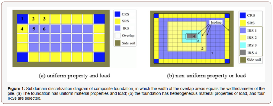
There are two merits of this method. One is high efficiency, in that only few RSs are required to optimize the layout of piles. The other is that the pile layout is uniform in the initial whole foundation (rather than in each subdomain). It should also be noted that the RSs must be determined accurately in order to find the final pile layout of the foundation based on this subdomain method if the spatial distribution or material properties of soils or load are not uniform in the foundation. For illustration, Fig.1b shows a mesh scheme of subdomains in a CPF that has non-uniform mechanical properties of soil. In accordance with the isolines of the soil’s mechanical properties, we define four IRSs (in different colors) (Figures 1,2).
Overlap between neighbor subdomains
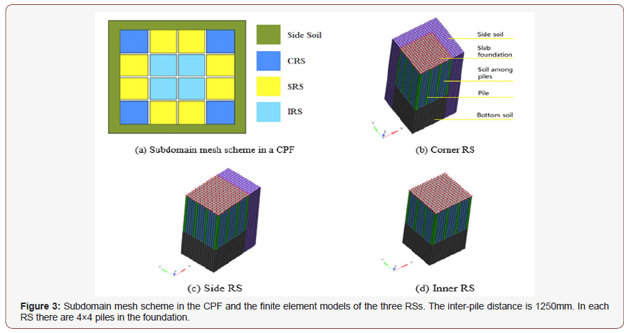
Figure 2 shows the overlap of each RS. It is obvious that the overlap area between neighbor subdomains is contained in both subdomains. In each design, the width of overlap is equal to the diameter of a circular pile or the side length of a square pile. The overlap may exist between two CRSs, or between two SRSs (subdomains 2 and 3 in Figure 1A), or between two IRSs (subdomains 5 and 6 in Figure 1A). It can also be between two neighboring subdomains with different RSs. For example, it could be between subdomains 1 and 2, between subdomains 1 and 4, or between subdomains 4 and 5. Four neighboring subdomains can also have an overlap. According to the definitions of overlap and the width of overlap, there are small square overlaps among four neighboring subdomains such as 1, 2, 4, 5 and 2, 3, 5, 6. The question now is: Why do we set an overlap area between neighboring subdomains? It is obvious that there are many piles in each RS. Initially, the piles are laid out with the same spacing (see Figure 3). Based on this understanding, the advantages of using overlap areas are: (1) the piles layout optimization in each RS is carried out separately. After optimization, the piles in the overlap between two different types of RSs, e.g., subdomains 1 (CRS) and 2 (SRS), may have different lengths in the same position. The final length of a pile in the overlap should be the higher one during assembling the whole CPF. Accordingly, the local stiffness of either subdomain 1 or 2 will be equal or higher than that before assembling. Hence, the settlements of the two subdomains will not become larger after assembling. (2) In deformation analysis of a subdomain, the four vertical sides of a subdomain can be considered symmetric boundaries, which are easily applied when defining loads on the structure.
Optimization models for pile layout
Model 1—Maximal stiffness of CPF
In our analysis, all piles in the foundation initially have the same depth and cross-section size. The pile layout is uniformly distributed along two vertical directions and the distance between any two adjacent piles is the same. In this case, if we want to control the settlement by varying the depths/lengths of piles, the design is a typical topology optimization problem. For example, if the objective is to maximize the stiffness of a CPF subject to both the specified total volume of piles and the uniform settlement of slab, the optimization model can be written mathematically as:
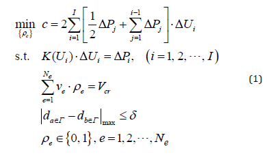
where c is the structural mean compliance, i ΔP and i ΔU are the i-th global incremental load vector and incremental displacement vector, respectively. I is the total number of incremental loads. K is the global stiffness matrix of the whole structure including the CPF, the side soil and bottom soil, at the i-th load case. The stiffness matrix can be calculated using the well-established finite element procedure (Martin and Carey 1973; Qin 2000). vρ and ρe are the volume and relative density of the e-th pile element. If ρρe=1, the e-th pile element exists, if ρe=0, the material in the e-th pile element is replaced with soil, i.e., the pile element becomes a soil element. Vcr is the critical volume of the piles. Γ is the top surface of the CPF. da∈Γ and d b∈Γ are the settlements of the points a and b on Γ . δ is the tolerance of a uniform settlement.
Model 2—Uniform settlement of slab
If we want to minimize the difference in settlement of a slab for a given total volume of piles in the foundation, the optimization model reads:
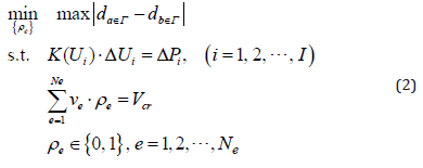
Model 3—Minimize the total volume of piles in foundation
If the aim of the design is to reduce the volume of piles in a CPF, but both the maximal settlement and the uniformity of slab settlement are constrained, the optimization model for pile layout design is written as:
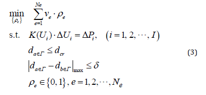
where dcr is the permitted value of the maximal slab settlement.
In Eq.(1), the design variables are the relative densities of the pile elements, and each design variable ( ρe ) has a discrete value: 1 or 0. The optimization problem containing discrete design variables is difficult to solve using the traditional optimization method as the number of pile elements is very large. To apply the topology optimization method to this problem, we relax the relative densities, i.e., ρe∈ [0,1] (e = 1, 2, ¨,N ). To reduce the number of elements with medium density (0 <ρe< 1 ), penalization is applied to the relative density when expressing the relationship between the microstructure and the equivalent elasticity. This method is known as the SIMP (solid isotropic microstructure with penalization) method [17] and is very popular in the continuum topology optimization design field. Briefly, the equivalent modulus of a pile with ρecan be expressed as:

where Ep is the modulus of the solid pile, Es1 is the modulus of the soil among piles. In the present study, p=3 [23].
Flowchart of pile layout optimization
There are four major steps for achieving the optimal pile layout in a CPF:
First, divide the whole foundation into subdomains;
Second, find the optimal pile layouts of each RS;
Third, assemble the whole CPF with the RSs;
Finally, check the design of the whole CPF.
The first step was discussed in section 2. The second step is detailed as follows:
(1) Create the finite element model of the RS (IRS, SRS, and CRS in turn) and initiate parameters of the algorithm, let k=1;
(2) Analyze the structural deformation using the nonlinear finite element method to find the displacement, strain and stress fields;
(3) Calculate the values of objective function and constraint functions, and the values of the first order gradients of the objective function and constraint functions;
(4) Update the design variables (ρe) using a gradient-based optimization algorithm, e.g., method for moving asymptotes (MMA) [24], or second-order cone programming (SOCP) [25];
(5) If Eq. (5) is satisfied or k is equal to a given maximum number of iterations, then go to step (6), otherwise let k=k+1 and go to step (2);
(6) Stop.
The convergent condition in step (5) is

where the tolerance η = 0.05% in this study and the maximum number of iterations is 200. The initial values of the design variables are set to be 1.0. One can also set the values to be 0.5 at start.
The remaining two steps are embedded in section 3.
Parameters and description of conditions
Geometry of CPF: In the CPF shown in Figure 3 there are 4 corner subdomains, 8 side subdomains and 4 inner subdomains. For each group of subdomains there is only one RS. The size of all piles with a square cross-section is 250mm×250mm. The initial length of any one pile is assumed to be 15m. Each pile is discretized into 15 pile elements. The distance between piles (center to center) is 1.25m. The thickness/depth of the slab foundation is 0.3m, and the depth of the bottom soil is 10m. The width and depth of the side soil are 1.5m and 25m, respectively.
Material properties: The shallow foundation consists of an isotropic material with elastic modulus of 2.0×10³ MPa and Poisson’s ratio of 0.3. The material of the piles is also isotropic with elastic modulus of 2.0×10⁴ MPa and Poisson’s ratio of 0.2. The soils are piecewise linear elastic materials. For the side soil, the elastic modulus is 5 MPa and the Poisson’s ratio is 0.35 while the equivalent strain is less than 0.2%. If the equivalent strain is over 0.2%, the elastic modulus of the side soil becomes 1 MPa. The elastic modulus of the bottom soil and soil among piles is 20 MPa (after ground treatment) and the Poisson’s ratio is 0.35 when the compressive strain is less than 0.2%. If the strain is over 0.2%, the modulus is 1 MPa. The material models used in the following tests may differ from the real models of materials, e.g., soils, in practical engineering. But they have no influence on our demonstration of the process of the pile layout design of a CPF [11].
Load: The uniform pressure of 160kPa is applied on the top surface of the shallow foundation. In practical engineering the real loads may be significantly different from this.
Contact state: The side soil and the foundation are in contact and the dynamic friction factor is 0.25 [4,12,26,27].
Manufactured constraint: Along the depth (from top to bottom), the manufactured constraint is applied on the piles during optimization to maintain continuity of piles.
Optimizer: The topology optimization of a RS is carried out by Hyperworks (commercial software).
Design domain: All the pile elements are in the design domain. The soil elements are in the non-design domain.
Settlement uniform: The maximum difference in the settlement of the top surface of the slab is no more than 0.1% of the span of the foundation. The settlement of slab in each RS is confined within (55, 60) mm (Figure 3).
Pile layout design of a CPF with fixed pile-mesh scheme in RSs
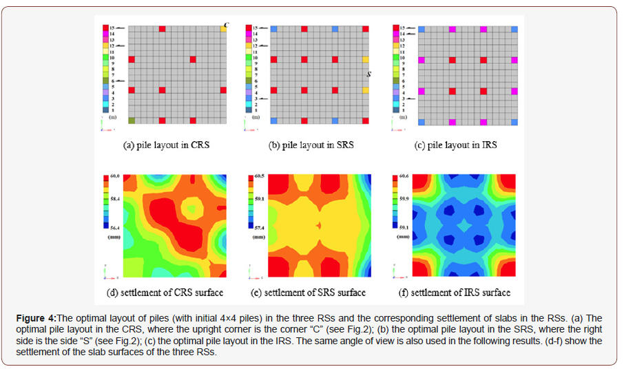
Optimal pile layouts in each RS
(Figure 4)
In Figure 4A, the final optimal piles with different lengths in the CRS are shown. There are only 10 piles. Compared with the original (4×4=)16-pile layout, the present layout of piles has neither uniform inter-pile distance nor uniform depth. In detail, the length of the pile at the corner “C” is 12m. The pile at the lower left corner is 6m in length. The remaining two corners have no pile (the lengths of those two piles are set at zero in the calculation). Of the remaining 8 piles, the longest is 15m. On the symmetry axis of the CRS foundation (the diagonal line from the lower left corner to upper right corner) there are four piles. On the other diagonal line there is no pile. Supported by the 10 piles, the settlement of the slab is controlled within [56.4, 60.0] mm (see Figure 4D).
In Figure 4B, the final piles in the SRS are given. There are 16 piles with three different lengths: 3m, 12m and 15m. On the side “S”, the two piles at the corners have the same length of 15m, and the two intermediate piles have the same length of 12m. Due to the symmetry of the subdomain, there are four piles with length of 3m on the upper and lower sides. They are in the overlap area between the CRS and the SRS. The remaining 8 piles are 15m in length. On the left side are four piles with different lengths. They are in the overlap area between the SRS and IRS. Supported by the piles shown in Fig.4b, the settlement of the slab in the subdomain is controlled within [57.4, 60.5] mm (see Figure 4E). There are 16 piles with three different lengths in the final IRS (see Figure 4c). The four shortest piles with the length of 3m are at the four corners, and four long piles with the length of 14m are in the overlap area. The remaining 4 piles in the central area are 15m in length. In Figure 4F, the settlement of the slab is within (59.1, 60.6) mm when supported by the piles shown in Figure 4C. All the piles in Figure 4 (A-C) are solid piles, i.e., the pseudo-densities of the pile elements are equal to 1.0, but they have different lengths. When the length/depth of a pile is 3m, it implies that only 3 solid pile elements connected with slab remain in the final layout. The other 12 pile elements have changed into soil elements [28,29].
Assembly of pile layout in the whole CPF
Assembly Criterion: In assembly of the final pile layout into the whole foundation, the length of the pile in the overlap area is equal to the longest among the values of the piles in the neighboring RSs. For example, the lower side of the CRS in Figure 4A is the boundary of the overlap between the CRS and SRS. The upper side of the SRS in Figure 4B is the other boundary of the same overlap. According to the criterion stated above, the lengths of the four piles from left to right are 6m, 15m, 15m, and 15m, respectively. These lengths are determined by the piles’ lengths in CRS, CRS, CRS, and SRS, respectively. Similarly, if the overlap is between an upper SRS and a lower SRS, the lengths of the piles in the overlap area remain unchanged. If the overlap is between the left side of an SRS and the right side of an IRS, the lengths of the piles from upper to lower are 3m, 15m, 15m, and 3m, respectively. All these lengths are determined by the length of the relevant piles in the SRS. In particular, the lower left corner of a CRS, the upper left corner of an SRS, and the upper right corner of an IRS may be in the same overlap area. The length of the pile in the overlap is determined by that of the pile in the CRS. In this case, it is 6m.
In accordance with the assembly criterion, the final pile layout in the whole foundation is shown in Figure 5A. The initial number of piles in the whole CPF is 169. After optimization, there are only 153 piles with 5 different lengths, 3m, 6m, 12m, 14m, and 15m, respectively. It is noted that there are three special characteristics of the resulting CPF. First, the layout of the piles in the final design is non-uniform. That implies that a non-uniform pile layout can be obtained by topology optimization based on the initial uniform pile layout design. Secondly, the depths of the piles are different. That means that an initial CPF with uniform pile length can be changed into a CPF with both longer and shorter piles. Thirdly, the number of pile depths is not great. In the present example, there are only 5 types of pile. Therefore, the process of constructing the CPF is not complex, as shown in the results in Figure 5A (Figure 5).
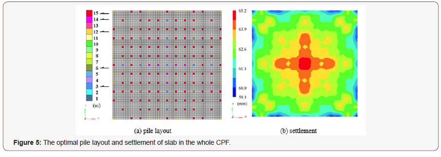
Figure 5B presents the normal displacement along the depth of piles of the slab in the CPF, showing that the settlement is within (59.3, 65.2) mm. Clearly, that interval is different from (55, 60) mm, which was used in finding the final pile layout in the three RSs. The maximum settlement difference is 5.9 mm, which is about 0.47% of the inter-pile distance or 0.039% of the side length of foundation (15.25m). It is concluded that uniform settlement of the slab of a foundation can be controlled accurately by the subdomain method.
Effects of inter-pile distance
Models and parameters
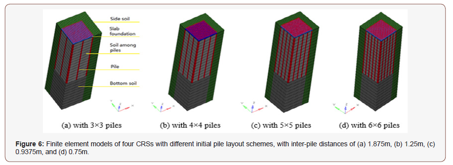
In the analysis in section 3.2, we arrived at the final pile layout in the CPF by assembling RSs with 4×4 piles. If the initial pile layout in each RS is not 4×4, i.e., the inter-pile distance varies, can we find a better pile layout in the same CPF? To answer this question, four different pile-mesh schemes in a RS are considered. The initial pile layout schemes are 3×3, 4×4, 5×5, and 6×6. Figure 6 shows the finite element models of the four CRSs. Their related SRSs and IRSs are similar to those given in Figure 3. On the other hand, the Poisson’s ratio of materials can influence the stress states. Hence, the effect of Poisson’s ratio is studied in this section. All the parameters except the Poisson’s ratios of soils are the same as those used in section 4.1. In this section, the Poisson’s ratio of the side soil is 0.45 (when the soil is well-rolled compactly). The bottom soil and the soil among piles have the Poisson’s ratio of 0.4 (Figure 6).
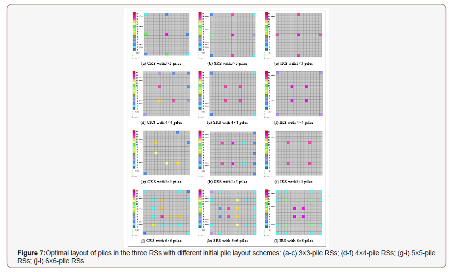
Optimal pile layout in each initial RS
(Figure 7)
Final pile layout in the CPF and settlement
The settlement uniformity of the foundation is defined as the ratio of maximum settlement difference over the pile distance. From both Figure 8 &Table 1, we find that the final design of pile layout in the CPF depends on the inter-pile distance/initial pile scheme. For example, if we use a 3×3 scheme, the final pile volume is 40m3, which is the lowest one among the four schemes. However, the maximum settlement of the slab, 70.4mm, is the greatest among the four cases. Even with the maximum settlement difference of 7.3mm, at the greatest inter-pile distance, the settlement uniformity is the best among the four cases. In the final design, the number of piles is 76, with 5 different lengths. We also find that a foundation with highest inter-pile distance would have the smallest pile volume, lowest number of piles and lowest settlement uniformity. However, it would have the highest maximum settlement difference. From an engineering point of view, the 4×4 or 5×5 schemes have better comprehensive performance. For example, the final pile volume in either of those schemes is less than that of the 6×6 scheme. The final pile number and the number of lengths are not very high, which simplifies the construction of the CPF easier. The maximum settlement is also not very high in this case.
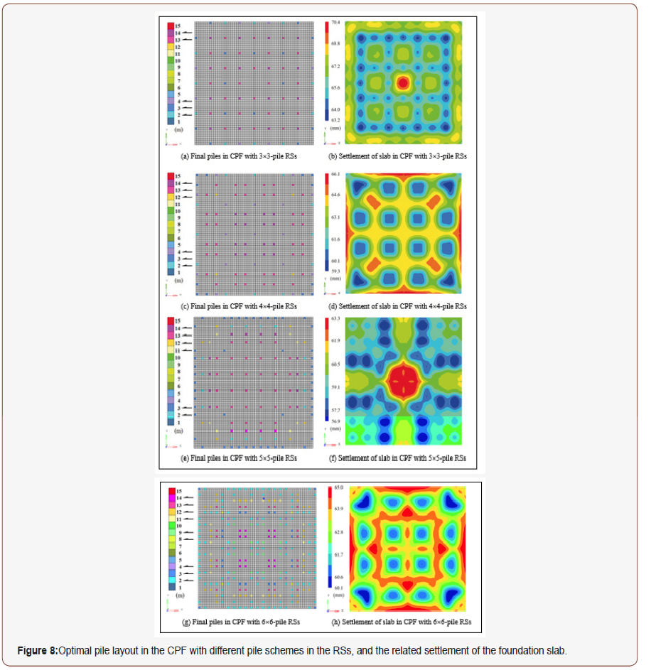
Table 1:Comparison of results from four designs of CPF with different pile schemes in RSs.

Discussion and Conclusion
In the optimization of pile layout in a CPF, the major challenge is the high computational cost when material nonlinearity and state nonlinearity are involved, and the number of piles is too great. To provide a feasible design for pile layout in a CPF with better settlement uniformity and lower pile volume, a subdomain method is proposed. The validity of the method is verified by some numerical tests. From the results and analyses obtained, the following conclusions are drawn:
1. Using the subdomain method, only a few subdomains such as RSs are used to carry out topology optimization for finding the lengths of piles. Assembling the final pile layout in the whole foundation can be achieved by assembling the RSs. Hence, the height size of a foundation will have only a slight influence on the algorithm efficiency.
2. When the initial piles in the foundation have the same length and the same inter-pile distance, some piles will be deleted (by setting the pile length to zero) after topology optimization, and the lengths of the remaining piles are not identical. Hence, the final CPF becomes a foundation with a
3. A higher inter-pile distance in the foundation leads to a smaller final pile volume but higher maximum settlement.
4. A higher inter-pile distance also leads to fewer piles in the foundation, which in turn makes the construction of the foundation easier.
Acknowledgement
None.
Conflict of Interest
No conflict of interest.
References
- Gong X (1992) Composite foundation Zhejiang University Press, Hangzhou, China.
- Gong XN (2007) Generalized composite foundation theory and engineering application. Yantu Gongcheng Xuebao(Chinese Journal of Geotechnical Engineering) 29(1): 1-13.
- Wang MS, Wang GC, Yan XF, Tong JX, Yan ML (2005) In-situ tests on bearing behavior of multi-type-pile composite subgrade. Yantu Gongcheng Xuebao(Chinese Journal of Geotechnical Engineering) 27(10): 1142-1146.
- Tamura S, Adachi K, Sakamoto T, Hida T, Hayashi Y (2012) Effects of existing piles on lateral resistance of new piles. Soils and Foundations 52(3): 381-392.
- Bao X, Morikawa Y, Kondo Y, Nakamura K, Zhang F (2012) Shaking table test on reinforcement effect of partial ground improvement for group-pile foundation and its numericalsimulation. Soils and Foundations 52(6): 1043-1061.
- Suzuki H, Tokimatsu K, Tabata K (2014) Factors affecting stress distribution of a 3× 3 pile group in dry sand based on three-dimensional large shaking table tests. Soils and Foundations 54(4): 699-712.
- Gotman A, Khurmatullin M (2012) Performance of piles installed by jet-grouting method in clayey soils. Soil Mechanics and Foundation Engineering 49(4): 139-143.
- Ge X, Gong X, Zhang X (2003) FEM analysis and design of long-short-pile composite foundation. Journal of Building Structures 24(4): 91-96.
- Shahin MA (2014) Load–settlement modeling of axially loaded steel driven piles using CPT-based recurrent neural networks. Soils and Foundations 54(3): 515-522.
- Hariri-Ardebili M (2014) Impact of foundation nonlinearity on the crack propagation of high concrete dams. Soil Mechanics and Foundation Engineering 51(2): 72-82.
- Zhou H, Liu H, Kong G (2014) Elastic Analysis of a Pile Rectangular Cross Section Under Lateral Load. Soil Mechanics and Foundation Engineering 51(3): 126-131.
- Rose A, Taylor R, El Naggar M (2013) Numerical modelling of perimeter pile groups in clay. Canadian Geotechnical Journal 50(3): 250-258.
- Isobe K, Kimura M, Ohtsuka S (2014) Design approach to a method for reinforcing existing caisson foundations using steel pipe sheet piles. Soils and Foundations 54(2): 141-154.
- Gotman A (2013) Performance of combined pile foundations under a horizontal load. Soil Mechanics & Foundation Engineering 50(3): 85-91.
- Randolph M (1992) Design methods for pile groups and piled rafts. XIII ICSMFE, pp.61-82.
- Bendsøe MP, Kikuchi N (1988) Generating optimal topologies in structural design using a homogenization method. Computer Methods in Applied Mechanics and Engineering 71(2): 197-224.
- Zhou M, Rozvany G (1991) The COC algorithm, Part II: topological, geometrical and generalized shape optimization. Computer Methods in Applied Mechanics and Engineering 89(1): 309-336.
- Xie Y, Steven GP (1993) A simple evolutionary procedure for structural optimization. Computers & Structures 49(5): 885-896.
- Qin QH, He XQ (1995) Variational principles, FE and MPT for analysis of non-linear impact-contact problems. Computer Methods in Applied Mechanics and Engineering 122(3): 205-222.
- Wang MY, Wang X, Guo D (2003) A level set method for structural topology optimization. Computer Methods in Applied Mechanics and Engineering 192(1): 227-246.
- Sheng X, Qiu B (1995) Topological optimization of the space pile foundation. Journal of Changsha Railway University 13(4): 25-32.
- Chan C, Zhang L, Ng J (2009) Optimization of pile groups using hybrid genetic algorithms. J Geotech Geoenviron Eng 135(4): 497-505.
- Bendsøe MP, Sigmund O (1999) Material interpolation schemes in topology optimization. Archive of Applied Mechanics 69(9-10): 635-654.
- Svanberg K (1987) The method of moving asymptotes—a new method for structural optimization. International Journal for Numerical Methods in Engineering 24(2): 359-373.
- Alizadeh F, Goldfarb D (2003) Second-order cone programming. Mathematical Programming 95(1): 3-51.
- Fayyazi MS, Taiebat M, Finn WL (2014) Group reduction factors for analysis of laterally loaded pile groups. Canadian Geotechnical Journal 51(7): 758-769.
- Zheng G, Peng SY, Ng CW, Diao Y (2012) Excavation effects on pile behaviour and capacity. Canadian Geotechnical Journal 49(12): 1347-1356.
- Martin HC, Carey GF (1973) Introduction to Finite Element Analysis: Theory and Applications. McGraw-Hill Book Company, New York, USA.
- Qin QH (2000) The Trefftz finite and boundary element method. WIT Press, Southampton, UK.
-
Kun Cai, Jiao Shi, Pengfei Wang. Subdomain Method for Layout Optimization of Piles in a Composite Pile Foundation. Cur Trends Civil & Struct Eng. 4(1): 2019. CTCSE.MS.ID.000576.
-
Composite foundation, Topology optimization, Pile foundation, Subdomain method, Settlement, Composite pile foundation, Mapping, Pile foundations
-

This work is licensed under a Creative Commons Attribution-NonCommercial 4.0 International License.


