 Review Article
Seismic Response of Concrete Components and Systems Reinforced with Fiber Reinforced Polymer (FRP) Bars: Trend and Challenges
Ahmed Arafa, Department of Civil Engineering, University of Sohag, Egypt, Email:ahmed_arafa@eng.sohag.edu.eg
Received Date: August 06, 2019; Published Date: August 13, 2019
Abstract
The deterioration of reinforced concrete structures due to steel corrosion has become a serious problem in the last decades. In North America, many vital structures such as bridges and parking garages are suffering from this phenomenon and millions of dollars are annually spent in repairing and rehabilitation and in some cases the complete replacement of structures. In the last three decades, the use of fiber reinforced polymers (FRPs) as alternative reinforcing bars has emanated as a viable solution for the corrosion problems and found their way into applications in different structural elements. The promising results made it is possible for building a complete structure entirely reinforced with FRP bars; starting from the base to the roof. However, since all focus in experiments was given to the resistance under static load, the feasibility of of such structures in region prone to earthquake has become questionable. Given this call, many experimental investigations have been conducted around the world covering the response of FRP-reinforced shear walls and structural frames. Many design aspects have been introduced; however, more important issues are still ambiguous. This paper attempted to provide up-to-date knowledge related to the research work pertaining to the seismic response of concrete components and systems reinforced FRP Bars. The paper also identifies the challenges and future opportunities for the broad use of these advanced systems in civil engineering and construction.
Keywords: GFRP bars; Reinforced concrete; Frames; Walls; Hysteretic response; Energy dissipation
Introduction
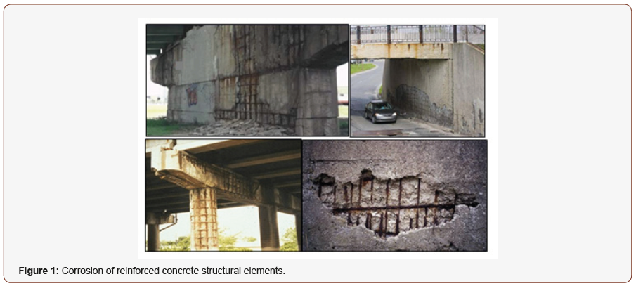
Thousands of bridges and parking garages in North America need repair and rehabilitation, or complete replacement because of corrosion problems (Figure 1). Some conditions, such as, significant temperature fluctuations and environmental aggression aggravate this phenomenon and make the hazard more severe. The high economic consequences of corrosion problems led engineers all over the world to search for new and affordable construction materials as well as innovative approaches and systems to problem solving. In recent years, the use of fiber-reinforced polymer (FRP) as an alternative reinforcing material in concrete structures has emerged as an innovative solution to overcome the corrosion problem. In addition to its non-corrodible nature, FRP reinforcement presents many advantages such as high strength-to-weight ratio, ease of handling, and immunity against the electrochemical corrosion [1-3]. These advantages paved the way for their applications into numerous construction elements such as slabs, beams, columns, and recently precast bridges [4-7].
In recent years and with the requirement of designing a multistory building with adequate strength and stiffness using FRP reinforcement, research has been diverted to the feasibility of using lateral resisting elements that reinforced with FRP bars in region prone to earthquake. Many issues have been investigated; however, some critical issues and challenges remain. The presented study aimed at providing the up-to-date knowledge and concludes by briefly summarizing future challenges facing reinforced FRPreinforced constructions under seismic loads and possible solutions through collaborative and individual research efforts.
Frp Rc Structural Systems for Seismic Forces
Structural frame systems
Moment-resisting frames are rectilinear assemblages of beams and columns that are well detailed in a standard way to be able to resist gravity and seismic loads. The philosophy behind the seismic design of frame systems is to provide them with sufficient ductility by which they can dissipate the acting seismic energy. However, unlike steel; since FRP bars behave linearly up to failure without any ductility, the feasibility of structural elements solely reinforced with FRP in area prone to earthquake has become questionable. To address this issue, many investigations have been conducted to validate the feasibility of FRP RC frame in earthquake regions. A brief summary for the implemented works, ordered chronologically, is given as following. The first investigation was conducted by Fukuyama et al. [8] on a half-scale three-story concrete frame totally reinforced with braided aramid fiber polymer reinforcing bars. The frame had 1800 mm story height, and 3500 mm span (between column centers). The selected reinforcement ratios for the beams were 0.64% and 0.48% at the bottom and top; respectively. Meanwhile, the main reinforcement ratio of the columns was 1.47%. The specimen was tested under reversed cyclic loading applied at the mid-height of the third floor up to failure. It was shown that the frame remained elastic up to a drift angle of 1/50 rad, and no substantial decrease in strength took place after rupture of some main beam bars due to the high degree of indeterminacy of the frame.
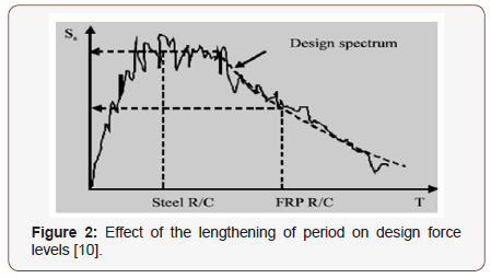
Due to the elastic nature of FRP bars in tension, the unloading branch of hysteresis loops was observed to aim towards the origin with negligible residual deformations. This indicated that rehabilitation of FRP RC frame would be much easier than the case if it was reinforced with steel. Said & Nehdi [9] tested two full-scale beam-column joint specimens; one reinforced with steel while the other with GFRP grids in order to investigate their performance under the event of an earthquake. Beams and columns cross sections were identical and measured 250 × 400 mm. The GFRP RC specimen was designed to have a similar flexural capacity to that of the reference steel RC specimen, thus inducing a comparable level of joint shear input. The GFRP RC specimen showed a satisfactory drift capacity, assuming a minimum drift requirement of 3% as recommended in the literature for ductile frame buildings. However, the joint showed very low plasticity features resulting in lower energy dissipation compared to that of the conventional steel RC beam-column joint. Sharbatdar & Saatcioglu [10] conducted an experimental program including testing two types of reinforced concrete elements; square columns and rectangular beams. The elements represented portions of column and beam elements between rigidly attached adjoining members and the points of contra-flexure, as cantilever specimens. Four specimens of each element were constructed and reinforced with Carbon FRP (CFRP) bars and CFRP grids as longitudinal and transverse reinforcement, respectively. The studied parameters were the shear span length and the spacing of transverse reinforcement. The columns were tested under constant axial load and lateral cyclic load while the beams were tested under cyclic load only. The test results indicated that CFRP RC concrete beams and columns can attain a lateral drift ratio up to 3%, while essentially remaining elastic in spite of the softening induced by cracking. It was concluded that using CFRP as flexural and shear reinforcement in concrete frames is feasible. Given the elastic nature of CFRP bars; however, it was suggested that CFRP RC frames should be designed based on elastic member behavior (i.e. the seismic reduction factor is equal to the unity) while taking advantage of relative flexibility of FRP material and the associated elongations in the fundamental period of structures with potentially reduced seismic demand (Figure 2).
Hasaballa et al. [11] tested four full-scale exterior T-shaped beam-column joints. The first specimen was reinforced with longitudinal and transverse steel bars and served as a reference specimen. The second was similar to the first; however, GFRP bars were used in the longitudinal direction. The rest two specimens were reinforced with GFRP bars and stirrups with different reinforcement ratio. Each specimen simulated a beam-column connection of an exterior bay in a multi-bay, multistory reinforced concrete moment-resisting plane frame. It was concluded that although steel RC specimen was able to dissipate energy in the order of 2 to 3 times that of the GFRP specimens, the residual strains in the GFRP flexural reinforcement at the 4.0% drift ratio were much lower than in steel RC specimen. This indicated that the joint will regain its original shape after removing the loads, thus requiring repair is minimal. Continuing their efforts in studying the seismic performance of FRP- RC joints, another investigation was conducted in the University of Manitoba by Mady et al. [12]. A total of five full-scale beam-column joint prototypes were constructed and tested under cyclic loading up to failure. The first test specimen was reinforced with conventional steel bars and stirrups and served as a control specimen. The second specimen was reinforced with GFRP bars and steel stirrups. The remaining three specimens were solely reinforced with GFRP bars and stirrups with different reinforcement ratios. The findings revealed that GFRP RC joints can be designed to satisfy both strength and deformability requirements. The tested GFRP RC concrete beam-column joints safely achieved 4.0% drift capacity with insignificant damage. The obtained drift capacities were more than the 2.5% required by the NBCC [13] and the 3.5% required by the ACI 374.1 [14]. The results also demonstrated that increasing the beam reinforcement ratio can enhance the ability of the joint to dissipate the seismic energy through utilizing the inelastic behavior of concrete as long as the joint is safe under the applied shear stresses. Tavassoli et al. [15] tested nine circular columns under constant axial load and lateral cyclic displacement excursions cyclic loading. The axial load was either 0.28Po or 0.42Po, where Po is the nominal axial load capacity of the column. Two type of GFRP provided by two manufacturers tested as internal and transverse reinforcement. The diameter of spiral was either 12 mm or 16 mm and spaced at a distance ranged from 50 mm to 275 mm. Experimental results in the form of moment-versus-curvature and shear-versus-tip deflection hysteretic responses and various ductility parameters were presented and compared with results of similar steel RC circular columns in other investigation [16]. The results showed that concrete columns reinforced with GFRP bars and spirals can behave in a manner that has stable post-peak response and achieve high levels of deformability. The results also indicated that due to the large stiffness of GFRP bars than steel beyond yielding, GFRP RC columns performed in a more stable manner than the companion steel RC specimens.
The promising test results promoted development in FRP bars manufacturing and yielded other generations with enhanced performance. This was patently evident from the conducted test results beyond 2015. In 2016, Ali & El-Salakawy [17] tested eight full-scale GFRP RC column prototypes with variable longitudinal reinforcement ratios, level of axial load, and stirrup spacing. The reported drift capacity at failure ranged between 8.5 and 12.5%, which highly exceeds the limitations of North American building codes. Additionally, it was reported that well-confined columns can behave plateau with gradual damage before failure which intern provide wide warning before failure. Naqvi & El-Salakawy [18] studied the effect of using lap splices in GFRP-RC rectangular columns. The experimental program comprised six specimens; five reinforced with GFRP bars while the last specimen reinforced with steel and served as a reference. The test parameters included lap splice length of longitudinal reinforcement and transverse reinforcement spacing. Test results indicated that a splice length of 60 times the diameter of the longitudinal column bar was adequate in transferring the full bond forces along the splice length. In addition, lap-spliced GFRP-RC columns with closely spaced transverse reinforcement showed stable hysteresis response and achieved high levels of deformability, which far exceeded the limitations of the North American building codes.
Shear walls
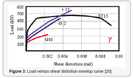
Shear walls are broadly used as the first line of defense against earthquake excitations and they have many advantages over moment-resisting frames. Compared to the studies conducted in FRP RC resisting frames; however, very little research has been gone toward the feasibility of shear walls reinforced with FRP bars in regions prone to earthquake excitations. The first attempt was conducted by Yamakawa & Fujisaki [19] on seven wall specimens reinforced with CFRP grids. The specimens were tested under reversed cyclic lateral loading while simultaneously subjected to constant axial load. All specimens exhibited early degradation in lateral load capacity when 1% drift was achieved associated with low energy dissipation. The authors attributed the poor performance to three main reasons: (1) the CFRP grids were not able to carry compressive stress and therefore experienced fracture under low compressive stresses, (2) there was a need to design adequate development length to prevent the reinforcing bars from pulling out of the wall base, and (3) the CFRP grid reinforcement did not provide concrete confinement. 20 years later, a comprehensive research program that includes investigating the response of shear walls totally reinforced with GFRP bars under simulated seismic loading have been implemented at the Canadian Foundation for Innovation (CFI) Structural Laboratory in the Department of Civil Engineering at the University of Sherbrooke, Sherbrooke, QC, Canada. The program commenced by Mohamed et al. [20] through testing four large-scale shear walls—one reinforced with steel bars (as reference specimen) and three totally reinforced with GFRP bars—were constructed and tested to failure under quasi-static reversed cyclic lateral loading. The specimens represented mid-rise walls (aspect ratio = height/length = 2.0 → 4.0) that commonly used in parking garages. From the learned lessons in Yamakawa and Fujisaki study [19], the authors strove to avoid all brittle failures that might occur in shear walls and that would prevent them from reaching their capacities. The main parameter was the wall’s aspect ratio; the three GFRP RC walls (G10, G12, and G15) had aspect ratio of 3.5, 2.9 and 2.3, respectively. The steel specimen ST15 served as a reference for G15, hence it had the same concrete dimensions and axial stiffness. The reported test results clearly showed that properly designed and detailed GFRP RC walls could reach their flexural capacities with no strength degradation, and that shear, sliding shear, and anchorage failures were not major problems and could be effectively controlled. It was also reported that GFRP RC walls showed a recoverable and self-centering behavior up to allowable drift limits before moderate damage occurred and achieved a maximum drift level meeting the limitation of most building codes. The experimental results of the test specimens were then used to investigate the interaction of flexural and shear deformations [21]. It was found that, at early stage of loading, flexural deformations dominated the response. At higher levels of lateral drift; however, the shear deformations become relatively pronounced, although the factored shear strength is 30% higher than the ultimate flexural lateral capacity of the shear walls. The results also showed that using GFRP bars better controlled shear distortion relatively to the case of using the convectional steel. The steel RC wall, especially after yielding of the vertical bars, experienced nearly twice as much distortion as the companion specimen reinforced with GFRP (Figure 3).
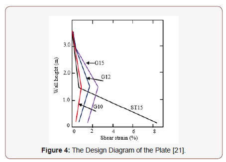
The authors explained that due to the elastic nature of GFRP bars, shear strain was uniformly distributed along the walls height, resulting in control shear deformations than those experienced in steel RC shear wall in which yielding of steel bars intensified the shear strains at the yielding location as shown in (Figure 4).
In an attempt for introducing preliminary guidelines that organize using GFRP-reinforced walls, three aspects were investigated that is: 1) estimate elastic and maximum allowable deformation; 2) propose values for force modification factors; 3) define and estimate plastic hinge length for GFRP-reinforced walls [22]. As a base line for the three aspects the bilinear idealized load-displacement response was defined based on the observed behavior of the tested walls. It was stated that for steel-reinforced shear walls, the elastic region ended at the yield-deformation point Δy and the inelastic region at the maximum deformation point Δu (Figure 5A). On the other hand, for GFRP-reinforced shear walls, the elastic region ended at the start of concrete inelasticity (Δe) — that is, concrete deterioration at the compressed end of the wall (corresponding to a concrete compressive strain equal to 0.003) -and the inelastic region at the maximum deformation point (Δu). The major difference between the steel- and GFRP- reinforced shear walls is the absence of yielding phenomenon in GFRP bars. For this reason, the transition point between the elastic and inelastic regions in GFRP-reinforced shear walls was defined as virtual yield deformation point (Δe). Accordingly, producing the bilinear idealized curve meant that two deformation points had to be welldefined for each wall specimen: Δy or Δe and Δu (Figures 5A, 5B).
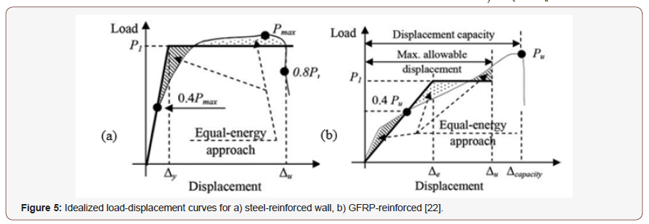
Based on this assumption it was concluded the following points:
1. The force modification factors Rd and Ro were suggested to be taken as 1.5 and 1.3, respectively, for the GFRPreinforced shear walls;
2. The virtual plastic-hinge length in the GFRP-reinforced shear walls could be estimated and was found to be equal to 0.5lw and lw (where lw is the wall length) for the lower and upper limits, which is similar to steel-reinforced shear walls;
3. The rotational capacity must not be less than 1.5% and the maximum suggested limit is 2.5%.
4. A minimum value of 0.4% for rotational demand must be provided to ensure a minimum level of deformability for GFRP-reinforced shear walls.
The promising results conducted by Mohamed et al. [21] promoted a new study that investigate the impact of increasing the confinement level in the boundaries and its effect on inelastic deformation capacity. Hassanein et al. [23] constructed and tested five concrete shear walls reinforced with GFRP bars and spirals under reversed cyclic quasi-static loading and constant axial load. The main difference between the walls was the GFRP reinforcement configuration in the boundary elements. Two shear walls included boundaries reinforced with square GFRP spirals, while the third shear wall had boundaries reinforced with circular GFRP spirals. The remaining two shear walls had higher confinement of boundary elements consisting of square GFRP spiral embedded inside rectangular GFRP spiral in one and rectangular GFRP spiral with two GFRP ties in the other (Figure 6).
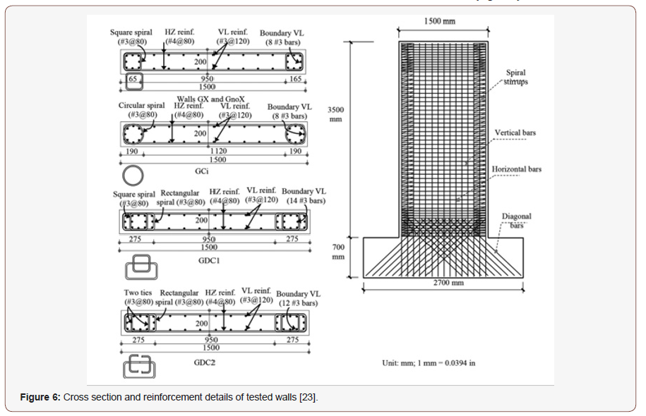
The walls with higher confinement clearly achieved higher drift ratios and strength. The ductility force modification factor was evaluated based on the idealized curve and found to range from 2.4 to 2.9. A conservative value of Rd = 2.4 was recommended. A large proportion of the walls constructed in the North America can be classified as squat walls with wall height-to-length (aspect ratios) typically less than 2.0. Such wall category is commonly used in lowrise buildings such as nuclear plants, industrial buildings, parking structures, highway overpasses, and bridge abutments. Given the widespread usage of such wall category and their exposure to deterioration induced by steel corrosion, assessment the feasibility of using FRP bars as internal reinforcement was necessary. Under this call, an experimental and analytical investigation titled “assessment strength, stiffness, and deformation capacity of squat walls reinforced with GFRP bars” has been launched [24-28]. The study included testing nine large-scale squat walls with aspect ratio (height-to-length ratio) of 1.33-one reinforced with steel bars (as reference specimen) and eight totally reinforced with GFRP bars. The specimens were tested under reversed cyclic loading without axial load, because the intent was to study sliding resistance provided by GFRP bars while conservatively omitting the effect of axial load. The key studied parameters were: (1) use of bidiagonal web reinforcement; (2) use of bidiagonal sliding reinforcement; and (3) web reinforcement configuration (horizontal and/or vertical) and ratio. Despite the steel-reinforced wall (S4-80) and its companion GFRP-reinforced wall (G4-80) had the same reinforcement ratios and configurations, S4-80 exhibited extensive sliding shear deformations, while G4-80 failed in flexural compression and almost the full flexural capacity for the confined section was achieved. It was reported that in S4-80, a major continuous crack along the wall length formed above the sliding reinforcement and remained open even under compressive reversal loading because the longitudinal reinforcement yielded. The shear stress was therefore transferred along this crack primarily by longitudinal reinforcement dowel action, because the friction-resistance forces maintained by aggregate interlock were degraded under cycling. Because of the relatively flexible nature of this mechanism, the sliding-shear deformations localized in this zone and caused concrete deterioration with subsequent degradation of lateralloading capacity before the full flexural capacity was achieved. On the other hand, in G4-80, the elastic nature of GFRP bars helped the cracks to realign and close between load reversals and spread deformations along the wall height rather than localizing them in the plastic-hinge zone. Thus, the specimen could achieve its flexural capacity with no sign of sliding distress. The results revealed that G4-80 achieved an ultimate load and drift capacity higher than S4- 80, with ratios equal to 71% and 50%, respectively.
While G4 (without bidiagonal sliding reinforcement) was expected to fail due to sliding-shear, it did so identically to G4-80 (gradual flexural compression), while the sliding displacement was negligible. This indicated that the assumption “the shear resistance along unintentionally roughened shear plane is equal to the transverse shear strength of the crossing reinforcement at right angles” [29] is not completely valid for GFRP-reinforced squat walls. Hence, this suggests that the mechanism of aggregate interlock in the flexural compression zone could be engaged with the dowel action to resist the applied shear stresses as the flexural cracks that formed between the wall and the base tended to realign and lock up in the compression zone with load reversal due to the elastic nature of the GFRP bars. Bidiagonal web reinforcement has been shown to be more effective than conventional web (horizontal and vertical) reinforcement in controlling shear-induced crack widths. It was explained that the diagonal web reinforcement was almost perpendicular to the shear-crack direction, so it acted primarily in direct tension, while the horizontal and vertical web reinforcement intersected the shear cracks at 30° to 60°, so it tended to act essentially as dowels. The test results, however, revealed that diagonal bars exposed to out-of-plane buckling at last stage of loading associated with unrepairable damage and strength degradation. To avoid this phenomenon, it was suggested adding transverse links, or prestressing the diagonal grid. Different failure modes (flexural compression, flexural rupture, and diagonal tension failure) have been observed as function of horizontal and vertical web reinforcement configurations (horizontal and/or vertical) and ratios. The horizontal web reinforcement was found to significantly increase the ultimate strength as long as the failure was dominated by diagonal tension but had no significant effect if in excess of what was needed for flexural resistance. Both horizontal and vertical web reinforcement was shown to be essential for crack recovery between load reversals and for controlling shear-crack width as well as for enhancing the concrete contribution to the lateral shear resistance. Documentation of the strain distribution in either horizontal or vertical direction was also presented. The results showed confirmed the finding conducted by Mohamed et al. [22] that is using GFRP bars distributed strain and deformation along the wall height that in turn-controlled damage (Figure 7).
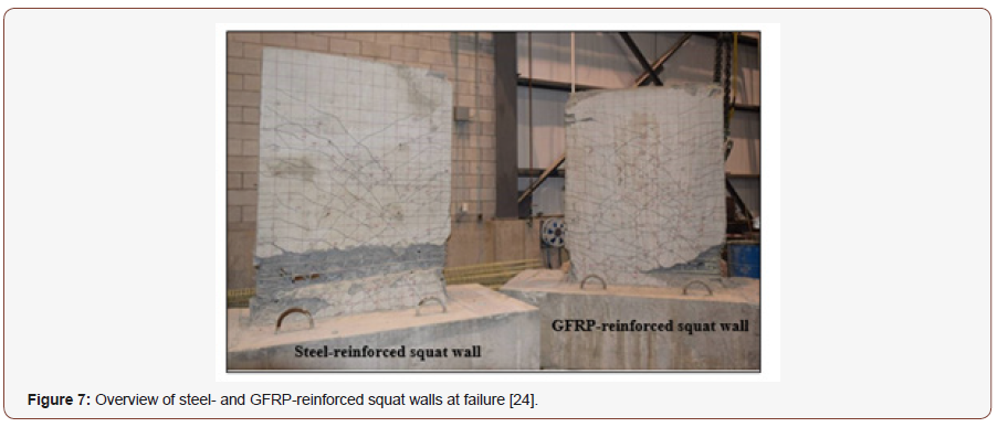
The test results were then served as threshold for developing a proposal for predicting the strength of GFRP-reinforced squat walls. The prediction process applied philosophies similar to those used in CSA A23.3 [29] and ACI 318 [30] for steel-reinforced squat walls with some modifications to account for the differences in the mechanical properties between FRP and steel bars. Some critical issues have been highlighted and recommendations have been delivered to attain an accurate estimation for ultimate strength as follows:
1. The shear estimation method adopted by ACI 440.1R [31] yielded a conservative estimation of the ultimate shear strength. An accurate estimation of the concrete shear contribution to account for the increase after the first shear crack and modifying the assumption of a 45° shearcrack angle adapted for walls with different properties might, however, be necessary.
2. The shear method in CSA S806 [32] was shown to predict closely the shear-crack angle. Nevertheless, the method underestimated ultimate shear strength because of neglecting the concrete’s contribution to shear strength, which could lead to reinforcement congestion. Therefore, the ultimate shear strength was recalculated using the concrete shear strength based on the Razaqpur & Isgor [33] equation, which yielded more reasonable yet conservative estimations.
3. The reinforcement detailing in the boundary-improved concrete confinement, improving the predicted ultimate strength. Therefore, the confinement effect should be considered in the design.
Given their importance in evaluate the lateral displacement, both flexural and shear stiffness of the tested walls were estimated. The study yielded to the following findings:
1. Decoupling flexural and shear deformation without considering curvature variation can lead to overestimated deformation, while correcting the deformations based on the estimated center of rotation produced consistent results.
2. Shear deformation contributed significantly to the total deformation and cannot be omitted, even if the shear strength is greater than the applied load.
3. The cracked shear stiffness of GFRP RC concrete squat walls can be estimated based on the truss model with an acceptable level of conservatism. To ensure this conservatism, the shear-crack angle should be estimated based on CSA S806-12 and the concrete shear strength is recommended to be equal to 0.12 bw lw fc’0.5.
4. In calculating flexural deformation and the consequent normalized flexural stiffness, both ACI440.1R-15 [31] and CSA S806-12 [32] yielded results in good agreement with the experimental results, although CSA S806-12 [32] appears to be more conservative.
5. Within the context of displacement-based design method, a simple model that correlates the flexural and shear stiffness degradation of the test walls to their drift was proposed (Eq. 1, 2).

where Ks is the secant shear stiffness at a lateral top drift equal to δ; Kse is the elastic shear stiffness; ρ is the horizontal web reinforcement ratio.

where Kf is the secant flexural stiffness at a lateral top drift equal to δ; Kfe is the elastic flexural stiffness.
Discussion and Conclusion
The presented results are promising and constituted a step toward using FRP reinforcement in a lateral-resisting-systems. In spite of many aspects have been investigated, some issues the effect of some crucial parameters are still ambiguous. A brief summary for these aspects can be presented as follows:
1. All focus in frame elements was given to flexural behavior, while no research has been conducted on shear behavior and its deterioration under seismic excitation. The San Fernando earthquake of 1971 produced several examples of shear failures of circular bridge columns [34], and similar failures have been reported from recent Japanese earthquakes [35]. During the 1967 Venezuela earthquake, the large circular columns of the Macuto Sheraton Hotel suffered shear failures [36]. Although shear failures in these and other recent earthquakes have been common, the shear strength of concrete frame elements under seismic load has not received as much emphasis as the flexural strength. Due to the lack of experimental data, the current CSA S806 [32] code has no provisions for design such structural element under earthquake excitation. This has been the main reason for the need for a comprehensive study to provide information about this behavior.
2. The use of high-strength concrete (HSC) has increased significantly in recent years due to its improved performance characteristics when compared with normal-strength concrete (NSC). Nevertheless, the literature focused only on the behavior of normal strength concrete elements. Hence a comprehensive database of experimentally on such structural elements are sorely needed.
3. The test results patently revealed the applicability of using plane sectional analysis in predicting the flexural capacity. Confining the concrete core was shown to substantially increased the ultimate strength. Nevertheless, analytical models that would accurately predict the ultimate concrete strain has no existence. Hence, developing confinement models are necessary.
4. There is a need for investigating the response of full-scale GFRP-RC concrete frame under seismic loading to have a better understanding of the damping and natural period of such structures.
5. it is clear that there is still a need for wealth data base that serve as a threshold for verification and theoretically backed analytical models that are capable of predicting the shear strength displacement backbone curves/ relationships of squat walls. This is particularly important with the adoption of performance-based seismic design and probabilistic collapse risk evaluation methodologies as well as other standards requiring such backbone relationships for nonlinear seismic response evaluation.
6. From the displacement-based design point of view, a simple reliable model that is capable of predicting the full load displacement response and that takes into account shear, and flexural contributions needs to be developed.
7. There is a need to experimentally evaluate shear walls with higher aspect ratios, since 28-story high rise buildings currently exist. More research is needed to investigate the effect of integrating FRP-reinforced walls in a high-rise building and how this may affect its seismic response (i.e., higher mode effects, high level of axial loads, etc.). Finally, in terms of performance-based seismic design, developing fragility curves for structural FRP-reinforced walls are necessary. Therefore, including a more comprehensive database of experimentally and analytically generated slender wall results would result in more representable fragility curves or bands for future performance-based design standards.
This paper’s presentation of the (wealth of) information available in open literature identified some key research gaps based on a survey of the current relevant state of the art. The overarching goal of the author is to ensure the seismic safety and resilience, while still maintaining the economy, of FRP-reinforced earthquake resisting systems by drawing a roadmap of the needed collaborative work in this area.
Acknowledgement
The author would also like to thank the University of Sherbrooke, Toronto, Ottawa, Manitoba (Canada) for their leadership in implementing experimental tests on the seismic response of FRPreinforced elements that are the base of the presented work.
Conflict of Interest
No conflict of interest.
References
- Rizkalla S, Hassan T, Hassan N (2003) Design Recommendations for the use of FRP for Reinforcement and Strengthening of Concrete Journal of Progress in Structural Engineering and Materials, 5(1): 16-28.
- Benmokrane B, El-Salakawy E, El-Ragaby A, Lackey T (2006) Designing and Testing of Concrete Bridge Decks Reinforced with Glass FRP Journal of Bridge Engineering 11(2): 217–229.
- Benmokrane B, El-Salakawy E, El-Ragaby A, El-Gamal S (2007) Performance Evaluation of Innovative Concrete Bridge Deck Slabs Reinforced with Fibre Reinforced Polymer Bars. Can J Civ Eng 34(3): 298–310.
- Arafa A, Farghaly A, Ahmed E, Benmokrane B (2016a) Laboratory Testing of GFRP-RC Panels with UHPFRC Joints of the Nipigon River Cable-Stayed Bridge in Northwest Ontario. Canada J Bridge Eng.
- El-Salakawy E, Benmokrane B, El-Ragaby A, Nadeau D (2005) Field Investigation on the First Bridge Deck Slab Reinforced with Glass FRP Bars Constructed in Canada. Journal of Composites for Construction 9(6): 470–479.
- Kassem Farghaly AS, Benmokrane B (2011) Evaluation of flexural behavior and serviceability performance of concrete beams reinforced with FRP Bars. Journal of Composites for Construction 15 (5): 682-695.
- Tobbi H, Farghaly AS, Benmokrane B (2012) Concrete Columns Reinforced Longitudinally and Transversally with Glass Fiber-Reinforced Polymer Bars. ACI Structural Journal 109(4): 551-558.
- Fukuyama H, Masuda Y (1995) Structural Performances of Concrete Frame Reinforced with FRP Non-Metallic (FRP) Reinforcement for Concrete Structures. Edited by Taerwe. E&FN Spon, London, pp. 275-286.
- Said AM, Nehdi ML (2004) Use of FRP for RC Frames in Seismic Zones: Part Performance of Steel-Free GFRP-Reinforced Beam-Column Joints. Applied Composite Materials 11: 227-245.
- Sharbatdar MK, Saatcioglu M (2009) Seismic Design of FRP Reinforced Concrete Structures. Asian Journal of Applied Sciences 2(3): 211-222.
- Hasaballa MH, El-Ragaby A, El-Salakawy E, (2011) Seismic Performance of Exterior Beam–Column Joints Reinforced with Glass Fibre Reinforced Polymer Bars and Stirrups. Canadian Journal of Civil Engineering 38(10): 1092-1102.
- Mady M, El-Ragaby A, El-Salakawy E (2011) Seismic Behavior of Beam- Column Joints Reinforced with GFRP Bars and Stirrups. Journal of Composites for Construction, ASCE 15(6): 875–886.
- National Building Code of Canada (2010) Canadian Commission on Building and Fire Codes. National Research Council of Canada (NBCC):
- ACI Committee 374 (2005) Acceptance criteria for moment frames based on structural testing and ACI 374.1-05, American Concrete Institute, Farmington Hills, Detroit, 9, USA.
- Tavassoli A, Liu J, Sheikh S (2015) Glass fiber-reinforced polymer-reinforced circular columns under simulated seismic loads” ACI Structural Journal 112(10): 103-114.
- Sheikh SA, Khoury SS (1993) Confined Concrete Columns with ACI Structural Journal, 90(4): 414-431.
- Ali M, El-Salakawy E (2016) Seismic Performance of GFRP-Reinforced Concrete Rectangular Columns. Journal of Composites for Construction 20(3):
- Naqvi S, El-Salakawy E (2016) Lap Splice in GFRP-RC Rectangular Columns Subjected to Cyclic-Reversed Journal of Composites for Construction 21(4): 04016117.
- Yamakawa T, Fujisaki T (1995) A Study on Elasto-Plastic Behavior of Structual Walls Reinforced by CFRP Grids. Proceedings of the Second International Symposium on Non-metallic (FRP) Reinforcement for Concrete Structures (FRPRCS-2): RILEM proceedings 29: 267-274.
- Mohamed N, Farghaly AS, Benmokrane B, Neale KW (2014a) Experimental Investigation of Concrete Shear Walls Reinforced with Glass-Fiber-Reinforced Bars under Lateral Cyclic Loading. Journal of Composites for Constructions 18 (3):
- Mohamed N, Farghaly AS, Benmokrane B, Neale KW (2014b) Flexure and Shear Deformation of GFRP-Reinforced Shear Walls. Journal of Composites for Constructions 18(2):
- Mohamed N, Farghaly AS, Benmokrane B, Neale KW (2014c) Drift Capacity Design of Shear Walls Reinforced with Glass Fiber-Reinforced Polymer ACI structural Journal 111(6): 1397-1406.
- Hassanein A, Farghaly AS, Benmokrane B, (2019) Experimental Investigation: New Ductility-Based Force Modification Factor Recommended for Concrete Shear Walls Reinforced with Glass Fiber-Reinforced Polymer ACI structural Journal 116(1): 213-224.
- Arafa A, Farghaly A, Benmokrane B (2018) Experimental Behavior of GFRP-Reinforced Concrete Squat Walls subjected to Simulated Earthquake J ComposConstr. ASCE 22(2).
- Arafa A, Farghaly A, Benmokrane B (2018) Effect of Web Reinforcement on the Seismic Response of Concrete Squat Walls Reinforced with Glass-FRP Engineering Structures 74 (1): 712-723.
- Arafa A, Farghaly A, Benmokrane B (2018) Prediction of Flexure and Shear Strength of Concrete Squat Walls Reinforced with Glass-FRP Bars. Journal of Composites for Construction ASCE, 22(4).
- Arafa A, Farghaly AS, Benmokrane B (2018) Evaluation of Flexural and Shear Stiffness of Concrete Squat Walls Reinforced with Glass-Fiber-Reinforced-Polymer (GFRP) Bars. ACI Structural Journal, 115(1): 211-221.
- Arafa A, Farghaly AS, Benmokrane B (2018) Nonlinear Finite-Element Analysis for Predicting the Behavior of Concrete Squat Walls Reinforced with GFRP Bars. ASCE Journal of Structural Engineering, in press, USA.
- Canadian Standards Association (CAN/CSA) (2014) Design of concrete structures standard. A23.3, CSA, Mississauga, ON, Canada.
- ACI Committee 318 (2014) Building Code Requirements for Structural Concrete and Commentary (ACI 318-11). ACI, Farmington Hills, MI, p.503.
- ACI Committee 440. (2015) Guide for the Design and Construction of Structural Concrete Reinforced with Fiber-Reinforced Polymer (FRP) Bars. ACI 1R-15, Farmington Hills, MI, USA.
- Canadian Standards Association (CAN/CSA) (2012) Design and Construction of Building Components with Fiber-Reinforced Polymers. S806, CSA, Mississauga, ON, Canada, p. 208.
- Razaqpur AG, Isgor OB (2006) Proposed Shear Design Method for FRP Reinforced Concrete Members without ACI structural Journal 103(1): 93-102.
- Jennings PC (1971) Engineering Features of the San Fernando Earthquake of February 9, 1911. Report No. EERL 71-02, California Institute of Technology, Pasadena, p. 512.
- Ohashi M (1979) Overview of the State of Practice in Earthquake Resistance Design of Highway Earthquake Resistance of Highway Bridges ATC-6-1. Applied Technology Council, Palo Alto, pp. 43-66.
- Hanson RD, Degenkolb H (1969) J The Venezuela Earthquake July 29, American Iron and Steel Institute, New York, p.l76, USA.
-
Ahmed Arafa. Seismic Response of Concrete Components and Systems Reinforced with Fiber Reinforced Polymer (FRP) Bars: Trend and Challenges. Cur Trends Civil & Struct Eng. 3(4): 2019. CTCSE.MS.ID.000567.
-
GFRP bars, Reinforced concrete, Frames, Walls, Hysteretic response, Energy dissipation, Bridges, Slabs, Beams, Columns, Structural Elements, Reinforcement, GFRP bars
-

This work is licensed under a Creative Commons Attribution-NonCommercial 4.0 International License.


