 Case Report
Project and Design of a Special Agricultural Warehouse Developed in Phases in Valencia (Spain)
Carlos Ferrer*1, Pablo Ferrer2, Javier Ferrán1, Miguel Redón1, Juan Bautista Torregrosa1 and Francisco Sánchez1
1Construction Unit-DIRA, Universitat Politècnica de València, Spain
2Project Engineering Department-DPI, Universitat Politècnica de València , Spain
Carlos Ferrer, Construction Unit-DIRA, Camino de Vera s/n, Valencia 46022, Spain.
Received Date: May 07, 2020; Published Date: May 28, 2020
Abstract
This article describes the developing phases to build warehouses for a Pomelo Company at Valencian County (East of Spain). The warehouses are remarkable because they did not have many intermediate columns. Spatial and lightweight solutions are adopted and described. In the Projects also natural ventilation and lighting have been considered with a successfully result. Erection conditions and Regulations have been taken also account. It has been an inspiration motive for other consultants.
Keywords: Spatial and lightweight steel warehouses; Erection; Development in phases; Project management
Introduction and Background
POMELOS MBC S.L. (LTD) is a well-known company that has been dedicated to the buyout, processing, manufacturing and commercialization of different varieties of Pomelos for many years (several generations). Therefore, their manufacturing activities are similar to those of other citrus companies, but POMELOS MBC S.L. (LTD) is only dedicated to working with this one type of citrus fruit. This fact, supposes suggests that the company is very well-known in Spain and around the world. They have commercialized their own trademark and for also well-known among other important citrus companies. The company activities are performed during the entire year. Their major production takes place in the months in which Spanish Pomelo varieties are repined at the orchards (from September to May). During the rest of the year, they commercialize pomelos from the Southern Hemisphere (especially South Africa). The company was initially located in small warehouses inside Miramar, a coastal village in the province of Valencia, on a main avenue and traffic road of the municipality with subsequence inconveniencies. During 2006 and 2007, an industrial state was developed near (but outside) the village, called ‘Les Vinyes’. The company acquired two plots with a total surface area of 9.088,55 m2 and decided to move their activities to a new, more modern and large installation. This decision would produce great benefits for the company, offer work for the village people, offer more opportunities, and decrease the traffic of heavy trucks inside the village.
During this time, the authors of the current paper began to participate in the Project and Design of the new buildings and facilities throughout three phases, from 2007 to 2017, adjusting and adapting to the needs of the manufacturing process and to the economic disposition and situation of the company.
Objectives
The members of the team that contributed to this article have participated in the construction projects, project management, erection projects and environmental and assessment projects needed for the start-up process of the different singular buildings and facilities for the company, which were developed in phases. Currently, the company has reached the maximum surface occupation on the two plots regarding the Municipality Specifications and Allowances [1].
The four objectives of this paper are as follows:
1. To describe and explain the conditions and connotations of each phase.
2. To describe and justify the different evolutions of the planning layout, machinery distribution and annexed installations.
3. To describe the singular buildings designed and erected for each phase.
4. To describe the singularities of the main facilities and installations.
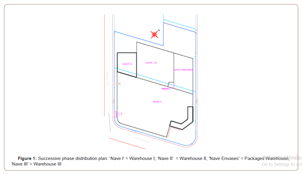
It is also important to note that in the consequent development of each phase, foresight into the future has been taken into account, and in the 10-year period, the development of the phases has been adapted to the different regulations and specification changes (Figure 1).
Case Study Explanation
Conditioning and Phases
As mentioned, the first phase structures (warehouses I and II) were built in 2007 (Figure 1) constrained by the growing activity of the company without the possibility of expanding beyond the inside of the urban plot in the village. The second phase consisted of a warehouse for cardboard packaging for producing the final product. The second phase took place in 2016, (Fig. 1) with the goal of creating a new reorganized and optimized warehouse for packaging instead of performing packing functions inside of warehouses I and II, which would limit the machinery operation areas and the whole process. The third and more recent phase (warehouse III) covered all the allowed construction possibilities and was located between the main warehouse I, the packaging warehouse, and warehouse II and was used as a fruit reception building. Three of the facades and their structures were utilized, minimizing construction costs of the new building.
A summary of the actuation phases and occupied surface areas is shown below (Table 1).
Table:Successive development of the phases and occupied surface area.

Description and justification of the plant layout evolution
The primary products are pomelos. The industry was initially planned to process 10.000. 000 kg/year. The production ratio was 7.000 kg/h, approximately 300. 000 kg per week.
The pomelo processing operation is quite similar to that of oranges.
1. Fruit Reception: Pomelos from orchards are delivered in trucks and unloaded on docks. The workers in this area are in charge of the reception, quality and documentation traceability of the pomelos, and they prepare the subsequent operations.
Degreening and/or fridge conservation: The objective of degreening is to provide commercial color for the variety of pomelos. When the rest of the maturity conditions are verified, fridge conservation takes place in the same refrigerated chambers to regulate field flux entrances and sweetness of the pomelos.
Confectioning: Product confectioning takes place in a machinery line. The following sections can be distinguished:
A. Fruit entrance: The fruit enters through automatic depalletizes and dumpers.
B. Previous triage: The fruit that is not suitable for commercialization is separated.
C. Treatment: The treatment process is comprised washing, air drying, and waxing the fruit.
D. Selection: The fruit is organized based on several qualities.
E. Electronic calibration: The pomelos are organized and classified by weight, size and appearance and prepared for the following section.
F. Packaging: The pomelos are packaged in wood or cardboard boxes, and in plastic nets or bags according to the client or market destination.
G. Palletizing: After a quality control verification, the packed pomelos are labelled, with conformity and traceability, and finally palletized for shipping.
Precooling: The finished product is taken to the refrigerated chambers and further transported in chilled trailers through special docks.
All these aspects were taken into account for the activity and environmental license phase in 2007 (first phase) (Figure 2).
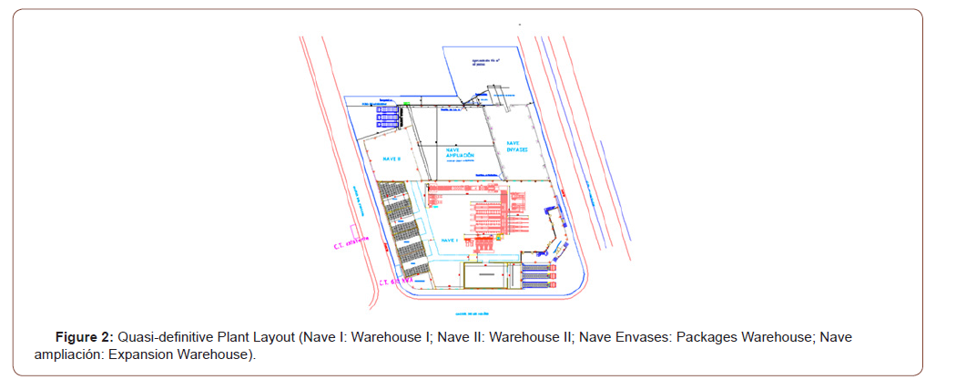
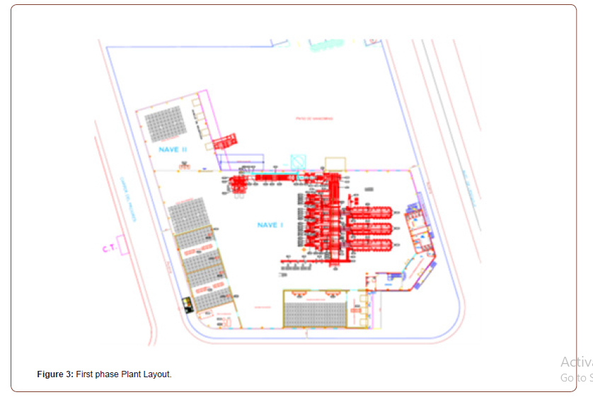
The second phase (2016) took place because of the different types of packaging (mainly cardboard packages) as a consequence of Pomelos MBC growing and commercializing its own trademarks, as well as to differentiate from other important citrus industries with many other trademarks. This aspect required substantial spaces and areas and the ability to confine all the packages in an organized way inside a new building that was exclusively for them, avoiding the risk of fire and other hazardous aspects. Finally, in 2017, it was decided that because of the increasing production and forecasting of the future a new project was initiated to build in the rest of area where there was no constructed and to reorganize and extend the machinery lines (Figure 3). The new warehouse (III) was employed for fruit reception and for the ‘dirty’ part of confectioning, which involved previous triage, treatment and selection, doubling lines, and employing warehouse I for electric calibration and packaging (‘clean’ zone) with new machinery. Warehouse III and I were finally separated but with communication entrances or passes. The new production ratio will exceed 20. 000. 000 kg/year, doubling previous production ratios, and allowing for work with more than 30 different fruit calibers to satisfy the requirements of the market. Additionally, in this last phase, new elements were designed to collect and treat industrial wastewater and fruit without commercial or industrial utilization. It is worth noting that the designed buildings are quite light and do not have intermediate columns, in other words, the buildings are very open and with substantial versatility for the distribution of the machinery. Additionally, the shape allows for an excellent natural illumination degree and natural convective ventilation, from the low parts of the external walls to the top ceiling, providing an excellent natural environment and comfort for the activities performed.
Description and justification of the different buildings developed for each phase
Every phase of the project has followed the corresponding Valencian and Spanish legal filings for the industry. As discussed in the former section, the first building project dates from 2007, with the plant layout and distribution exposed. Mainly, this phase was concerned with covering a large surface area for machinery disposition (warehouse I), an opened fruit reception building with docks (warehouse II) for logistical operations, and an office space, with toilets, dressing rooms, laboratory, and other facilities, taking advantage of a corner of warehouse I (Figure 3). The structural project goals were to design a warehouse with an open layout, a minimal number of intermediate supports, and an over elevated covering to provide more natural illumination space and convective zenithal ventilation. As background to the spatial structural typology, the authors have participated in a Spanish Patent P200200989 [2] and it was published in part with the erected examples in [3]. These typologies correspond to lightweight spatial structures designed with structural steel [4-6]. Moreover, the authors are members of the prestigiously International Association for Shell and Spatial Structures [7]. Additionally, several examples were exposed at the 20th International Congress on Project Management and Engineering [8]. In the references, a structural typology that consists of double pitched roof portal frame sections for large spans (50 m in this case) is described. These portal frames are spatially supported by a central longitudinal truss. From the bottom chord, two boars (one for each lintel) link both elements in a third or quarter of the free span. The lintel is also linked to the upper chord at the ridge cap. Thus, their deflection is minimized, as are the stresses, providing light profiles and sections. The parts of the lintels from the intersection with the boars to the ridge caps are tensioned, and the boars are compressed, decreasing the spatial structure deformations. For this case, the longitudinal truss has an 80 m span, with a unique column in the middle and another two at the extremes in the end portal frames (Figure 3 & 4).
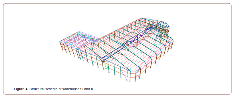
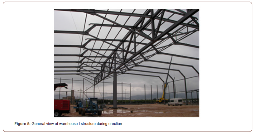
For each case, the calculation and design were performed with the finite element software package SAP2000 [9]. The typology developed for warehouse I provided refinement, improvement and innovation in its conception. The central longitudinal truss was not uniform in height. The segment near the end portal frames was 3, 5 m high, while the central segment (40 m span) was 5 m high, and the roof was uplifted. The lintels were designed to adapt to different heights to allow for the installation of polycarbonate skylights and continuous openings for ventilation. The portal frames in the lateral facades were also designed for skylight disposition. The result produced an optimum design, providing substantial volume, height, lightness, openness, and a pleasant and elegant esthetic appearance (Figure 5).
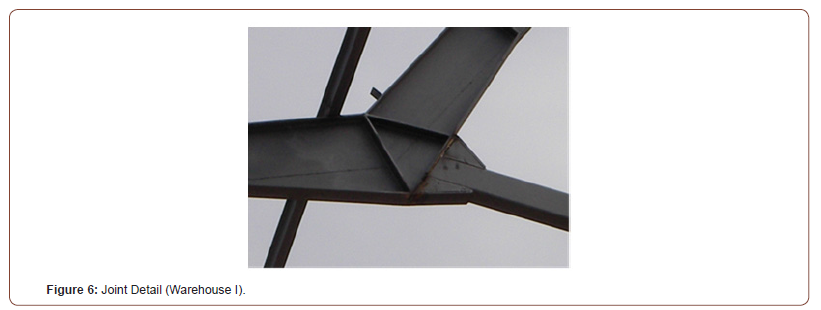
Furthermore, many special types of joints were designed, which are not detailed here because of the length requirements of the article (Figure 6).
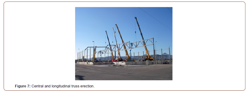
The erection began with the supports, namely, the external supports and the middle support. Its section was a circular steel hollow section, and it was filled with concrete. Next, the central truss was erected. This was transported from the workshop in parts because of its length and welding of the special joints were finished and tested with ultrasonic proofs. The truss was standing upright and lifted as a whole piece with several cranes. Due to its importance, local television channels filmed and reported the affair. The erection process was a success (Figure 7).
The erection and the project were performed following Spanish Steel and European Specifications and Building Codes [10-12]. Subsequently, transversal portal frames were placed, separated by 6,278 m, providing the spatial behavior and bracing and stabilizing the structure until it was completed. The deformations observed during the erection corresponded with the calculated deformations. Warehouse II, which was smaller than warehouse I, was designed with an opened front side for the location of the reception docks. It was constructed with triangulated trusses with a pitched roof and a cantilever structure for protecting the fruit reception over the docks.
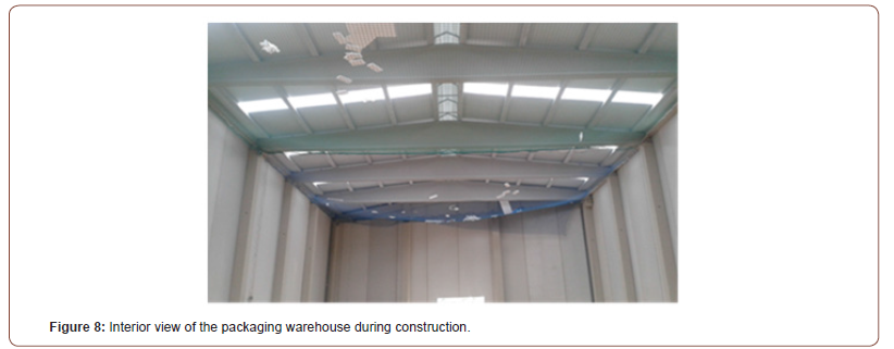
The intersection between warehouses I and II, with differences in alignment, was also constructed, and special considerations were taken into account, especially for considerations such as rainwater evacuation. Over time, the accumulation of confection packages increased, which led to the project and design of a new warehouse with the conditioning mentioned in sections 3.1 and 3.2. A high fire resistance and highly ventilated building were planned. The structure was a double pitched roof precast reinforced concrete warehouse, with a static ventilator at the ridge cap (1 m opening width) and wide windows at the low parts of the facades, which were also constructed out of precast concrete to favor ventilation. The new building was founded with eccentrically shallow foundations to not exceed the plot limits and complete the planned area. The foundations were located on asphalt pavement, which avoided excavations, and they were prepared to support the stresses of future expansions. The columns are of 0,5 m x 0,5 m reinforced concrete sections, and the frames of the precast Delta shape were made of prestressed concrete. The façade walls were also made of precast reinforced concrete. The roof was designed with special polyisocyanurate (FM) fire-resistant sandwich panels with a thickness of 60 mm (Figure 8).
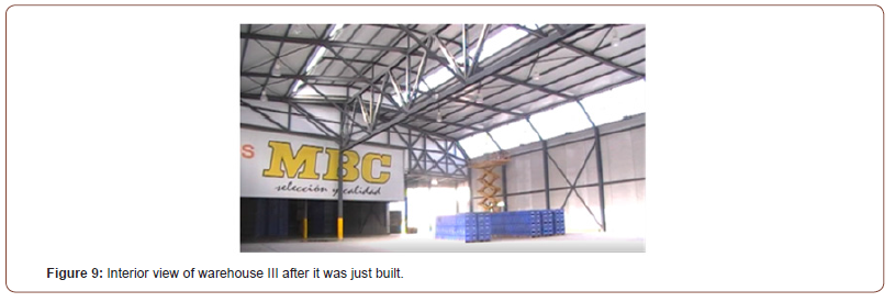
In the beginning of 2017, the documents, projects and design for warehouse III were developed. It was finished in 2018, according to the conditions referred to in the previous sections, which utilized a new arrangement and distribution for the increased processing activity. One structural requirement was that the rest of the constructible plot had a trapezoidal surface shape. The surface area was approximately 1.400 m2, with a width of 35 m and a length of 40 m, and the warehouse had to be situated between warehouse I, warehouse II and the packaging warehouse. The main advantage was that three of the facades were already built, therefore only the North façade had to be constructed. The versatility and light-weight of the steel structure to adapt to more irregular shapes encouraged the decision of choosing this material. Moreover, the structure had to cover the whole surface without intermediate columns. After the study of alternative options, the final solution was aligned with warehouse I, and the typology was also based on that warehouse I but without intermediate supports. The structure had a central triangulated longitudinal truss, with a height of 4 m with orthogonal portal frames, and a running easel. The portal frames were also ideal for the installation of the skylights and providing natural and convective ventilation. It is important to note that the existing columns and foundation of the three facades were considered in the budget with the consequent savings. The new foundations were built on the asphalt pavement and were also eccentrically loaded. As the warehouse concrete slab pavement was elevated for docking, a selected compacted soil fill was made. The degree of compaction was 95% of the modified Proctor for the first layers and 100% for the upper layers.
Regarding the spatial steel structure erection, first, the 40 m longitudinal truss was lifted after obligatory welding quality control [13], with only one crane. Next, the orthogonal portal frames were installed, providing stability, bracing, and providing the spatial configuration. As a singularity, the design and erection of the end portal frames was more delicate because of the adjustment and fitting, and for one frame, a steel shear wall truss was designed over the new docks to provide major lateral stability against lateral loads such as wind. The whole integration of the frames was very satisfactory. In the concrete slab on grade, some small stainless steel channels were installed to collect industrial wastewater, and other elements (Figure 9).
Description and justification of more relevant facilities and installations
As mentioned before, natural lighting and ventilation have been popular requests for building design. Regarding artificial lighting, despite the recent development LED technology in lamps, metallic halogen uric lamps were adopted. This is because, taking into account the natural lighting degree in one part of the building and considering that the needed hours of artificial lighting are very limited in other parts, the investment in LED lamps was not profitable with the long payback periods. The electrical transformer substation (630 kVA) was placed next to the machinery control room. Inside there were also compressors for refrigeration and the general commands for the installations to minimize voltage drops and energy losses. From this general command, the 12 secondary command boxes are fed. Based on Spanish Building Code CTE-DB-SUA8, a lightning conductor was utilized with a priming device and protection grade 4 (60 m protection radius), with a minimum withstand current of 100 KVA. The lightning conductor was installed on the roof with a 6 m height galvanized steel mast. The refrigeration facilities included two refrigerating/ degreening chambers, one for fruit transportation and one for chilled transportation docks. The chamber walls and ceilings were covered with polyisocyanurate sandwich panels with a thickness of 100 mm without thermal bridges and with tongue and groove joints. The concrete pavement chambers were isolated by installing shells from an asphaltic emulsion that was made of an anti-vapor barrier.
A ‘C’ gasoil tank was also installed according to Spanish Specifications for Petroleum installations to supply power (40 l/h) for the predrying and drying tunnels.
Conclusion
Agro-citrus industry warehouses are very common in the Spanish Valencian Community, which contains many orchards. Because of machinery disposition and storage, they require a great surface area to perform all the activities from fruit reception to the transportation and maneuvering of trucks and fork-lift trucks.
This industry is a well-known shipper of fruit to the rest of Europe and other countries around the world.
Therefore, such companies are continuously expanding and growing, and they have new requirements for buildings and facilities. In the case of this study, the solutions and phase development of an exclusive pomelo citrus industry facility have been described. The market demands, future expansions and activity needs were considered, thus providing singular open buildings for the successful implementation of the company requirements, which were designed by the authors.
Acknowledgement
None.
Conflict of Interest
No conflict of interest.
References
- Ayuntamiento de Miramar (2001) Normas urbanísticas propias de la ordenación pormenorizada. Capítulo IV, Valencia.
- Ferrer CM, Ferrán JJ, Patente P (2002) Perfeccionamientos introducidos en estructuras armónicas para arquitectura industrial.
- Ferrer CM, Ferrán JJ, Torregrosa JB, Ferrer CMG, Sánchez FJ (2007) Light structure examples for industrial architecture. Journal of the International Association for Shell and Spatial Structures 48 (154): 119-129.
- Barnes M, Dickson M (2000) Widespan Roof Structures. Thomas Telford.
- Parke GAR, Howard CM (1993) Space Structures. Thomas Telford.
- Engel H (2000) Sistemas de estructuras. Gustavo Gili.
- IASS – International Association for Shell and Spatial Structures.
- Ferrer PS, Ferrer CM, Redón M, Torregrosa JB, Ferran JJ, et al. (2016) Arte estructural en edificios agroindustriales. 20th International Congress on Project Management and Engineering, pp.618-628.
- CSI (Computers and Structures Inc.) Analysis Reference Manual (2016).
- Eurocode 3 (2009) Design of steel structures - Part 1-1: General rules and rules for buildings.
- CTE (Código Técnico de la Edificación (2006) Ministerio de Fomento.
- EAE (Instrucción de Acero Estructural) (2011) Ministerio de Fomento.
- UNE-EN ISO 17640:2011. Ensayo no destructivo de uniones soldadas. Ensayo por ultrasonidos. Técnicas, niveles de ensayo y evaluació
-
Carlos Ferrer, Pablo Ferrer, Javier Ferrán, Miguel Redón. Project and Design of a Special Agricultural Warehouse Developed in Phases in Valencia (Spain). Cur Trends Civil & Struct Eng. 5(5): 2020. CTCSE.MS.ID.000623.
-
Spatial and lightweight steel warehouses, Erection, Development in phases, Project management
-

This work is licensed under a Creative Commons Attribution-NonCommercial 4.0 International License.


