 Research Article
Practical Design and Modelling of Precast Concrete Structures
Morten A Herfelt1, Jørgen Krabbenhøft1 and Kristian Krabbenhøft1,2*
1Optum Computational Engineering, 2400 Copenhagen NV, Denmark
2Civil Engineering and Industrial Design, University of Liverpool, UK
Kristian Krabbenhøft, Civil Engineering and Industrial Design, University of Liverpool, Liverpool L69 3BX, UK.
Received Date: July 15, 2019; Published Date: July 23, 2019
Abstract
Precast concrete structures are conventionally designed using manual methods and simplified numerical tools, e.g. linear finite element analysis, hence, structures are often far too conservative thus wasting con- crete and reinforcement. Moreover, the quality of the design is to a large degree reliant on the skill and engineering intuition of the structural engineer. Finite element limit analysis provides a framework for efficient analysis using mathematical programming. Plane stress elements for modelling precast panels are reviewed and a composite model for reinforced concrete is presented. A four storey shear wall is analyzed using the commercial software Optum Concrete Solution: The model includes mesh reinforcement, column- and beam reinforcement, stringers and joints, and the limit load is calculated in a matter of seconds. The example displays that the use of finite element limit analysis has the potential to greatly optimise precast structures, hence, making our structures more sustainable as well as cheaper.
Keywords: Precast concrete; Limit analysis; Rigid plasticity; Finite element; Numerical modelling
Introduction
Precast concrete has many advantages over conventional insitu cast concrete. It is cast and cured in a controlled environment which allows for increased quality control and, therefore, makes it possible to decrease many tolerances. The precasting enables parallel production, which increases the speed and efficiency considerably. The fib Bullitin 43 [1] describes many of the common techniques for precast concrete elements. The production of precast elements at the manufacturer also means that the construction is less labour intensive. Some work is nevertheless still required at the construction site as the precast elements need assembly, which is handled by various kinds of concrete or mortar joints cast in place. These joints are often crucial to the overall behaviour of the structure; however, they also introduce additional complexity to the structure for the structural engineer. For practical design and analysis of precast concrete structures, conventional finite element analysis is rarely used. Adopting a simple linear elastic approach leads to a far too conservative design. More advanced models, however, requires expert knowledge by the user as well as material models capable of handling the complexity of the precast structure and joints. Moreover, non-linear finite element models can be prone to numerical difficulties. The engineers are therefore left with simplified methods based on limit analysis, i.e. the assumption of a rigid-plastic material, e.g. the yield line method [2,3] or stress field methods [4]. While being easy to use, these methods are difficult to master, and the solutions will depend heavily on the skill and intuition of the individual structural engineer.
Finite element limit analysis (FELA) combines the rigid-plastic material model of limit analysis with the discretisation known from finite element analysis (FEA). The result is a so-called direct method, where the limit load is calculated in a single step rather than the conventional load step scheme of FEA. The formulation of FELA is a convex optimization problem, and Anderheggen and Knöpfel [5] were some of the first to present this for linear optimisation. During the 90s optimisation techniques and algorithms were extended tremendously [6-8], and solving convex programs is an established technology at this point. During the 2000s various researchers extended the scope of FELA from the original formulation of linear programming to both second-order conic programs and semidefinite programs [9-11]. Limit analysis and FELA assume a simplified material behaviour, i.e. rigid plasticity, however, the result is an elegant formulation which allows rigorous bounds on the exact limit load. Naturally, lower bound solutions are appealing since they ensure a safe and statically admissible stress field. Moreover, complex features such as joints, interfaces, and various reinforcement layouts can be dealt with in a simple and efficient manner within FELA making it an alluring design tool [12,13]. In this paper, an overview of design of precast concrete structures using FELA and the newly developed software Optum Concrete solution is given. More precisely, the case of shear walls comprised of precast panels is considered. Such structures, while common, pose a considerable challenge in the ultimate limit state, hence, leading to suboptimal designs and wasted resources.
Finite Element Limit Analysis
As discussed in the introduction, FELA assumes a rigid-plastic material behaviour, which simplifies the problem at hand greatly. Moreover, the problem is formulated in terms of stresses rather than displacements. The general formulation of FELA is given as follows:

where the load consists of a constant part, p0 , and a scalable part, pλ ,where λ is a so-called multiplie which is sought to be maximised. The linear equations ensure equilibrium with BT being the equilibrium matrix, while the yield condition f is enforced for every stress node i. Assuming a convex yield function, (1) represents a convex optimisation problem, which can be solved remarkably efficiently and robustly using interior point methods. Many yield criteria relevant to civil engineering can be represented using conic sections, e.g. von Mises criterion for metals, the Mohr-Coulomb criterion for plane stress, and Nielsen’s criterion for plates [10,11].
Precast panels
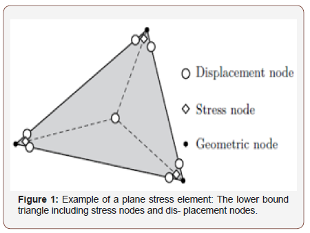
As discussed in the introduction, shear walls are crucial in precast structures, yet difficult to design and analyses using conventional methods. Computationally, a panel can be represented accurately using plane stress triangles, whereas several has been developed for FELA [14-16] (Figure 1).
The shear walls comprise several precast panels as well as joints, and the panels themselves typically contain two layers of mesh reinforcement as well as various stirrups and rebars near openings and edges. An adequate yield function for concrete with smeared reinforcement is needed and for that purpose a composite approach is taken: The total stresses are split into concrete and reinforcement stresses accordingly:

where σc represents the concrete stresses, and  represents
the equivalent reinforcement stresses, i.e.

where si A is the reinforcement area per unit length in the ith direction and t is the thickness of the panel. For the reinforcement, the following criterion is enforced:

where fyx and fyy are the yield strengths in the x and y-directions, respectively. For the concrete stresses, the conventional Mohr- Coulomb criterion including a tension cut-off is used:

where σ1 ≥ σ2 are the two principal concrete stresses, while ft and fc are the uniaxial tension and compression strengths, respectively. The Mohr-Coulomb criterion can be modelled using linear and second-order conic constraints and will therefore fit the format of second-order cone programming.
Example
In this section, a complete shear wall will be analysed using Optum Concrete Solution (OptumCS). The modelling itself is done in 3D, and a single model can contain an entire building. The analysis of the shear walls, on the other hand, is done in 2D assuming a plane stress state. Conventionally, complex geometry combined with lateral forces, e.g. wind load, is problematic to analyse, however, using FELA the capacity of the structure including the actual reinforcement layout can easily be assessed. For further information about elements and material models, the reader is refered to [17]. The structure shown in Figure 2 comprise four storeys, each with several holes, which all has a height of 2300 mm. The wider holes have a width of 2400 mm, while the smaller holes have a width of 1000 mm. The panels have a thickness of 200 mm with a characteristic concrete strength of 30 MPa. Using a partial coefficient of 1.40 and an effectiveness factor ν of 0.50, we arrive at an effective design strength of 10.7 MPa. The tensile strength of the concrete is neglected as is common for rigid-plastic analysis due to the brittle nature of concrete in tension. The panels are reinforced with two layers of Ø6 bars per 150 mm with a design strength of 417 MPa (Figure 2).
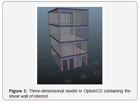
Figure 3A shows beam (purple) and column (pink) reinforcement zones. The reinforcement zones re- place the ordinary mesh reinforcement. The beam reinforcement zones comprise two Ø12 bars in the bottom of the zone as well as closed Ø8 stirrups per 150 mm. The column zones comprise four Ø10 bars, one in every corner, and closed Ø8 stirrups per 150 mm. Moreover, Ø20 stringer reinforcement in each side of the shear wall is used to carry the overturning moment from the lateral loads. A single vertical joint split the shear wall in two. The joint itself is reinforced with Ø6 U-bars per 300 mm. A friction coefficient of 0.75 and a cohesion of zero are used. The horizontal joints are indicated in Figure 3B as the white rectangles just below each level, and they are reinforced with Ø8 bars per 300 mm coupled with a coefficient of friction of 0.75 and a cohesion of 0.50. The horizontal joints have a reduced effective width of just 100 mm; hence, large compressive stresses are expected. All reinforcement has a de- sign strength of 417 MPa. Figure 3B indicates the load acting on the structure. The wall is subjected to a fixed vertical load on every storey of 22.5 kN/ m2, while horizontal load is sought to be maximised. The bottom three storeys are subjected to 45 kN each while the top storey is subjected to 22.5 kN, hence, the total horizontal load is 157.5 kN (Figure 3A,3B).
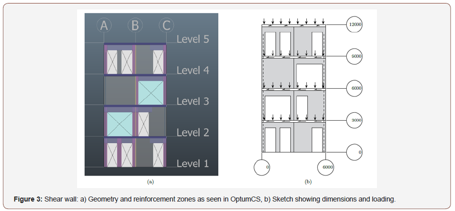
Table 1:Load multiplier and computational time for the shear wall.
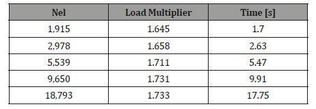
(Table 1) The results for the shear walls are summarized in Table 1. For references, all calculations are performed on an Intel i5 7600k processor with 4 cores and 3.8 GHz. It is observed that the load multiplier converges rapidly, and the coarsest mesh of 1915 elements produce a limit load approximately 5 % below the finest mesh. It is also observed that the computational time is approximately proportional to the number of elements, which means that large models can be solved efficiently.
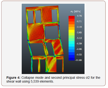
(Figure 4) The collapse mode of the shear wall is displayed in Figure 4: Several plastic hinges in the slender columns and beams develop which in combination with yielding of the leftmost stringer causes failure of the structure. Moreover, separation is observed in several interfaces showing the importance of the joints in the structural behaviour. The analysis yielded a load multiplier of approximately 1.73, hence, the presented design is more than sufficient for the analysed load case. Figure 4 also shows the second principal stress, which indicates that the loads are carried by means of strut action in the beams and columns.
Conclusion
Precast structures are difficult to analyse using conventional methods. This paper has displayed how finite element limit analysis can form an efficient and robust framework, where the use of mathematical programming ensures that the problem can solved rapidly using state-of-the-art methods. Reinforced concrete as a material can be modelled accurately in the limit state as a composite material, which fits the format of second-order cone programming. Using the newly developed commercial Optum Concrete Solution, a four storey shear wall with several openings is analysed. The wall includes various re- enforcement zones, joints and stringers making it difficult to assess the capacity using conventional methods. Using FELA and OptumCS, on the other hand, the limit load is calculated in a matter of seconds. The collapse mode and stress field clearly show the structural behaviour which, in combination with a computational time of mere seconds, makes FELA a prime tool for design and analysis of precast concrete structures. Based on trials in the industry, it is estimated that the use of finite element limit analysis can amount of reinforcement by approximately 40 % compared to conventional methods, thus making our built environment more sustainable.
Acknowledgement
The authors would like to thank Innovation Fund Denmark for financial support for the research presented in this paper.
Conflict of Interest
No conflict of interest.
References
- Fib bulletin 43 (2008) Structural connections for precast concrete buildings. fédération internationale du béton (fib).
- Johansen KW (1962) Yield-line theory. Cement and Concrete Association.
- Nielsen MP, Hoang LC (2010) Limit Analysis and Concrete Plasticity. Taylor & Francis.
- Muttoni A, Schwartz J, Thürlimann B (1997) Design of Concrete Structures with Stress Fields. Springer.
- Anderheggen E, Knöpfel H (1972) Finite element limit analysis using linear programming. International Journal of Solids and Structures 8: 1413–1431.
- Nesterov Y, Nemirovsky A (1988) A general approach to polynomialtime algorithms design for con- vex programming. Report, Central Economical and Mathematical Institute, USSR Academy of Sciences, Moscow.
- Nesterov YE, Todd MJ (1997) Self-scaled barriers and interior-point methods for convex programming. Mathematics of Operations research 22(1): 01–42.
- Andersen ED, Roos C, Terlaky T (2003) On implementing a primal-dual interior-point method for conic quadratic optimization. Mathematical Programming 95(2): 249–277.
- Makrodimopoulos A, Martin C (2006) Lower bound limit analysis of cohesive-frictional materials using second-order cone programming. International Journal for Numerical Methods in Engineering 66(4): 604–634.
- Krabbenhøft K, Lyamin A, Sloan S (2007) Formulation and solution of some plasticity problems as conic programs. International Journal of Solids and Structures 44(5): 1533–1549.
- Bisbos C, Pardalos P (2007) Second-order cone and semidefinite representations of material failure criteria. Journal of Optimization Theory and Applications 134(2): 275–301.
- Herfelt MA, Poulsen PN, Hoang LC, Jensen JF (2016) Numerical limit analysis of keyed shear joints in concrete structures. Structural Concrete 17(3): 481–490.
- Herfelt MA, Poulsen PN, Hoang LC, Jensen JF (2017) Lower bound equilibrium element and sub- model for shear joints in precast concrete structures. Engineering Structures 135: 1-9.
- Sloan SW (1988) Lower Bound Limit Analysis Using Finite Elements and Linear Programming. International Journal for Numerical and Analytical Methods in Geomechanics 12: 61–77.
- Sloan SW (1989) Upper Bound Limit Analysis Using Finite Elements and Linear Programming. International Journal for Numerical and Analytical Methods in Geomechanics 13: 263– 282.
- Poulsen PN, Damkilde L (2000) Limit State Analysis of Reinforced Concrete Plates Subjected to In- plane Forces. International Journal of Solids and Structures 37: 6011–6029.
- Herfelt MA (2017) Numerical Limit Analysis of Precast Concrete Structures: A framework for efficient design and analysis. Technical University of Denmark, Department of Civil Engineering. Building 118, Brovej, 2800 Kgs. Lyngby, Denmark.
-
Kristian Krabbenhøft, Morten A Herfelt, Jørgen Krabbenhøft. Practical Design and Modelling of Precast Concrete Structures. Cur Page 4 of 4 Trends Civil & Struct Eng. 3(2): 2019. CTCSE.MS.ID.000560.
-
Precast concrete, Limit analysis, Rigid plasticity, Finite element, Numerical modelling, Optum concrete, Finite element, Construction, Reinforcement
-

This work is licensed under a Creative Commons Attribution-NonCommercial 4.0 International License.


