 Review Article
Literature Review: Concrete Filled Steel Tubes Under Transverse Impact Loading
Khalid Abdel Naser Abdel Rahim, Department of Civil Engineering, Faculty of Science and Technology, University of Coimbra, Rua Luis Reis dos Santos 290, 3030-790 Coimbra, Portugal.
Received Date: April 19, 2021; Published Date: June 10, 2021
Abstract
This literature review paper presents the latest technologies, designs and technics which has been used to improve the transverse impact resistivity of Concrete Filled Steel Tubes (CFST). Moreover, this literature review paper has included past researchers in the field since 1976 up to 2020. Different types of concrete filled steel tube designs and materials subjected to lateral/transverse impact load were discussed, for example, (1) Concrete Filled single skin Steel Tubular - CFST, (2) Concrete Filled Double skin Steel Tubular - CFDST, (3) Concrete Filled Stainless Steel Tubular - CFSST, (4) High Strength Concrete-Filled Steel Tubular - HSCFST, (5) Concrete Filled Steel Tubular - CFST structural elements strengthened with Fiber Reinforced Polymer - FRP, (6) Reinforced Steel Concrete Filled Steel Tubular - RSCFST, (7) Partially Concrete-Filled Steel Tubular - PCFST structural elements. Besides, the methodologies used by past researchers were argued in terms of geometrical properties, type of analysis, material properties, cross sectional dimensions and boundary conditions of CFST’s. In addition, the numerical mesh, elements, loading conditions used by previous studies were illustrated. Furthermore, the results of previous researchers were examined in terms of failure modes, Impact Force versus Impact Time and Mid-span Deflection versus Impact Time and residual displacements. The core of the problem is the high deflection magnitudes in CFST structural members after being exposed to transverse impact loads. As such, this literature review paper proposes an innovative hybrid design using composite materials to improve the resistivity of concrete filled steel tubes after being exposed to transverse impact load.
Keywords:Literature review; CFST; Carbon steel; Normal strength concrete; Transverse impact load
Numenclature
Table 24:

Introduction
Thomas et al. [1] large deformations of thin-walled circular tubes under transverse loading – I: An experimental survey of the bending of simply supported tubes under a central load. Furthermore, Watson et al. [2] performed experiments on the bending of simply supported tubes to investigate large deformations of thin-walled circular tubes under transverse loading. Also, Watson [3] studied large deformations of thin-walled circular tubes under transverse loading by conducting experimental study of the crushing of circular tubes by centrally applied opposed wedge-shaped indenters. Goode & Fatheldin [4] has studied sandwich cylinders (steel-concretesteel) subjected to external pressure. Moreover, De Oliveira et al. [5] examined the plastic behavior of tubular members under lateral concentrated loading. Besides, Soreide & Amdahl [6] studied the deformations characteristics of tubular members with reference to impact loads from collisions and dropped objects. In addition, Abramowicz & Jones [7] studied the dynamic axial crushing of square tubes. Also, Xiaoqing & Stronge [8] investigated a spherical missile impact and perforation of filled steel tubes. Bischoff & Perry [9] studied the compressive behavior of concrete at high strain rates. Likewise, Tomii [10] presented ductile and strong columns composed of steel tube, in-filled concrete and longitudinal steel bars. Furthermore, Bergmann [11] did a load introduction in composite columns filled with high strength concrete. Also, Lu & Kennedy [12] investigated the flexural behavior of concretefilled hollow structural sections. Additionally, Bergmann et al. [13] did a CIDECT design guide for concrete filled hollow section columns under static and seismic loading. Moreover, Mays & Smith [14] discussed and presented the blast effects on buildings. Furthermore, Wei et al. [15] did an experiment on new sandwich tube to examine its performance under axial loading. Also, Jones & Birch [16] investigated the influence of internal pressure on the impact behavior of steel pipelines. Besides, ASCCS [17] did a research on concrete filled steel tubes as part of studying the steel-concrete composite structures. In addition, The Association for International Cooperation and Research in Steel-Composite Structures [18] conducted a comparison between international codes and practices on concrete filled steel tubes. Also, Jones [19] has discussed and gave examples on structural impact behavior. Moreover, Shen & Chen [20] did an investigation on the impact performance of steel pipelines.
Burgan et al. [21] did a structural design of stainless-steel members comparison between Eurocode 3, Part 1.4 and test results. Furthermore, Hajjar [22] investigated concrete-filled steel tube columns under earthquake loads. Also, Rasmussen [23] presented the recent research on stainless steel tubular structures. Moreover, Elchalakani et al. [24] examined concrete-filled circular steel tubes subjected to pure bending. Besides, Morino et al. [25] discussed the concrete-filled steel tube column system and its advantages. Additionally, Rasmussen [26] did a research report at Centre for Advanced Structural Engineering, The University of Sydney on full-range stress–strain curves for stainless steel alloys. Also, Shanmuam & Lakshmi [27] presented state of the art report on steel–concrete composite columns. Moreover, Elchalakani et al. [28] tested concrete filled double-skin (CHS outer and SHS inner) composite short columns under axial compression. Furthermore, Elremaily and Azizinamini [29] studied the behavior and strength of circular concrete-filled tube columns. As such, Morino and Tsuda [30] conferred the design and construction of concrete-filled steel tube column system in Japan. Besides, Zeinoddini et al. [31] did an experimental study on axially pre-loaded steel tubes subjected to lateral impacts. Also, Elchalakani [32] studied the cyclic bending behavior of hollow and concrete-filled cold formed circular steel members. Furthermore, Hu et al. [33] did a nonlinear analysis of axially loaded concrete filled tube columns with confinement effect. Moreover, Liu [34] studied the ultimate capacity of high-strength rectangular concrete-filled steel hollow section stub columns. In addition, Mursi & Uy [35] argued about the strength of concrete filled steel box columns incorporating interaction buckling. Also, Nethercot [36] presented and discussed the different types of composite construction. Furthermore, European Committee for Standardization [37] has established Eurocode 4 - Design of composite steel and concrete structures: Part 1.1 – General rules and rules for buildings. EN 1994-1-1:2004: E. Moreover, Fam et al. [38] researched concrete-filled steel tubes subjected to axial compression and lateral cyclic loads. Also, Gho & Liu [39] investigated the flexural behavior of high-strength rectangular concrete-filled steel hollow sections. In addition, Han [40] studied the flexural behavior of concrete-filled steel tubes. Furthermore, Zhao [41] studied CFRP strengthened butt-welded very high strength (VHS) circular steel tubes. Sakino et al. Moreover [42] examined the behavior of centrally loaded concrete-filled steeltube short columns. Also, Varma et al. [43] studied the seismic behavior and design of high-strength square concrete-filled steel tube beam columns. Adding to the above, The European Committee for Standardization [44] has established Eurocode 1 - actions on structures part 1–7 general actions and accidental actions. Additionally, The European Committee for Standardization [45] has established draft prEN 1991-1-7, Eurocode 1-Actions on Structures. Part 1–7: General Actions-Accidental actions. Moreover, Gardner [46] discussed the use of stainless-steel material in structures. Furthermore, Han & Yang [47] examined the cyclic performance of concrete-filled steel CHS columns under flexural loading. Besides, Xiao et al. [48] presented and discussed confined concrete-filled tubular columns. Also, Ellobody & Young [49] designed and analyzed the behavior of concrete-filled cold-formed stainless-steel tube columns. In addition, Ellobody & Young [50] experimentally investigated concrete-filled cold-formed high strength stainless steel tube columns. Also, Habel et al. [51] developed the mechanical properties of an ultra-high-performance fiber reinforced concrete (UHPFRC). Moreover, Han et al. [52] examined concrete-filled double skin steel tubular (CFDST) beam-columns subjected to cyclic bending. Furthermore, Japan Society of Civil Engineers [53] gave recommendations for design and construction of Ultra High Strength Fiber Reinforced Concrete (UHSFRC) structures. Besides, Rasmussen & Ranzi [54] tested the strength of concrete-filled stainless-steel tubes under impact loading. Additionally, Han et al. [55] studied the performance of concrete-filled thin-walled steel tubes under pure torsion. As well, Kang et al. [56] examined the flexural behavior of concrete-filled steel tube members and its application. Besides, Rasmussen & Ranzi [57] explored the strength of concrete-filled stainless-steel tubes under impact loading. Moreover, Shan et al. [58] inspected the behavior of concrete filled tubes and confined concrete filled tubes under high-speed impact. Also, Tao et al. [59] studied the compressive and flexural behavior of CFRP repaired concrete-filled steel tubes after exposure to fire. Furthermore, Uy & Remennikov [60] studied the behavior of concrete filled steel columns subjected to transverse impact loads. Also, Baddoo [61] has reviewed the research, application, challenges and opportunities on stainless steel in the construction industry. As well, Bambach et al. [62] investigated hollow, and concrete filled steel hollow sections under transverse impact loads. Moreover, Gedge [63] conferred the structural uses of stainless steel-buildings and civil engineering. Furthermore, Gourley et al. [64] did a synopsis of studies of the monotonic and cyclic behavior of concrete-filled steel tube members, connections, and frames. Additionally, Lam & Gardner [65] has presented a structural design of stainless-steel concrete filled columns. Besides, Tao et al. [66] presented design proposal of concrete-filled steel tubular members according to the Australian Standard AS 5100 model and calibration. Moreover, Uy [67] studied the stability and ductility of highperformance steel sections with concrete infill. Furthermore, Zeinoddini et al. [68] did numerical simulation on axially preloaded steel tubes subjected to lateral impacts. In addition, Zhou & Hao [69] proposed modelling of compressive behavior of concretelike materials at high strain rate. As well, Chen et al. [70] designed a thin-walled centrifugal concrete-filled steel tubes and tested it under torsion. Furthermore, Han et al. [71] explored the performance of concrete filled steel tube reinforced concrete columns subjected to cyclic bending. Moreover, Huo et al. [72] tested the impact behavior of micro-concrete filled steel tubes at elevated temperatures up to 400°C. Also, Remennikov and Uy [73] investigated the response of rigid polyurethane foam-filled steel hollow columns under low velocity impact. Besides, Xiao et al. [74] did an experimental study on concrete filled steel tubes under high strain rate loading. Nevertheless, Yang et al. [75] investigated the experimental performance of recycled aggregate concrete filled circular steel tubular columns subjected to cyclic flexural loadings. Also, Yousuf et al. [76] experimentally examined the behavior of concrete-filled stainless-steel tubular columns under impact loading. Moreover, Chen et al. [77] has experimentally studied the mechanical behavior of recycled aggregate course concrete-filled square steel tube column. Additionally, Chitawadagi [78] investigated the axial strength of circular concrete-filled steel tube columns. Nonetheless, European Committee for Standardisation [79] has established EN1991-1-7, Eurocode 1—Actions on Structures—Part 1-7: General Actions - Accidental Actions. Furthermore, Jiang et al. [80] experimentally studied the fire exposed rectangular concrete-filled steel tubular (CFST) columns subjected to bi-axial force and bending. In addition, Lu et al. [81] experimented the fire performance of self-consolidating concrete filled double skin steel tubular columns. Moreover, Roeder et al. [82] studied the strength and stiffness of circular concrete filled tubes. Besides, Zhao et al. [83] presented and discussed various types of concrete-filled tubular members and connections. As well, Starossek et al. [84] did a numerical analysis of the force transfer in concrete-filled steel tube columns. Nonetheless, Thilakarathna et al. [85] did numerical simulation of axially loaded concrete columns under transverse impact and vulnerability assessment.
Bambach [86] designed hollow and concrete filled steel and stainless-steel tubular columns for transverse impact loads. Moreover, Chakradhara et al. [87] analyzed the behavior of recycled aggregate concrete under drop weight impact load. Besides, Cui & Xu [88] analysis the uniaxial dynamic performance of concretefilled square steel tube composite column. In addition, Deng et al. [89] studied the flexural strength analysis of non-posttensioned and post-tensioned concrete-filled circular steel tubes. Furthermore, Han et al. [90] tested stub stainless steel-concretecarbon steel double skin tubular (DST) columns. Besides, He et al. [91] studied the mechanical behavior of recycled concrete filled steel tube columns strengthened by CFRP. Also, Kim et al. [92] did a comparative flexural behavior of hybrid Ultra High-Performance Fiber Reinforced Concrete (UHPFRC) with different macro fibers. In addition, Qu et al. [93] analyzed circular concrete-filled steel tube specimen under lateral impact. Nevertheless, Remennikov et al. [94] studied the response of foam- and concrete-filled square steel tubes under low-velocity impact loading. Furthermore, Sundarraja & Prabhu [95] investigated on strengthening of CFST members under compression using CFRP composites. Besides, Tao et al. [96] did a nonlinear analysis of concrete-filled square stainless-steel stub columns under axial compression. Moreover, Uy et al. [97] examined the behavior of short and slender concretefilled stainless-steel tubular columns. In addition, Deng et al. [98] investigated the flexural behavior of concrete-filled circular steel tubes under high-strain rate impact loading. Also, Hassan et al. [99] did experimental test methods to determine the uniaxial tensile and compressive behavior of Ultra High-Performance Fiber Reinforced Concrete (UHPFRC). Besides, Xiao & Shen [100] examined the impact behaviors of CFT and CFRP confined CFT stub columns. Moreover, Yousuf et al. [101] explored the behavior and resistance of hollow and concrete-filled mild steel columns due to transverse impact loading. Additionally, Abdalla et al. [102] investigated the behavior of CFSTs and CCFSTs under quasistatic axial compression. Nevertheless, The Association Francaise de Genie Civil. [103] stated recommendations on using Ultra High-Performance Fiber- Reinforced Concretes (UHPFRC). Moreover, Deng & Tuan [104] design a concrete-filled circular steel tubes and analyzed its response under lateral impact. Furthermore, Hassanein et al. [105] examined circular concrete-filled double skin tubular short columns with external stainless-steel tubes under axial compression. Besides, Yousuf et al. [106] examined the transverse impact resistance of hollow and concrete filled stainless steel columns. Also, Alam et al. [107] did dynamic simulation of CFRP strengthened steel column under impact loading. In addition, An & Han [108] examined the behavior of concrete encased CFST columns under combined compression and bending. Nonetheless, An et al. [109] inspected the flexural performance of concrete-encased concrete filled steel tubes. Besides, Han et al. [110] applied developments and advanced applications on concrete-filled steel tubular (CFST) structural members. Furthermore, Hassanein & Kharoob [111] carried out an analysis on circular concrete-filled double skin tubular slender columns with external stainless-steel tubes. In addition, Huo et al. [112] did experimental study on impact behavior of concrete filled steel tubes at elevated temperatures up to 800 °C. Besides, Jiao & Ji et al. [113] investigated the seismic behavior and strength capacity of steel tube-reinforced concrete composite columns. Additionally, Mao et al. [114] did a numerical simulation of Ultra High-Performance Fiber Reinforced Concrete (UHPFRC) panel subjected to blast loading. Also, Wang et al. [115] investigated the experimental behavior of cement filled pipe in-pipe composite structures under transverse impact. Nevertheless, Wille et al. [116] studied the properties of strain hardening Ultra High-Performance Fiber Reinforced Concrete (UHP-FRC) under direct tensile loading. Moreover, Yoo et al. [117] studied the material and bond properties of Ultra High-Performance Fiber Reinforced Concrete (UHPFRC) with micro steel fibers. Furthermore, Yousuf et al. [118] studied the impact behavior of pre-compressed hollow and concrete filled mild and stainless-steel columns. Besides, Zhang [119] studied the impact resistant behavior of recycled aggregate concretefilled steel tubular member. Also, Alam et al. [120] studied CFRP strengthened CFST columns under vehicular impact. Nevertheless, Aslani et al. [121] predicted the axial load capacity of high-strength concrete filled steel tubular columns. Additionally, Ganesh Prabhu et al. [122] investigated the compressive behavior of circular CFST columns externally reinforced using CFRP composites. Moreover, Li [123] studied the behavior of CFDST stub columns under preload, sustained load and chloride corrosion. Besides, Park et al. [124] presented concrete-filled steel tube columns encased with thin precast concrete. Furthermore, Tran et al. [125] investigated the high-rate response of Ultra-High-Performance Fiber Reinforced Concretes (UHPFRC) under direct tension. Nonetheless, Wang et al. [126] experimentally studied the behavior of concrete filled double steel tubular (CFDST) members under low velocity drop weight impact. Moreover, Wang et al. [127] examined the impact of cement composite filled steel tubes, additionally, the analysis included experimental, numerical and theoretical simulations. Furthermore, Han et al. [128] investigated the behavior of concrete encased CFST members under axial tension. In addition, Li et al. [129] investigated the response of circular concrete-encased concrete-filled steel tube (CFST) stub columns subjected to axial compression. Likewise, Qian et al. [130] studied the analytical behavior of concrete encased CFST columns under cyclic lateral loading. Besides, Yoo & Banthia [131] presented a review on mechanical properties of Ultra-High- Performance Fiber-Reinforced Concrete (UHPFRC). Also, Zhang et al. [132] experimentally studied CFDST columns infilled with UHPC under close range blast loading. Additionally, Ban & Shi [133] reviewed the literature on high-strength steel structures. Furthermore, Le Hoang & Fehling [134] presented the influence of steel fiber content and aspect ratio on the uniaxial tensile and compressive behavior of ultra-high-performance concrete. Nonetheless, Zhang et al. [135] did experimental and numerical study of blast resistance of square CFDST columns with steel-fiber reinforced concrete.
Bambach [136] validated a general design procedure for the transverse impact capacity of steel columns. Besides, Guo et al. [137] did a constitutive model of ultra-high-performance fiber-reinforced concrete for low-velocity impact simulations. Furthermore, Han et al. [138] did a design guide for concrete-filled double skin steel tubular structures. In addition, Othman & Marzouk [139] studied the applicability of damage plasticity constitutive model for Ultra- High-Performance Fiber-Reinforced Concrete (UHPFRC) under impact loads. Besides, Wang et al. [140] did analysis behavior of CFDST stub columns with external stainless-steel tubes under axial compression. Also, Zhang et al. [141] examined the plastic behavior of circular steel tubes subjected to low velocity transverse impact. Nevertheless, Han et al. [142] presented a summary of recent research on the performance of concrete filled stainless steel tubular (CFSST) columns and joints. Moreover, Le Hoang [143] did experimental study on structural performance of UHPC and UHPFRC columns confined with steel tube. Furthermore, Li [144] examined the behavior of grout-filled double-skin steel tubular T-joint subjected to low-velocity impact. In addition, Saini & Shafei [145] investigated concrete-filled steel tube beams strengthened with CFRP against impact loads. On the other hand, Wang et al. [146] investigated the compressive behavior of hybrid double-skin tubular columns with Ultra-High-Performance Fiber-Reinforced Concrete (UHPFRC).
Overview of Past Research
The first section of this chapter introduces the life cycle of CFST structural members and some analytical studies. Afterwards, the latest studies on Concrete Filled Steel Tubular (CFST) structural elements subjected to axial compression loads has been presented in the second section. Then the third section illustrates Concrete Filled single skin Steel Tubular (CFDST) structural elements subjected to lateral/transverse impact load. Besides, the four section presents the investigation which has been conducted on Concrete Filled Double Skin Steel Tubular (CFDST) structural elements subjected to lateral/transverse impact load. Also, the Concrete Filled Stainless Steel Tubular (CFSST) structural elements subjected to lateral/transverse impact load is also discussed in the fifth section of this report. In addition, High Strength Concrete- Filled Steel Tubular (HSCFST) structural elements subjected to lateral/transverse impact load will be reported in the sixth section. As well, the Concrete Filled Steel Tubular (CFST) structural elements strengthened with Fiber Reinforced Polymer (FRP) subjected to lateral/transverse impact load has been presented in the seventh section. Moreover, the eighth section will discuss the Reinforced Steel Concrete Filled Steel Tubular (RSCFST) structural elements subjected to lateral/transverse impact load. While the ninth, tenth and eleventh sections will briefly and shortly discuss the latest review study on Partially Concrete-Filled Steel Tubular (PCFST) structural elements subjected to lateral/transverse impact load, Pre-casted segmental CFST under impact loads and Concrete Filled Steel Tubular (CFST) structural elements subjected to blast loads respectively.
Lifecycle of CFST structural members
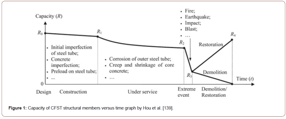
Hou et al. [147] has presented the effect of concrete-filled steel tubular (CFST) member during its life cycle. To accomplish the life cycle evaluation of CFST structural members, Hou et al. [147] conducted a numerical modelling simulation. Moreover, the numerical analysis considered the mechanical response of CFST during its life frame. Consequently, Figure 1 illustrates the capacity of CFST with relation to time during its full life cycle frame. Various factors were mentioned, with implementation on lateral impact load. Furthermore, the load-displacement, modes of failure and the residual compressive strength (Rcs) were examined. Additionally, the study has observed that the residual lateral deflection rate which is created by the impact load is the major key role effecting the residual strength (Rs) of CFST members during their life cycle (Figure 1).
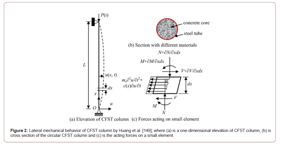
Huang et al. [148] has proposed an analytical calculative method to assist the concrete creep effect on the dynamic stability response of Circular CFST columns. Moreover, Figure 2 shows the Lateral mechanical behavior of CFST column (Figure 2).
Concrete Filled Steel Tubular (CFST) structural elements subjected to axial compression loads
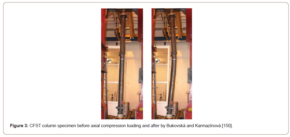
Bukovská & Karmazínová [149] has studied the buckling behavior of CFST columns under compression load as shown in Figure 3. Moreover, the concrete fillings of the CFST columns were compared between high strength and normal strength concrete. The research concluded that the tensile and shear strength increases under compression when using high strength concrete fill in CFST columns (Figure 3).
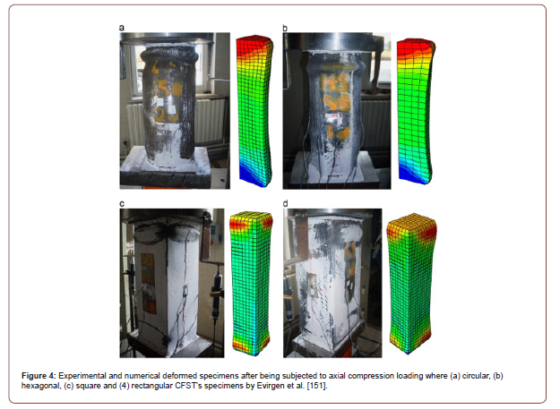
Evirgen et al. [150] performed experimental and numerical axial compression analysis on 16 hollow cold formed steel tubes and 48 CFST specimens. Moreover, three variables were assisted including concrete compressive strength, ratio of width/thickness and type of cross section. Furthermore, four types of geometrical cross sections were tested, these are circular, square, rectangular and hexagonal (Figure 4). In this study, the buckling behavior, ductility and axial stresses were investigated. It was observed that the circular geometrical CFST section is the most suitable section in terms of ductility and resistivity against axial stress. Besides, Figure 5 illustrates the experimental and numerical deformed models after being subjected to axial compression loading for all the tested geometrical CFST’s cross sectional specimens (Figures 4,5).

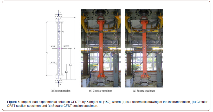
Xiong et al. [151] has studied the usage of high tensile strength steel (HTS) and ultra-high strength concrete (UHSC) in CFST columns to increase the structural performance of such elements. Moreover, Xiong et al. [151] conducted experimental and numerical simulations by applying concentric and eccentric compression loads to assist the global buckling resistivity. Besides, Figure 6 illustrates the impact load experimental setup on CFST’s structural members. Finally, Xiong et al. [151] has found that using UHSC in CFST column members has eliminated sudden structural failure and brittle (Figure 6).
Zhou et al. [152] conducted an experimental study on fifteen Concrete-Filled High-Strength steel Tubular (CFHST) stub columns with diameter-to-thickness ratios (D/t) between 50 to 130mm to investigate their behavior under axial compression load. Furthermore, Zhou et al. [152] has proposed a model to predict the ultimate capacity of CFHST stub columns subjected to axial load. Also, it was found that the strength and ductility of CFHST under axial compression increases as the Diameter-to-thickness D/t ratio increases and depending on the quality and yield strength of the steel tube. Azad & Uy [153] has investigated the local buckling and yield of hollow and concrete filled circular steel tubes under axial compression load. Moreover, Azad & Uy [153] has mentioned that the general idea of filling the hollow steel tubes with concrete is to increase the local buckling resistance by restricting its inward distortion during compression axial loading. Mohammadnejad et al. [154] conducted experimental and numerical compressive response studies on fifteen concrete-fill steel tubular circular sub column specimens subjected to external pressure. Moreover, the specimens were simultaneously subjected to axial loading and external pressure. In this research, the analysis considered two parametric variables (1) different concrete compressive strength and (2) various diameter-to-thickness (D/t) ratios. According to the results achieved by Mohammadnejad et al. [154], the external pressure rises the ductility and the load bearing capacity of the samples. Additionally, the higher the concrete compressive strength and the higher the diameter-to-thickness (D/t) ratio, the higher the ultimate strength of CFST sub columns under external pressure.
Concrete Filled single skin Steel Tubular (CFST) structural elements subjected to lateral/transverse impact load
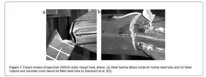
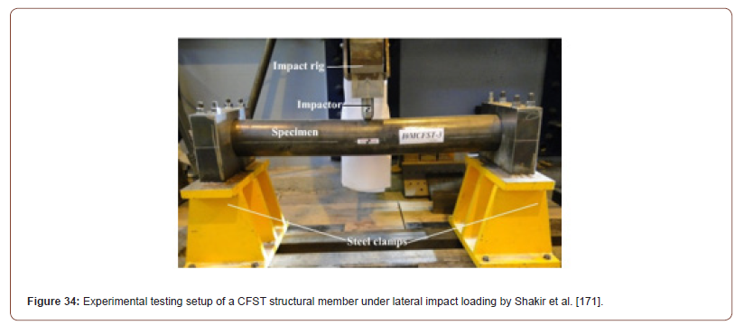
Bambach et al. [62] investigated the transverse impact behavior of concrete filled steel hollow tubes. Moreover, Bambach et al. [62] has described the simulated transverse impact load as a result of an accident or intentional act, such as blast or seismic events. Accordingly, six specimens (three hollow steel tubes and three concrete filled steel tubes) with 3 various section sizes were analyzed by applying big lateral impact weight at the mid-span of the CFST beams. Furthermore, the large impact energy was performed on the samples until achieving tensile tearing failure. Besides, Figures 7 & 8 shows the failure modes of the tested specimens after impact, while Figure 9 demonstrates the testing method and collapse mechanism of the CFST specimens. Finally, Bambach et al. [62] developed a general design method that can be used to calculate the absorbed energy to validate the subjected energy with small values (Figures 7-9).


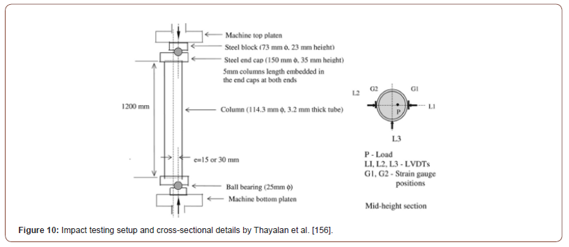
Thayalan et al. [155] did an experimental study on the static and variable repeated loading of 12 concrete-filled steel tubes and 7 hollow section tubes. In addition, the CFST columns had different length, various concrete strengths and load oddness. Furthermore, the columns response was carried on concrete filled and unfilled hollow steel tubes. Figure 10 shows the impact testing setup and details of the CFST section. Moreover, Thayalan et al. [155] has found that the ultimate strength of CFST column has decreased by 16% after being subjected to several load cycles. Finally, but never the least, the deflection at incremental collapse is contingent to the number of repeated loads and to the incremental collapse limit (Figure 10).
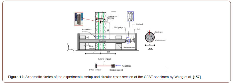
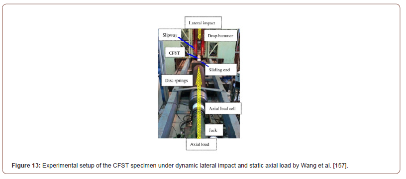
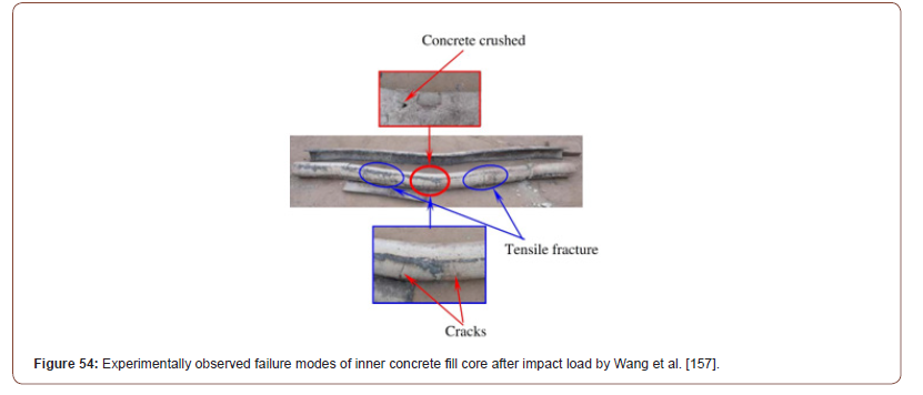
Wang et al. [156] has performed experimental and numerical analysis on the response of CFST members subjected to lateral impact load. An example of a sudden unintentional impact load was shown in Figure 11. Furthermore, the analysis has considered a static axial load in the testing procedure which represents the live and dead loads created by the slab. But the lateral impact load was dynamic and was represented by applying an impact energy from a drop hammer which weights 229.8Kg with a rigid square flat indenter (30mm×80mm). Also Figure 12 presents a schematic sketch of the experimental setup and circular cross section of the CFST specimen. While Figure 13 demonstrates the experimental setup of the CFST specimen under dynamic lateral impact and static axial load. Moreover, the height of the drop hammer was changed dramatically with an interval of 100mm. In addition, the velocity of the impact load ranged from 3.9m/s to 11.7m/s. Furthermore, the deflection was recorded, and the modes of failure were monitored. For instance, the local buckling was determined in the steel tube after impact. While for concrete, the failure modes which were observed in the inner concrete core were cracks, concrete crush and tensile fracture. Wang et al. [156] has come up to a conclusion that there is a direct effect relation between the axial load and the lateral deflections of CFST structural members subjected to lateral impact loading (Figures 11-13).

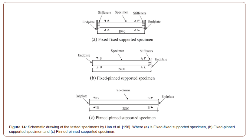
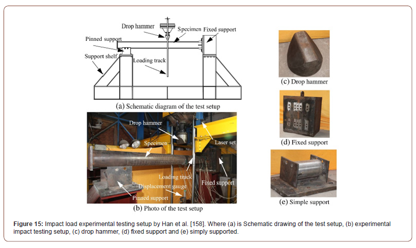
Han et al. [157] conducted an experimental analysis on 12 high strength CFST circular shaped samples. The samples were tested under transverse impact load generated by a drop hammer rig and applied on the mid-span of the tubes. Moreover, the specimens tested under 3 different types of boundary conditions. These are four samples were fixed-fixed, four fixed-pinned samples and four pinned-pinned samples (Figure 14). Furthermore, the fixed-fixed specimens had a standard length of 1940mm. While the fixedpinned specimens had a length of 2400mm, and the pinned-pinned samples had a length of 2800mm. On the other hand, specimen’s height, impact velocity, impact mass and impact energy varied rapidly. Additionally, the fixed end was represented by an end plate with stiffeners, however, the pinned end had an end plate. Figure 15 illustrates the impact load experimental testing setup. Besides, Han et al. [110] has presented the modes of failure of the analyzed specimens for both the outer steel tube and the inner concrete core. Accordingly, Han et al. [110] has observed that all the tested specimens had flexural deformation. While the inner concrete had two types of failure modes (1) tensile cracks and (2) concrete crushing. At the end, Han et al. [110] has concluded that there is a direct relation between the flexural capacity and ration of steel, yield stress of steel and diameter of section (Figures 14,15).
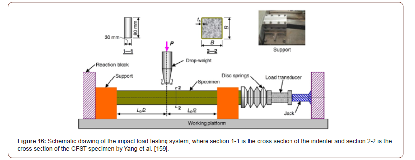
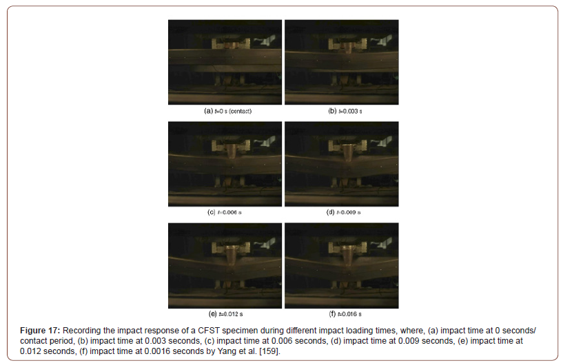
Yang et al. [158] did experimental and numerical studies on the impact load behavior of steel tube structural members filled with recycled aggregate. To achieve this, Yang et al. [158] experimented eleven RACFST samples (eight CFST filled with recycled aggregate concrete and three CFST filled with normal concrete). Moreover, the specimens were subjected to drop-weight impact test. In addition, Figure 16 shows a schematic drawing of the impact load testing system, where section 1-1 is the cross section of the indenter and section 2-2 is the cross section of the CFST specimen. Furthermore, parametric study was conducted on three variables. These are (1) ratio of axial load, (2) drop-weight height and (3) ratio of recycled aggregate in the concrete mix which was filled in the hollow steel tubes. Besides, Figure 17 illustrates the recorded impact response of a CFST specimen during different impact loading times. The simulated results obtained by Yang et al. [158] showed that the lateral impact resistance of RACFST structural members is more or less the same as that of CFST filled with normal concrete. However, the experimental peak of impact load and the predicted plateau of impact load are less than those in the CFST (Figures 16,17).
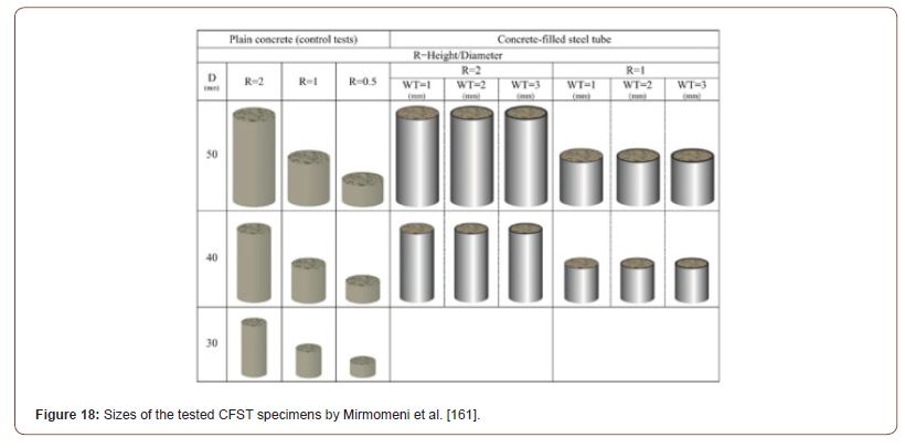
Aghdamy et al. [159] conducted a numerical analysis on circular and square sectional shaped CFST columns axially loaded and subjected to lateral impact loading. Moreover, the numerical results were compared with the experimental literature results for validation purposes and followed by a parametric sensitivity analysis. It was found that the impact behavior of CFST columns has a directly proportional relation to three main parametric factors (1) thickness of steel tube to diameter ratio, (2) impact load velocity and (3) slenderness ratio. An increase in these three parametric factors increases the impact resistivity of CFST columns. Mirmomeni et al. [160] did an experimental study on the correlation between the size and impact behavior of CFST specimens. Moreover, the material properties of the tested CFST specimens had normal concrete fill and mild steel tubes. Besides, two parametric variables were used in the analysis. Furthermore, Figure 18 presents the dimensions of the tested CFST specimens under impact loading. These were (1) various steel tube diameters to tube thickness ratio (D/t) and (2) different height-to-diameter ratios (H/D). Additionally, the achieved results by Mirmomeni et al. [160] demonstrated that the dynamic compressive properties and stress-strain distribution are highly dependent on the analyzed parametric variables (Figure 18).
Zhang et al. [161] investigated the mechanical response of 48 short square sections CFST columns under lateral impact load. Furthermore, the research had three parametric variables for testing. These are (1) different locations of impact loading point, (2) various impact energies and (3) concrete fillings with different compressive strength. Moreover, the main aim of the study was to determine the residual ultimate bearing capacity (Rubc) of the samples. It was observed that both the location of the impact loading point and concrete compressive strength has direct influence on residual ultimate bearing capacity (Rubc). On the other hand, the impact energy did not have a huge influence on the residual ultimate bearing capacity (Rubc) of CFST columns. Finally, Zhang et al. [161] has recommended further investigations, such as, applying higher impact energies and using concrete fills with lower compressive strength to advance the accuracy of design approach for CFST column structural members under transverse impact loading.
Concrete Filled Double Skin Steel Tubular (Cfdst) structural elements subjected to lateral/transverse impact load
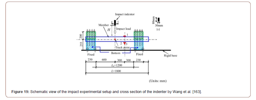
Wang et al. [162] implemented an experimental study on FRP-Concrete-Steel double skin tube members subjected to lateral impact loading. Furthermore, the composite design of the structural member consisted of an outer FRP tube and inner steel tube with concrete fill between the circular tubes. In addition, Figure 19 shows the schematic view of the impact experimental setup and cross section of the indenter. Besides, the experimental investigation consisted of 24 specimens tested under lateral impact load to determine (1) lateral deflections, (2) impact forces-time histories, strain and failure modes. In addition, the tested specimens had variables such as, number of FRP layers (0, 1, 2 and 3 layers) and impact load velocity. Finally, Wang et al. [162] found that as the number of outer FRP layers increases, the impact resistance of FRPConcrete- Steel double skin tubular member’s increases. Generally speaking, FRP-Concrete-Steel double skin tubular members performs in a ductile form under lateral impact loads (Figure 19).
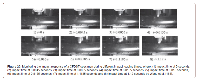
Wang et al. [162] did an experimental investigation on 31 concrete filled double steel tubular (CFDST) members subjected to low velocity impact load. Moreover, two types of columns were tested, these are, straight columns and tapered columns. In addition, the tested CFDST specimens had various other variables. For example, simply supported/fully fixed boundary conditions, level of axial load and magnitude of impact energy. Furthermore, Figure 20 shows the tracing of impact response of a CFDST specimen during different impact loading times. While Figure 21 presents the failure modes in mid-span of CFDST specimens after lateral impact loading. It was determined, that (CFDST members behaves in a ductile manner under lateral impact, (2) the impact energy absorption rate for CFDST specimens is higher than hollow double steel tubes by 1.2 up to 1.9 times more, (3) as the magnitude of impact energy increases, the global deformation increases and (4) Fixed-fixed boundary condition support has lower local deformation under lateral impact than rotational restraint boundary condition supported specimens (Figures 20,21).
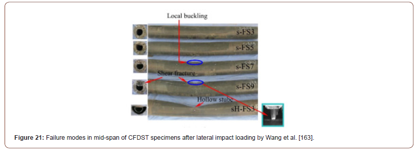
Wang et al. [128] did numerical simulations on the response of concrete filled double skin steel tubes (CFDST) members subjected to low velocity lateral impact loading. Moreover, Wang et al. [128] used existed experimental results to validate the numerical models. In addition, Figure 22 illustrates a numerical model and cross section of CFDST simply supported at both ends and subject to lateral impact load induced by a hammer. Furthermore, the validation was followed by a parametric analysis with 5 different variables. These are (1) height of impact load, (2) ratio of hollow steel tube, (3) ratio of steel, (4) the ratio of inner steel diameter-tothickness and (5) material strength and its properties. Moreover, the variation in results between the parametric variables were used to determine the global residual lateral deformation (Gres) under impact loading. Based on the results, Wang et al. [128] has determined the below:
1. The global lateral deformation and the resistant value plateau are majorly affected by the steel ratio, concrete strength and steel tubes yield stresses.
2. The peak force impact value is majorly affected by the ratio of the tube hollow section (Figure 22).
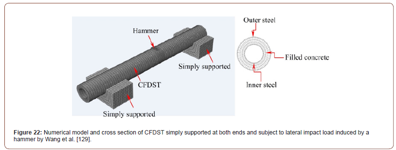
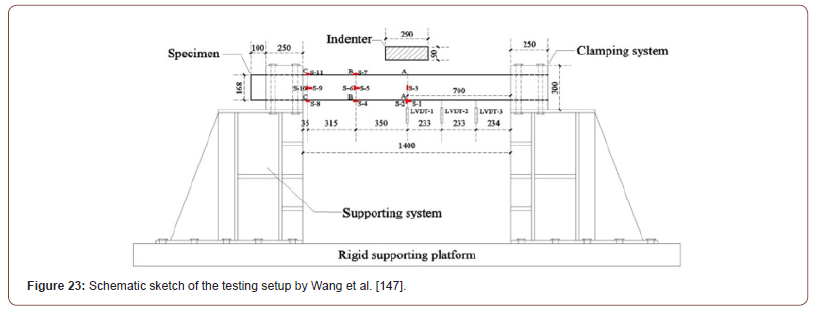
Wang et al. [163] did an experimental and numerical analysis on Ultra-High-Performance Fiber-Reinforced Concrete (UHPFRC) filled steel tubes subjected to lateral impact load. In addition, five samples were tested under lateral impact (Three UHPFRC) and Two Normal Strength Concrete (NSC) filled steel tubes. Moreover, Figure 23 shows a schematic sketch of the testing setup. Furthermore, two variables were analyzed (1) singular skinned CFST and double skin CFST and (2) impact energy load and (3) UHPFRC/NSC. Moreover, Wang et al. [163] determined the below:
1. UHPFRC filled steel tube has greater lateral impact resistance, greater peak, lower local indentation, and fewer deflection than NSC filled steel tubes.
2. As the impact energy load increases, the UHPFRC filled steel tubes experiences more deflection. However, the plateau impact force stays uninterrupted.
3. Double skin UHPFRC filled steel tubes does not reduce the lateral impact resistance (Figure 23).
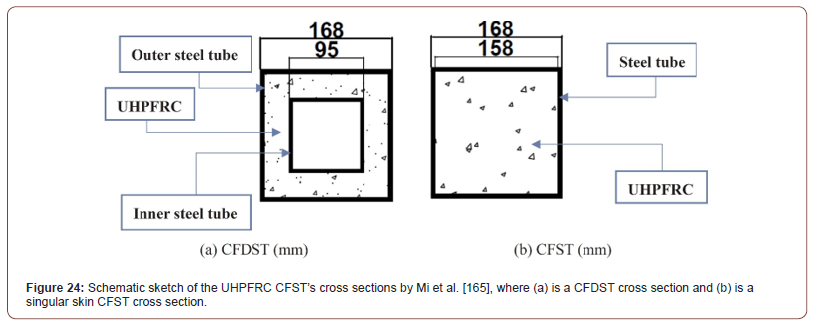
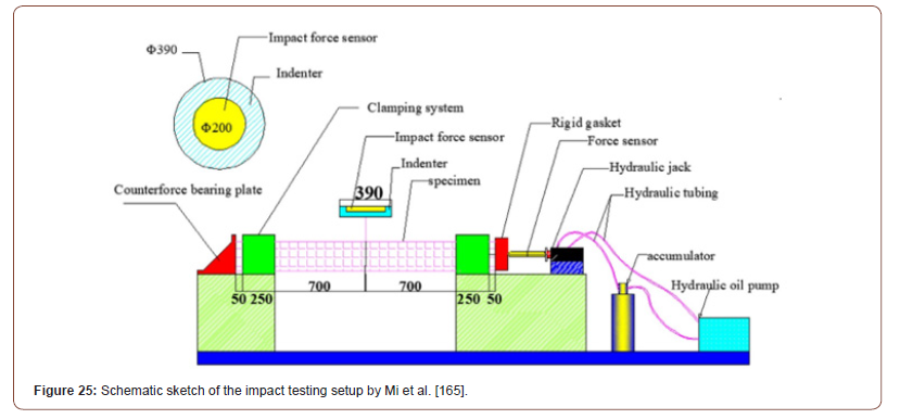
Mi et al. [164] did an experimental investigation on ten CFST samples to determine the residual axial bearing capacity (Rabc) under lateral impact load. Besides, the ten CFST samples consisted of seven Concrete-Filled Double-skin steel tubes (CFDST) and three normal single skin CFST samples. Consequently, Figure 24 shows the cross sections of double skinned CFST and singular skin CFST. Whereas Figure 25 illustrates the transverse impact load testing setup. Furthermore, the study included six major parameters (1) type of concrete, (2) ratio of steel, (3) form of section, (4) ratio of axial load, (5) impact energy and (6) subjected or not subjected to impact loading. Finally, Mi et al. [164] has observed the below:
1. The residual performance of CFST under impact load increases as the steel ratio/tube thickness increases.
2. By using Ultra-High-Performance Fiber-Reinforced Concrete (UHPFRC) the bearing capacity of non-impacted samples increases by 47.1% when compared with specimens filled with Normal-Strength Concrete (NSC).
3. Using Ultra-High-Performance Fiber-Reinforced Concrete (UHPFRC) fill in CFST columns improves the residual performance significantly (Figures 24,25).
Concrete Filled Stainless Steel Tubular (CFSST) structural elements subjected to lateral/transverse impact load
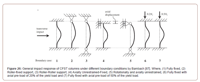
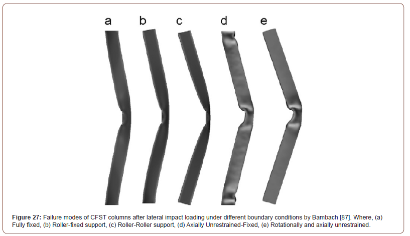
Bambach [86] conducted experimental and numerical analysis on hollow and CFST columns tested under transverse impact loads. In the study, two different tubular steel materials were used. The first one was mild steel and the second was stainless steel. Besides, the material properties for the tested mild steel and stainless steel have been shown in Table 1. Moreover, the specimens were restrained rotationally and axially at the top and bottom ends. Furthermore, the global performance and the absorbed energy of the CFST columns were analyzed. In addition, various variables were studied to determine their influence on impact behavior. For example, the variables were (1) steel material properties, (2) infilled concrete and (3) boundary conditions. Additionally, the general impact response of CFST columns under different boundary conditions has been presented in Figure 26. While Figure 27 demonstrate the failure modes of CFST columns after lateral impact loading under different boundary conditions. Besides, the main objective of the research was to investigate the transverse impact energy absorption capacity of CFST columns in relation to the above-mentioned variables. Finally, Bambach [86] has drawn the below conclusions:
1. CFST columns decreases the capability of impact energy absorption when compared with hollow steel tubes.
2. Stainless steel tubes perform better and has higher impact load bearing capacity than the classical normal steel. Besides, the impact absorption rate of stainless steel is 1.8 times higher than normal mild steel. This has been clarified due to the higher characteristics and material properties, such as strain failure.
3. Axially restrained specimens have showed the highest energy absorption capacity by creating a tensional mechanism (Table 1) (Figures 26,27).
Table 1:Material properties for steel and stainless-steel tubes by Bambach [87].


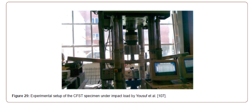
Yousuf et al. [106] has mentioned that the material characteristics of stainless-steel tubes varies from those of mild steel tubes. The features vary in corrosion resistance, ductility and strength. Thus, Yousuf et al. [106] studied the response of hollow stainless-steel tubes and CFST columns subjected to static and impact loads. Furthermore, the weight of the drop hammer was 592Kg and a drop height of 650mm with a potential energy of 3775J. Figures 28 & 29 illustrates a schematic drawing and experimental setup of the impact testing respectively. At the end, Yousuf et al. [106] has found that concrete filled stainless steel has higher ductility, more strength and increases the impact resistance of CFST against local buckling (Figures 28,29).
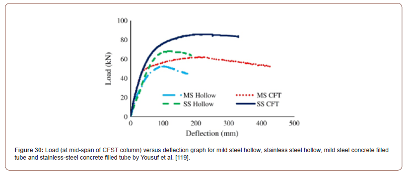
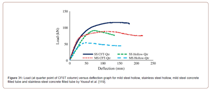
Yousuf et al. [118] did an experimental study on 16 hollow and concrete filled steel columns subjected to static and dynamic impact loads. Moreover, the investigation included monitoring the variance in behavior between mild steel and stainless-steel tubes. In addition, the CFST were subjected to static and dynamic impact loads at the quarter point and mid-span of the columns. Besides, Figure 30 shows load versus deflection graph at mid-span of CFST column. While Figure 31 represents load versus deflection graph at quarter point of CFST column for (1) mild steel hollow, (2) stainless steel hollow, (3) mild steel concrete filled tube and (4) stainless steel concrete filled tube. Furthermore, the main aim of the conducted research by Yousuf et al. [118] was to find the best dynamic impact load performance of CFST using mild steel, stainless steel, hollow and concrete filled columns. Yousuf et al. [118] has found that using stainless steel tubes increases the global impact resistance of CFST columns and reduces buckling. In addition, CFST columns had lower maximum deflection under impact load when compared to hollow tubes (Figures 30,31).
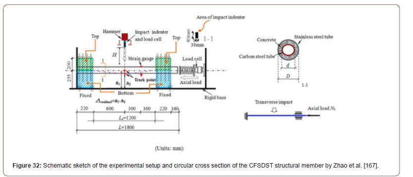
Feng et al. [165] tested 36 circular stainless-steel tubes under in-plane bending. Moreover, the specimens had two variables, for example, the first variable was between hollow and concrete filled stainless steel tubes and the second variable was bare/ unstrengthen specimens and CFRP strengthened specimens. Furthermore, the study focused on determining the flexural behavior of the specimens under in-plane bending. It was observed that (1) CFRP reinforced samples has increased the strength ratio, (2) by applying more CFRP reinforcement layers on the tested specimens, the ultimate strength increases and (3) by filling the circular hollow section (CHS) stainless steel tubes with concrete, the flexural stiffness and strength is improved. Zhao et al. [166] performed experimental and numerical simulations on the impact load behavior of circular concrete filled double skin tube members using external stainless-steel tube and internal carbon steel tube. Moreover, eighteen samples were prepared and evaluated under axial load and impact load with three testing variables. For instance, height of impact load, ratio of hollow steel tube and magnitude of axial load). Besides, Figure 32 displays the Schematic sketch of the experimental setup and circular cross section of the CFSDST structural member by Zhao et al. [166]. After testing the specimens, the results were gathered including failure modes, mid-span deflection, impact load time histories and strain in stainless steel. Finally, Zhao et al. [166] has found that (1) the plateau impact force decreases as the ratio of hollow steel tube and level of axial load increases, (2) as the level of axial load and impact load increases, the residual deflection in mid-span of the specimens increases, (3) by using external stainless-steel tubes, the impact resistance of CFSDST structural member is higher compared with external carbon steel tubes (Figure 32).
High Strength Concrete-Filled Steel Tubular (HSCFST) structural elements subjected to lateral/transverse impact load
Wu et al. [167] did experimental and numerical analysis on the performance of ultra-high cementitious composites filled steel tubes under transverse low-velocity impact load. Moreover, the specimens were tested under three variable drop-hammer releases heights, for instance, 5, 8 and 11m drop heights. Furthermore, the deflection-time and impact force results data were analyzed. It was observed that UHPCC-FST specimens behaves in a ductile form and has high impact resistance against transverse low-velocity impact loading. In addition, the steel tubes did not experience major local buckling and UHPCC concrete core controlled efficiently the indentation surrounding the area of impact and reduced the deflection in the steel tube. Also, Wu et al. [167] has determined that the residual deflections and maximum impact force increases as the drop-hammer release height increases. Yang et al. [168] has experimentally tested eighteen square specimens using normal-/high- strength steel tube columns infilled with high-strength concrete. Moreover, the samples were subjected to transverse impact load. Furthermore, the transverse impact load was generated HSCFST by a drop hammer with indenter to obtain the deformation, impact force and energy absorption of the tested specimens. Yang et al. [168] has observed that the impact resistance has been greatly improved when using high strength grade S690 steel. However, due to the yield stress increment filling the CFST columns with high strength concrete did not have any major contribution in improving the impact resistance. Generally speaking, HSCFST columns behaves well under impact loading by (1) increasing the impact resistance, (2) have high impact force plateau value and (3) lower deformations.
Concrete Filled Steel Tubular (CFST) structural elements strengthened with Fiber Reinforced Polymer (FRP) subjected to lateral/transverse impact load
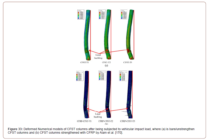
Alam et al. [169] did a numerical analysis to investigate the vehicle impact behavior improvement on CFST columns strengthened with CFRP. To achieve this, Alam et al. [169] carried out the numerical investigation on full scale bare CFST columns and CFST columns strengthened with CFRP. Moreover, Figure 33 shows the deformed Numerical models of bare/unstrengthen CFST columns and CFRP strengthened CFST columns after being subjected to vehicular impact load. Accordingly, it was observed that the adhesively bonded CFRP sheets to CFST columns has (1) increased the impact resistance capacity, (2) decreased the lateral deformation by 40% and (3) prevents the global failure of CFST columns under vehicular impact (Figure 33).
Shakir et al. [170] conducted experimental study to investigate the lateral impact behavior of circular CFST columns strengthened with CFRP and bared/unstrengthen specimens. Furthermore, Figure 34 shows the experimental testing setup of a CFST structural member under lateral impact loading. Besides, 84 specimens were tested with four analyzed variables. The variables were (1) the length of the steel tube, (2) the type of concrete fill, for instance, Normal Aggregate Concrete (NAC) / Recycled Aggregate Concrete (RAC), (3) impactor configuration and (4) strengthened with CFRP and bared/unstrengthen specimens. Furthermore, Shakir et al. [170] has concluded that the type of concrete fill (NAC or RAC) are almost the same in terms of the geometry of the deformation and the impact resistance of the tested samples are also more or less the same for both NAC and RAC fills. Also, it was found that the global displacement and total indentation resistance increases remarkably when filling the hollow circular steel tubes with concrete. In addition, it was obvious from the results that when strengthening the CFST with CFRP, the impact resistance increases against global deformation. For example, when installing one layer of CFRP on the CFST column members, the global deformation reduces by 62% and 8.3%. Likewise, Figure 35 demonstrates a schematic drawing of the deformation measurements of the CFST after being subjected to lateral impact loading. The deformation measurements were the total displacement, global displacement and indentation (Figures 34,35).

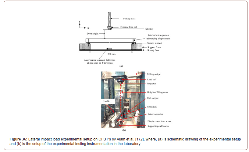
According to Alam et al. [171] strengthening CFST structural members with FRP reduces the damage or global failure created by impact loading. Moreover, sixteen CFST specimens (13 FRP reinforced specimens and three bare/unstrengthen specimens) were prepared and tested experimentally with a drop hammer. Besides, Figure 36 shows the lateral impact load experimental setup on CFST’s by Alam et al. [171]. Furthermore, the CFST members were wrapped with Carbon Fiber Reinforced Polymer (CFRP) and Glass Fiber Reinforced Polymer (GFRP). In addition, the specimens had variation in the number of FRP wrapped layers, for example, one, two and three layers were installed. This was performed to examine the effect of increasing the number of FRP layer on the impact resistance ratio of CFST members. Finally, the below conclusions were determined by Alam et al. [171]:
1. By strengthening the CFST members with 3 layers of CFRP membranes, the residual lateral displacement decreases by up to 18% when compared with bare/unstrengthen CFST specimens.
2. All CFST specimens has experienced global deformation failure mode.
3. By wrapping the CFST members with CFRP, the failure and cracks of infilled concrete core reduces.
4. The failure of CFRP laminates due to impact load can be reduced by wrapping CFST specimens with GFRP layers or with a wrapping combination of GFRP and CFRP.
5. The thicker the CFRP wrapping layer, the lower the lateral peak displacement in CFST specimens.
6. Strengthening CFST members with GFRP performs better than CFRP under lateral impact load (Figure 36).
He & Chen [172] experimentally analyzed the axial compression behavior of 27 circularly sectioned Glass Fiber Reinforced Polymer (GFRP) tubes filled with concrete and with an embedded u-shaped steel channel. Hence, the cross section of the GFRP tube filled with concrete with an embedded steel channel has be presented in Figure 37. Moreover, He & Chen [172] has examined three major variables to understand their structural performance under axial compression loads. Besides, the variables were, (1) the ratio of embedded u-shaped steel channel, (2) diameter-to-thickness ratio of outer GFRP tube and (3) the grade of concrete strength. Furthermore, He & Chen [172] has found that the initial stiffness and deformation capacity of the specimens increases as the concrete strength increases. Finally, both the ratio of embedded u-shaped steel tube channel and diameter-to-thickness ratio of outer GFRP tube had a negative correlation on the axial deformation properties and restraint effect respectively (Figure 37).

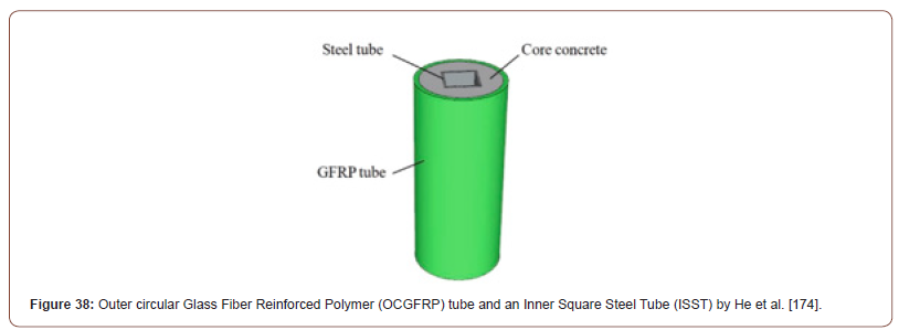
He et al. [173] conducted experimental and numerical analysis on 27 concrete filled GFRP tubular hollow composite columns subjected to axial compression load. Moreover, an innovative design was conducted by He et al. [173] which consisted from an outer circular Glass Fiber Reinforced Polymer (GFRP) tube and an Inner Square Steel Tube (ISST) as shown in Figure 38. Furthermore, the tested specimens under axial compression loading were investigated to determine the ultimate bearing capacity, modes of failure and relation between load and displacement. Besides, three parametric variables were simulated, such as, ratio of hollowness (Ψ), GFRP outer tube diameter to thickness ratio and concrete compressive strength. Finally, He et al. [173] concluded the below:
1. As the hollowness ratio (Ψ) increases, the ultimate bearing capacity of GFRP tubular columns decreases.
2. As the GFRP outer tube diameter to thickness ratio increases, the ultimate bearing capacity decreases.
3. As the concrete strength increases, the ultimate bearing capacity increases (Figure 38).
Reinforced Steel Concrete Filled Steel Tubular (RSCFST) structural elements subjected to lateral/transverse impact load
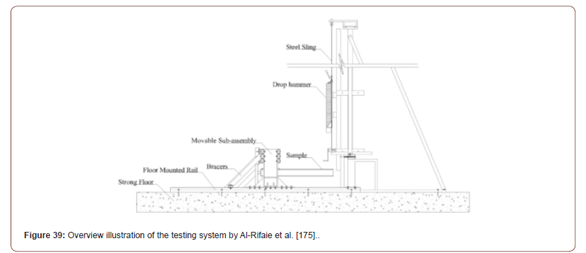
To increase the load-bearing capacity of CFST columns under various loads, such as, fire and cyclic loads, Romero recommended the installation of advanced material to CFST columns and their fixtures. Furthermore, the suggested advanced materials were (1) high strength steel – HSS, (2) geo-polymer concrete fill, (3) blind-bolts and blind-bolted connections and (4) shape memory alloys (SMA). Al-Rifaie et al. [174] experimentally and numerically tested eight CFST columns with end plated connections. According to Al-Rifaie et al. [174] there is missing literature in studying the impact behavior of CFST connected to an I-steel beam. Therefore, Al-Rifaie et al. [174] has used two types of connections which fixes the CFST column with I-steel beam. Moreover, Figure 39 shows the overview illustration of the testing system Furthermore, five samples were structured using Partial Depth End Plate Connection (PDEPC) and four specimens were constructed using Flush Plate Connection (FPC). Besides, the plate connection thicknesses were 8 and 15mm, joining the CFST column and I-steel beam using long bolts. In addition, the specimens were subjected to impact load at two different load locations. The major finding was as follows:
2. The moment capacity increases when using thicker endplate connection.
3. The ductility rate is maintained until failure when using long bolts (Figure 39).
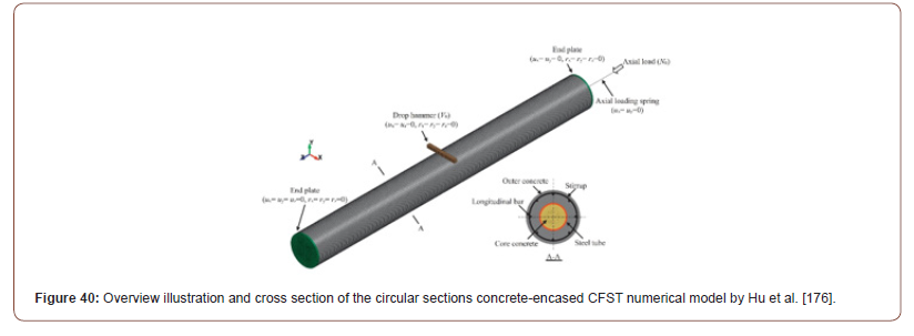
Hu et al. [175] conducted a numerical analysis on eleven circular sections concrete-encased CFST models subjected to laterally low velocity impact load with a range from 2m/s to 12m/s. Likewise, Figure 40 presents an overview illustration and cross section of the circular sections concrete-encased CFST numerical model by Hu et al. [175]. Moreover, the loading condition considered a combination outcome of both lateral impact load and axial load. Additionally, the numerical models were subjected to various impact force versus impact time to record the mid-span deflection versus time. Furthermore, the results obtained from the numerical analysis were compared with other experimental results in terms of impact resistance and global behavior. Besides, Hu et al. [175] has concluded that concrete encased composite CFST structures has higher impact resistance than reinforced concrete and typical CFST structural members. In addition, the impact resistance of CFST members increases with (1) higher steel strength, (2) higher thickness steel tubes and (3) larger diameter steel tubes. Also, the concrete strength class and ratio of internal reinforcement steel bars in the concrete core of the CFST enhances in increasing the dynamic flexural capacity (Figure 40).
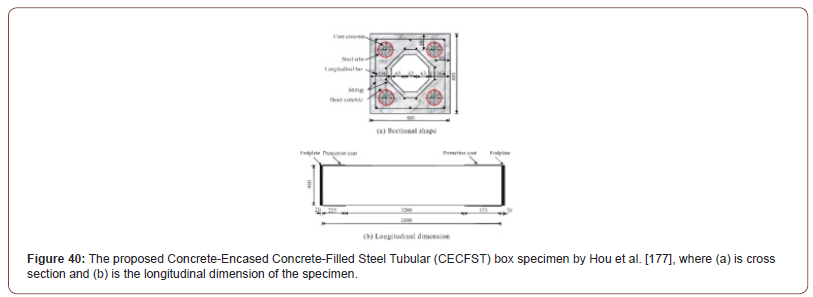
Hou et al. [176] conducted experimental and numerical analysis on twenty Concrete-Encased Concrete-Filled Steel Tubular (CECFST) box specimens to evaluate their structural response after being subjected to lateral impact loading. Moreover, the specimens were tested under three different variables (1) magnitude of impact energy, (2) magnitude of axial load and (3) boundary conditions. It was found that the Reinforced Concrete (RC) had the highest impact resistance and protected the embedded CFST parts of the structural member. Finally, but never the least, Hou et al. [176] mentioned that the proposed composite design as shown in Figure 41, is safer and is easier for maintenance purposes after the event of impact loading (Figure 41).
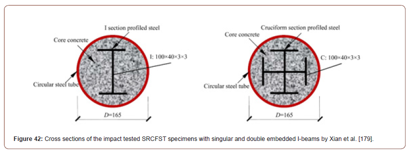
Xiang et al. [177] did impact loading experimental analysis on the dynamic response of T-shaped steel reinforced concrete columns. Besides, the specimens were axially loaded during the impact testing. However, Xiang et al. [177] did not cover the reinforced columns with outer steel tubes. Xian et al. [178] did an experimental study on eighteen Steel-Reinforced Concrete-Filled Circular Steel Tubes (SRCFST) subjected to lateral impact loads. Moreover, the CFST were internally reinforced with I-beams in the concrete core of the specimens. Besides, Figure 42 presents the cross sections of the impact tested SRCFST specimens with singular and double embedded I-beams by Xian et al. [178]. Afterwards, a drop hammer impact testing system was applied on the samples to represent the impact load. It was determined that SRCFST structural members has high impact resistance and has the ability to absorb high impact energy. Additionally, the results showed that the fixed-fixed boundary conditions for SRCFST have the highest impact resistance performance and reduces the mid-span deflection (Figure 42).
Partially Concrete-Filled Steel Tubular (PCFST) structural elements subjected to lateral/transverse impact load
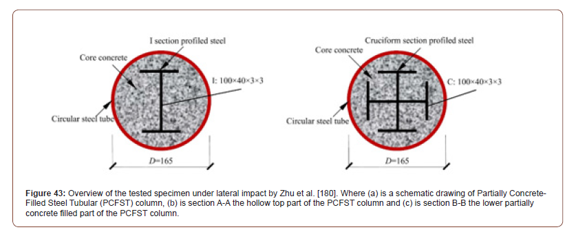
Zhu et al. [179] conducted experimental and numerical analysis on 12 rectangular shaped CFST column specimens (nine Partially Concrete-Filled Steel Tubular (PCFST) columns and three Rectangular Hollow Steel Tubular (RHST) columns subjected to lateral impact. As such, Figure 43 presents a schematic sketches of the Partially Concrete-Filled Steel Tubular (PCFST) column and its hollow and concrete filled sections. Besides, the study considered three main variables. Furthermore, the variables were, the height of the concrete fill, lateral impact energy and direction of the impact. Moreover, Zhu et al. [179] concluded that PCFST specimens had greater impact resistance behavior than RHST specimens. In addition, there was a direct relation between the mode of failure and the height of the concrete fill. Moreover, the lateral impact energy and the direction of the impact load plays an important role in identifying the impact resistance of PCFST columns (Figure 43).
Pre-casted segmental CFST under impact loads
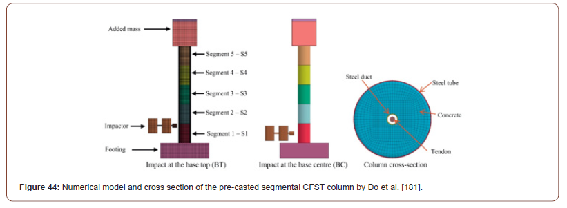
Do et al. [180] has investigated numerically the response of pre-casted steel columns and CFST columns under different impact loads. Moreover, the impact load was applied on two different locations (Mid-span and top quarter side of the CFST column). In addition, Figure 44 demonstrates the numerical model and cross section of the pre-casted segmental CFST column by Do et al. [180]. Furthermore, Do et al. [180] has determined that by covering the pre-casting concrete columns with steel tubes, the rate of impact resistivity increases and alter the impact response positively (Figure 44).
Concrete Filled Steel Tubular (CFST) structural elements subjected to blast loads
Zhang et al. [181] did numerical modelling and analysis on circular and square CFST sections subjected to both static and blast loads. Additionally, Zhang et al. [181] concluded that the local deformation in steel tubes after blast loading is eliminated when filling the hollow steel tubes with concrete. Moreover, the blast energy is absorbed by the global deformation of the CFST structural member. Zhang et al. [182] has experimentally tested eight concrete-filled double skin steel tubular column specimens (three square sections and five circular sections) under various close-in blast loading and two axial loads with different magnitudes. Moreover, the CFDST column specimens were infilled with ultra-high-performance fiber reinforced concrete (UHPFRC). It was concluded that (1) CFDST column specimens filled with UHPFRC performs better and has higher blast resistance capacity than CFDST column filled with normal concrete, (2) CFDST column specimens which had greater peak residual axial capacity (Prac) has experienced lower permanent displacement and (3) the ductile response of CFDST samples was higher for the specimens which were not axially loaded at the time of blast load testing. With reference to Zhang et al. [132], many investigations have been done on testing concrete-filled double-skin tubes (CFDST) subjected to various load condition types. Accordingly, Zhang et al. [132] conducted experimental study to test CFDST columns infilled with ultra-high-performance concrete under close-in blast loads. Moreover, the investigation considered two different types of CFDST with (1) circular tube with inner circular tube and (2) outer square tube with inner square tube. Furthermore, the testing had two variables (axial load magnitude and explosive weight). In addition, the results have showed no failure in the steel tubes such as ruptures or buckling. Besides, the concrete core had very small cracks with a width not exceeding 1mm. As such, Zhang et al. [132] has proofed that CFDST columns performs very efficiently under blast loads and has high blast resistance. Wang et al. [183] has experimented the blast resistance and residual strength capacity of four CFST columns with circular section and four CFST columns with square section subjected to close-range blast loading and static axial load. Moreover, two types of testing equipment’s were used to measure the displacement and the pressure, these were (1) Linear Variable Differential Transformer (LVDT) and (2) pressure sensors respectively. Furthermore, Wang et al. [183] has analyzed the various behaviors of the specimens by considering three main variables in the experimental study (Explosive charge weight, thickness of steel tube and the geometry of the cross section). Finally, but never the least, Wang et al [183] has observed that the maximum displacement in mid-span increases as the explosive charge weight increase. Also, the maximum displacement in the mid-span decreases as the thickness of the steel tube increases. In addition, it was found that the circular geometric sections behave better than square geometrical sections under blast loads. Zhang et al. [135] did experimental and numerical investigation to find the response of square sectioned Ultra-High-Performance Concrete (UHPC) filled double skin steel tube columns under close-range blast loading. In addition, a parametric analysis was performed by Zhang et al. [135] to determine the blast response of CFDST with different parameters. It was determined that the proposed and tested CFDST can sustain high blast loads without failure. Additionally, the tested CFDST specimens did not experience any concrete crushing nor steel buckling. Also, it was concluded that the geometry of the out-steel layer plays an important role in the blast behavior of CFDST. Whereas the geometry of the inner steel tube did not show any significance in increasing the blast resistance of CFDST specimens.
Ritchie et al. [184] conducted a real case situation blast loading in a large-scale field on CFST rectangular shaped specimens. Moreover, the steel tubes were cold-formed, and the field analysis was carried out on both filled and hollow steel tubes. It was observed that CFST performed better than the rectangular hollow steel tubes in terms of resistivity and had lower global displacement. In addition, the concrete filled rectangular steel tubes did not show any local buckling in steel after the event of blast load. While the unfilled rectangular hollow steel tubes had local buckling and high plastic rotation capacity. Li et al. [185] conducted experimental and numerical simulations on circular sectioned concrete-filled double-skin steel tube columns (CFDST) to investigate their response after exposed to close-in blast loading. Furthermore, the experimentally tested samples have suffered from major damages in the concrete core. On the other hand, the outer steel tubes did not experience any damage after the blast load. This mechanism was justified by Li et al. [185] due to the low energy absorption rate of the concrete core during blast loading. Zhang et al. [186] has investigated numerically the blast load behavior of CFST segmental columns. Furthermore, three CFST segmental columns consisting of three different segments. The first model had three segments, while the second and the third models had five and seven segments respectively. Moreover, Zhang et al. [186] has applied four blast loads on the models with various TNT weights (5Kg, 20Kg, 35Kg and 50Kg). In addition, a parametric study was performed on different concrete infilled strengths, thickness of steel tube, pre-stress ratio to determine the influence of those factors on the performance of CFST segmental columns under blast loads. It was concluded that the below factors had improved the blast resistance of CFST segmental columns:
1) Increasing the thickness of steel tube.
2) Increasing the number of segments in the CFST columns.
3) Using concrete filling with higher strength.
4) Increasing the pre-stress force.
Methodologies used by Past Research
This section of the literature review describes the methodologies used by past research and it consists of two parts. Whereas, the first part presents the geometrical properties, type of analysis, material properties cross sectional dimensions and boundary conditions of CFST’s of previous research. While the second part discusses numerical mesh and elements conducted by previous researchers.
Geometrical properties, type of analysis, material properties, cross sectional dimensions and boundary conditions of CFST’s of previous research
The geometry of sections, type of steel tube, type of study (weather experimental or numerical), type of analysis, type of steel, concrete fill properties, CFRP properties, dimensions, thickness of steel tube and boundary condition for previous researchers has been presented in Table 2. As can be seen in Table 2, the researchers have investigated diverse types of geometrical properties, various types of material properties and with different dimensions and boundary conditions (Table 2).
Table 2:Geometrical properties, type of analysis, material properties cross sectional dimensions and boundary conditions of CFST’s of previous research.

Numerical mesh and elements
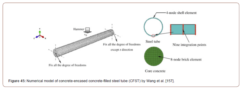
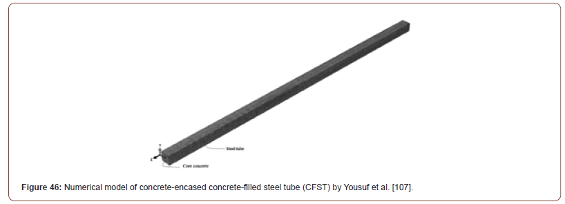
Many different types of meshing and elements has been simulated for CFST structural members using various Finite Element Analysis applications. However, in this section only the most appropriate meshes and elements will be briefly discussed. Also, all the below presented literature of the meshing and elements of the previous research has conducted a mesh convergence studies to determine the most suitable mesh density. Wang et al. [156] has used ABAQUS/Explicit module Finite Element Analysis software to model CFST and determine their structural response after being subjected to lateral impact loading. Moreover, the concrete core fill was built using “8-node brick elements with reduced integration”. However, the steel tube was modelled using “4-node shell elements with reduced integration”. Furthermore, the meshing and elements simulation which was used for the drop hammer was 4-node rigid shell element. In order to avoid zero energy modes, the chosen type of stiffness was hourglass. Additionally, the steel type has a nine integration points including the thickness of the tube. Besides, Figure 45 shows the numerical model of concrete-encased concrete-filled steel tube (CFST) by Wang et al. [156] (Figure 45). Yousuf et al. [106] has used ABAQUS Finite Element Analysis software to numerically analyze CFST by simulating 8-node brick elements (C3D8R) for concrete and steel tube. Moreover, each node had three translational degrees of freedom as illustrated in Figure 46 (Figure 46).
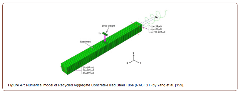
Yang et al. [158] has developed a numerical RACFST (Figure 47) model using ABAQUS Finite Element Analysis software to investigate the lateral impact load response. Besides, a threedimensional shell element (S4R) and a 4-node reduced-integration was simulated for the steel tube. While the concrete core fill was built using “8-node reduced-integration three-dimensional brick elements (C3D8R)”. Moreover, the drop weight had a rigid surface and simulated as a three-dimensional rigid element (R3D4) with 4-node (Figure 47).
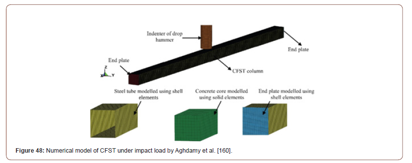
Aghdamy et al. [159] did a numerical modelling of CFST structural members using LS-DYNA MAT072R3 Software as shown in Figure 48. Moreover, the mesh properties were modeled as below:
1. Steel tube (4-node quadrilateral thin shell elements with Belytschko–Tsay formulation)
2. Concrete core (Single point integration and 8-node hexahedron“constant stress”solid elements)
3. Indenter (Single point integration and 8-node hexahedron“constant stress”solid elements)
4. End plates (4-node quadrilateral thin shell elements with Belytschko–Tsay formulation)
Additionally, five integration points were used for shell elements including thickness (Figure 48).
Wang et al. [128] analyzed Concrete Filled Double Skin Steel Tubes numerically using ABAQUS Finite Element Analysis software. Moreover, the numerical model was subjected to lateral impact. Besides, Figure 49 demonstrates the numerical model of CFDST under impact load by Wang et al. [128]. Additionally, the below configurations were simulated in building the meshing and elements:
1. Outer and inner steel tubes “nine integration points through the steel tubes thickness and 4-node shell elements.
2. Concrete fill sandwich between the outer and the inner steel tubes “8-node brick elements”
3. Drop hammer “4-node rigid shell elements”
4. Mesh elements “hourglass energy less than two percent of the overall impact energy”
5. The size of the smallest element edge was 5mm and the largest was 10mm (Figure 49).

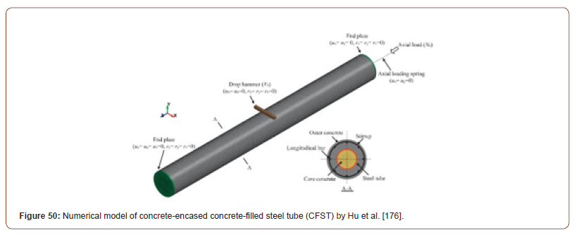
Hu et al. [175] build the numerical models of concrete-encased concrete-filled steel tube (CFST) members by using LS-DYNA Finite Elements Analysis software. The first step was carried out by assigning eight-node hexahedron with solid elements and one-point integration for the testing apparatus including the supports and the drop hammer. Moreover, four-node quadrilateral thin shell elements have been chosen for the steel tube. In addition, the Belytschko-Tsay formulation has been set for the steel tube with five integration points shell elements including the thickness. Furthermore, the internal reinforcement steel bars, stirrups and axial load (springs) had a cross section integration using Hushes-Liu formulation with two-node elements. Finally, to join the internal reinforcement steel bars and stirrups with the solid concrete elements Hu et al. [175] has chosen the command “Constrained Lagrange in Solid”. Figure 50 shows the numerical model of concrete-encased concrete-filled steel tube (CFST) by Hu et al. [175] (Figure 50).
Zhao et al. [166] has used ABAQUS commercial version to model Concrete Filled Double Skin Steel Tubes (CFDST) subjected to transverse impact loading on the mid-span of the specimens as shown in Figure 51. Besides, the meshes and elements properties of the numerical model are listed below:
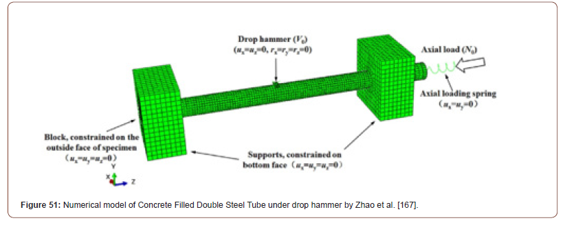
1. Steel tubes mesh simulated using S4R 4-node shell elements.
2. The mesh for concrete fill sandwich between the outer and the inner steel tubes was simulated using C3D8R 8-node solid element.
3. The mesh for drop hammer was built using R3D4 4-node quadrilateral rigid element (Figure 51).
Yang et al. [168] has modelled HSCFST (Figure 52) to study the behavior under transverse impact loading using ABAQUS/Explicit. Besides, the mesh for both the concrete core and the steel tube was built as below:
1. Control element type is hourglass
2. C3D8R solid element that is an 8-node linear brick
3. Reduced integration
However, the support testing setup and indenter of the drop hammer were simulated using 3-D bilinear rigid quadrilateral element (R3D4) with 4-node (Figure 52).
Past research loading conditions and testing results
The third section of this chapter presents the last research loading conditions and testing results and consists of four parts. Whereas the first part of this section discusses the past research loading conditions and result. While the second part of this section shows the failure modes of CFST’s of the previous studies. Furthermore, the third part of this section describes the impact force versus impact time for the tested CFST for the tested specimens by previous studies. Nevertheless, the fourth part of this section focuses on discussing the mid-span deflection versus impact time and residual displacement.
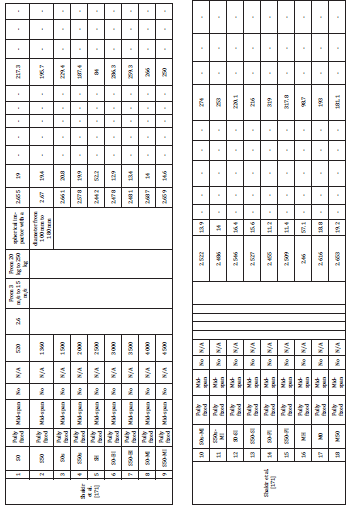
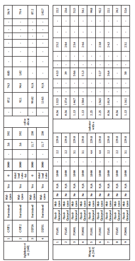
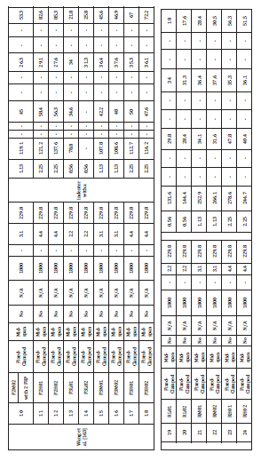
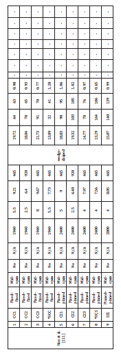
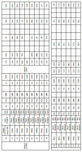
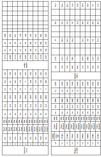
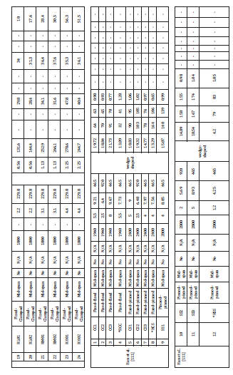
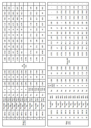
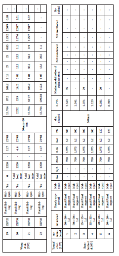
Past research loading conditions and results: The specimens label tag numbers, boundary conditions, location of impact loading, magnitudes of axial loading, specimen’s lengths, impact load drop heights, impact load velocities, impact load mass, geometry and size of indenters, impact energy, maximum displacements, impact times, plateau values of impact forces and residual displacements for previous researchers has been presented in Table 3. As can be seen in Table 3, the researchers have investigated diverse type’s impact loading conditions (Table 3).
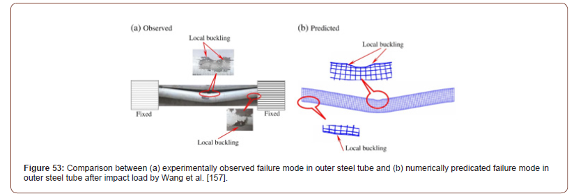
Failure modes: Wang et al. [156] has found that the outer steel tube locally buckles after being tested under impact load as demonstrated in Figure 53. Despite the fact that, the inner concrete fill core clearly had major failure modes such as concrete crush and cracks in the mid-span at the impact load point. In addition, tensile fracture was monitored a few centimeters away from the impact load at both right and left sides of the tested specimen as illustrated in Figure 54 (Figures 53,54).

On the contrary, the investigation by Yousuf et al. [106] focused on comparing the buckling behavior between hollow steel tubes and CFST under transverse lateral loading. As such, it was pragmatic that the buckling failure mode in the hollow steel tubes reduces when hollow steel tubes are filled with concrete as shown in Figure 55 (Figure 55).
Han et al. [110] has experienced two types of failure modes in the outer steel tube layer of the tested CFST specimens under lateral impact loading. Moreover, these failure modes in the outer steel tube layer were outward and inward buckling as shown in Figure 56. Similarly, the inner concrete fill core layer has experienced two types of failure modes after being subjected to lateral impact loading. These were (1) concrete crushing and (2) tensile cracks in the mid-span and both ends of the specimens as illustrated in Figure 57. Furthermore, Figure 58 demonstrates a comparison in the failure modes between the experimentally and numerical tested specimens after impact by Han et al. [110]. While Figure 59 presents the failure modes of the CFST numerically tested models after impact for the outer steel tube and the inner concrete core (Figures 56-59).
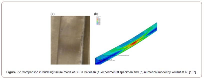
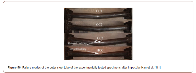
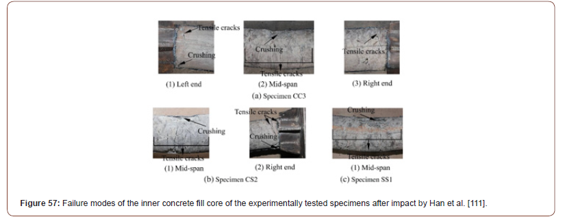
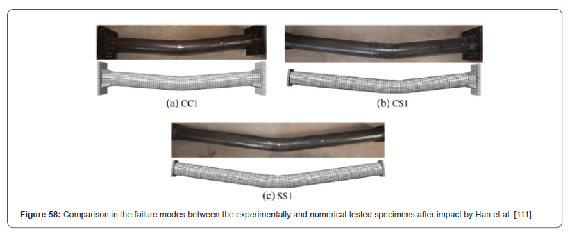
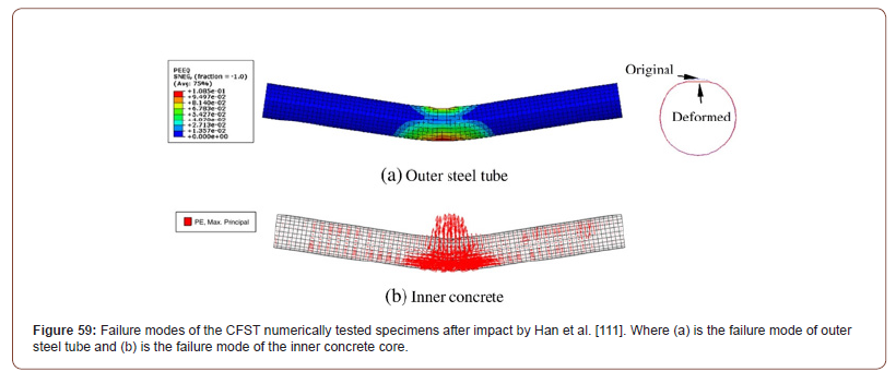
Table 3:Past research result of CFST’s subjected to lateral/transverse impact loading.
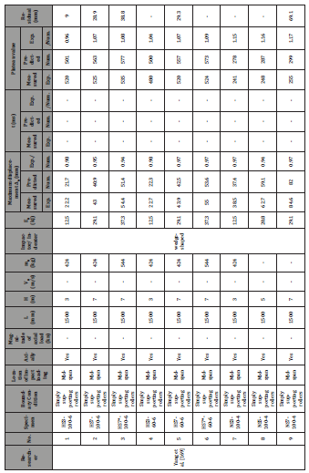
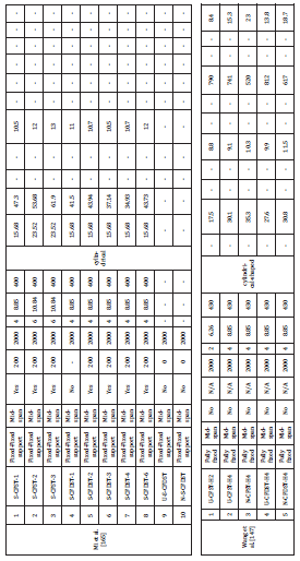
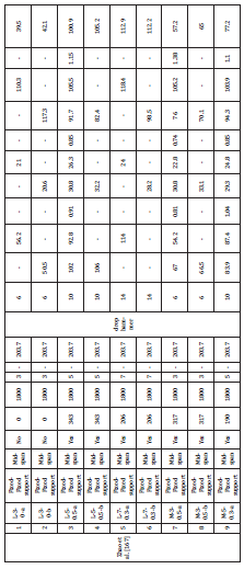


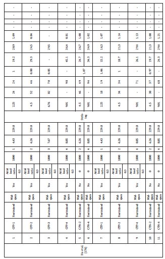


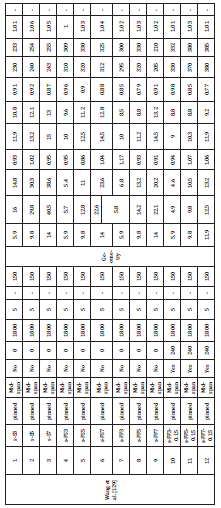
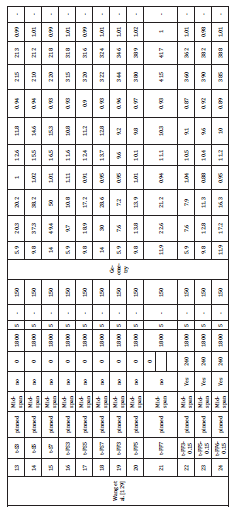

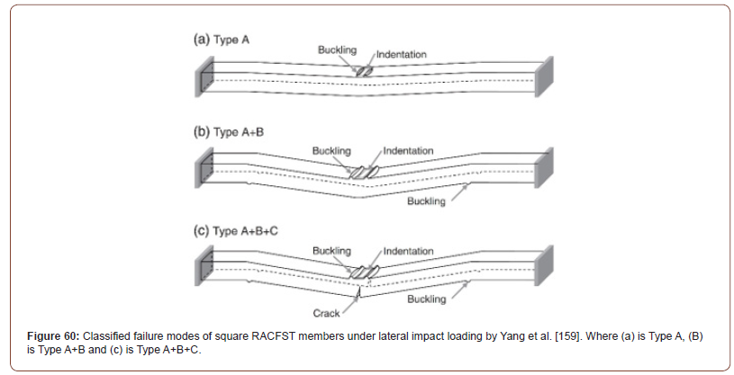
Yang et al. [158] has classified the observed failure modes of square RACFST members under lateral impact loading in to three classes. Moreover, the classified failure modes were (1) type A, (2) type A+B and (3) type A+B+C. Furthermore, type A had buckling and indentation at the lateral loading point in the mid-span of the tested specimen. Also type A+B had the same failure modes as type A, but with additional buckling at the right and left bottom soffit of the specimens away from the mid-span. Additionally, type A+B+C had all the failure modes of the two other types with an extra crack in the concrete infill core at the bottom mid-span soffit of the structural member as shown in Figure 60 (Figure 60).
As shown in Figure 61, Wang et al. [127] has reported the typical failure modes for different types of CFST’s under lateral impact loads. Where the typical failure modes for each CFST type are as below:
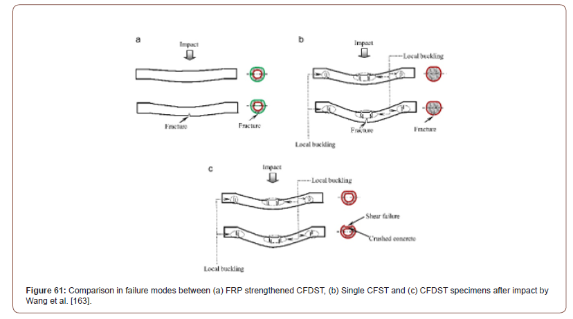
1. FRP strengthened CFDST (Fracture on the bottom soffit of the structural member)
2. Single CFST (Fracture on the bottom soffit of the structural member, local buckling on the upper soffit of the structural member and supporting sides.
3. CFDST (Shear failure on the top soffit of the outer steel tube, concrete crush of the concrete sandwich layer between the outer and the inner steel tubes and local buckling on the upper soffit of the structural member and supporting sides (Figure 61).
Shakir et al. [170] found that the CFRP strengthened CFST specimens had minor fracture and breakage modes of failure in the CFRP after impact loading. Moreover, some specimens had only 1mm CFRP fracture width as shown in Figure 62 (Figure 62).

Alam et al. [171] had CFRP fracture and breakage failure modes for CFST members strengthened with CFRP subjected to lateral impact as shown in Figure 63. It was noted that both, the compression and tension faces had fracture and breakage in the CFRP layer with variation in size (Figure 63).
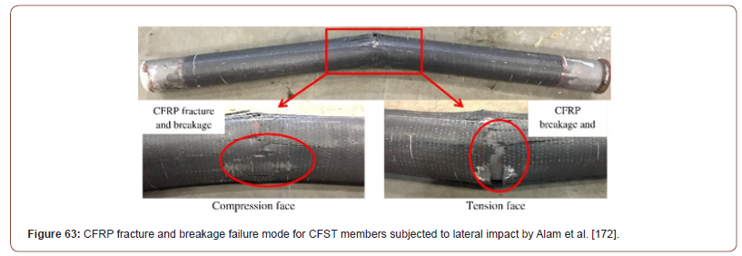
Hu et al. [175] has observed various failure modes in Concreteencased concrete-filled steel tube (CFST) after being subjected to lateral low velocity impact loading. Moreover, the outer steel layer has experienced local buckling in the mid-span. Whereas, the concrete fill core had concrete crush and concrete cracks, in addition to exposure to the internal reinforcement bars in the concrete core as shown in Figure 64 (Figure 64).
As can be seen from Figure 65, Zhao et al. [166] did a comparison between failure modes for specimens with different hollowness ratios (Ψ) and different drop heights. Moreover, a total of eighteen CFDST specimens were subjected to transverse impact loading with the below characteristics:
1. Six CFDST specimens had a hollowness ratio (Ψ) of 0.44 (two specimens were subjected to 3 meters impact load drop height, two specimens were subjected to 5 meters impact load drop height and two specimens were subjected to 7 meters impact load drop height).
2. Six CFDST specimens had a hollowness ratio (Ψ) of 0.69 (two specimens were subjected to 3 meters impact load drop height, two specimens were subjected to 5 meters impact load drop height and two specimens were subjected to 7 meters impact load drop height).
3. Six CFDST specimens had a hollowness ratio (Ψ) of 0.81 (two specimens were subjected to 3 meters impact load drop height, two specimens were subjected to 5 meters impact load drop height and two specimens were subjected to 7 meters impact load drop height).
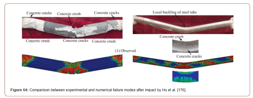
It was determined that as the hollowness ratio (Ψ) increases, the impact resistivity of the CFDST reduces. In addition, as the impact load drop height increases, the buckling in the inner and outer steel tubes increases. Also, all the CFDST specimens with a hollowness ratio (Ψ) of 0.44 sustained the transverse lateral loading with minor failure modes. Accordingly, CFDST specimens with tag numbers L-7-0.3-a and L-7-03-b with a hollowness ratio (Ψ) of 0.44 behaved in a ductile manner and had the highest impact resistivity after being subjected to transverse impact load from 7 meters drop height. For example, there no concrete crushing, nor concrete cracks after impact. However, CFDST specimens with tag numbers L-7-0.3-a and L-7-0.3-b under 7 meters impact load drop height had small size buckling in both outer and inner steel tubes. On the contrary, CFDST specimens with 0.69 and 0.81 hollowness ratios (Ψ) has been severely damaged with major concrete cracks, concrete crushing and high buckling and internal folding of both internal and external steel tubes under 7 meters impact load drop height. It is to be noted that specimens with tag numbers H-7- 0.5-a and H-7-0.5-b with 0.81 hollowness ratio (Ψ) under 7 meters impact load drop height has reached full failure. Figure 66 presents comparison between experimental and numerical failure modes for specimen with tag number L-7-0.3-b and specimen with tag number H-7-0.5-a by Zhao et al. [166]. While Figure 67 illustrates the failure modes of numerical model analysis for (1) the external stainless-steel tube, (2) concrete sandwich fill layer between the internal and external steel tubes and (3) internal carbon steel tube after being subjected to transverse impact loading (Figures 65-67).
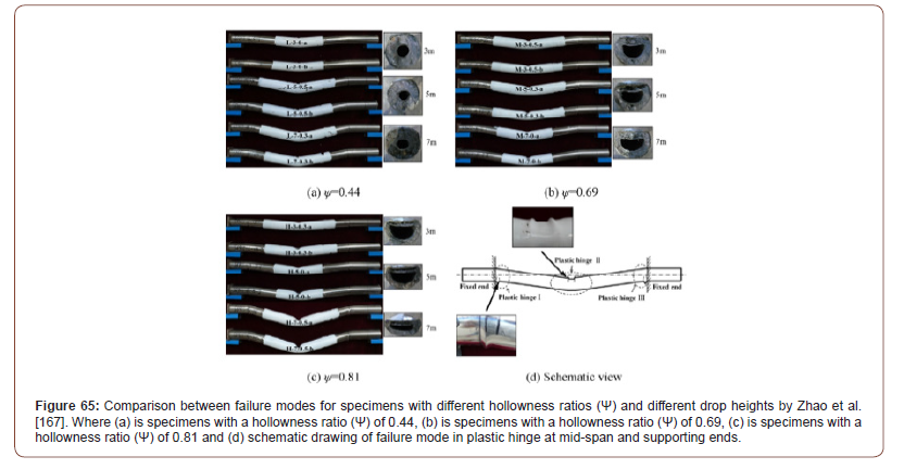

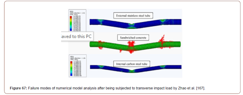
Wang et al. [146] has presented general deformation mode of failure at the mid-span for the tested CFST and CFDST specimens after impact. Moreover, the deformation failure mode at mid-span for specimen with tag numbers U-CFST-H2, U-CFST-H4, N-CFST-H4, U-CFDST-H4, N-CFDST-H4 has been presented experimentally and numerically in Figure 68 and Figure 69 respectively (Figures 68,69).
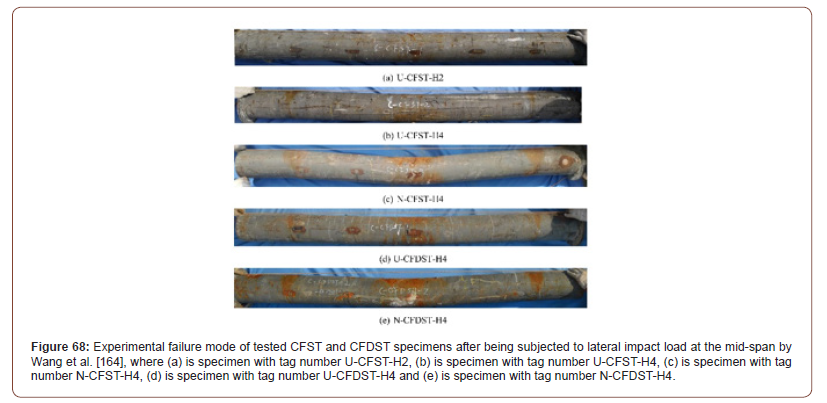
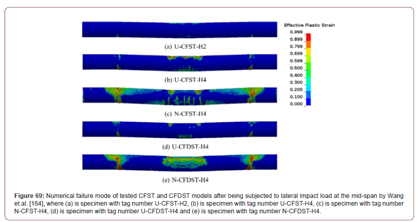
Yang et al. [168] has presented the typical failure modes in HSCFST experimental specimens for outer steel tube and inner concrete core fill after being subjected to transverse impact loading. Moreover, the typical steel failure mode was localized bugle (Figure 70). While the concrete core fill had typical cracks (1) at the support, (2) at top compression zone of the mid-span and (3) bottom tension zone of the mid-span (Figures 70,71).

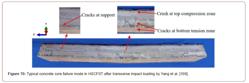
Impact force versus impact time
Generally speaking, there was a slight variation between the experimentally measured results and the numerically predicted results for impact force versus impact time for the tested specimens by Han et al. [110] However, specimens with tag numbers CC3, HCC and HCS had high differences between the experimentally measured results and the numerically predicted results for impact force versus impact time. Moreover, Specimens with tag numbers CC1, CC2, CC3, CS1, CS3 had impact time between 0.01 and 0.04 seconds. While specimens with tag numbers HCC, CS2, SS1, SS3 had impact time between 0.01 and 0.07 seconds. Additionally, specimen with tag number CS2 and HCS had impact time between 0.01 and 0.08 seconds. Besides, specimen with tag number HSS had the highest range of impact time and taking place between 0.01 and 0.12 seconds. Furthermore, Han et al. [110] has observed that the peak impact force occurs at the early beginning of the impact time for almost all the tested specimens. Nevertheless, the case was different for specimens with tag numbers HCC, HCS and HSS where the peak impact force took place at 0.05 seconds, 0.06 seconds and 0.02 seconds respectively. Also, the highest peak impact force was recorded at 800kN for specimens with tag numbers CC1, CC3 and SS3. Moreover, the highest peak impact force took place at 0.01 seconds impact time for all the three specimens (CC1, CC3 and SS3). On the contrary, specimen with tag number HSS had the lowest peak impact force with a value of 50kN and occurred at 0.02 seconds. Lastly, Figure 72 shows the experimentally measured and numerically predicted Impact force (kN) versus Impact Time (S) curves by Han et al. [110] (Figure 72).
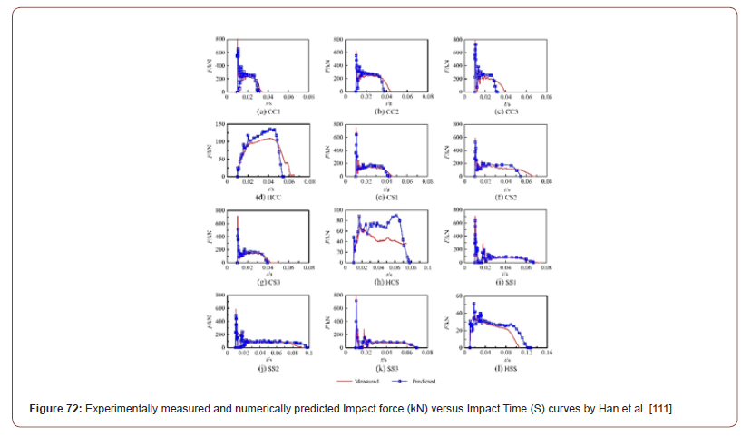
As shown in Figure 73, Yang et al. [158] has classified the general impact force (kN) versus impact time (S) curve into three stages. Moreover, the first stage is the oscillation stage (From Point O to Point A in Figure 73) which starts from the early stage (Point O in Figure 73) when the impact load contacts the CFST structural member up to the first third of the impact time (Point A in Figure 73). At this stage, the impact force behaves dynamically and usually, the peak impact force occurs at the oscillation stage. Afterwards, the second stage is the stabilization stage (From Point A to Point B in Figure 73) when the impact force starts to be steady in the magnitude (Point A in Figure 73) up to the second third of the impact time (Point B in Figure 73) where the impact force starts to decrease gradually. Then, the third final stage is the Attenuation stage (From Point B to Point C in Figure 73). At this stage, the impact force starts to reduce dramatically (Point B in Figure 73) up to the last third of the impact time (Point C in Figure 73) where the impact force stops completely effecting the CFST structural element (Figure 73).
Moreover, Figure 74 shows the comparison between the experimentally measured and numerically predicted Impact force (kN) versus Impact Time (S) curves for all the tested specimens by Yang et al. [158]. In addition, it was noticed that there is a high variation between the experimentally measured results and the numerically predicted results for impact force versus impact time for the tested specimens during the oscillation and stabilization stages. Furthermore, the impact force was monitored for all the specimens during the impact time between 0.00 and 0.048 seconds. Besides, Yang et al. [158] has observed that the peak impact force occurs at the early beginning of the impact time (0.01 seconds) for all the tested specimens. Also, the highest peak impact force was recorded at 900kN for specimens with tag numbers NC-0-6, NC- 0.15-6 and NC-0.3-6. Quite the reverse, specimen with tag number RAC1-0.16-2 had the lowest peak impact force with a value of 500kN and occurred at 0.01 seconds (Figure 74).
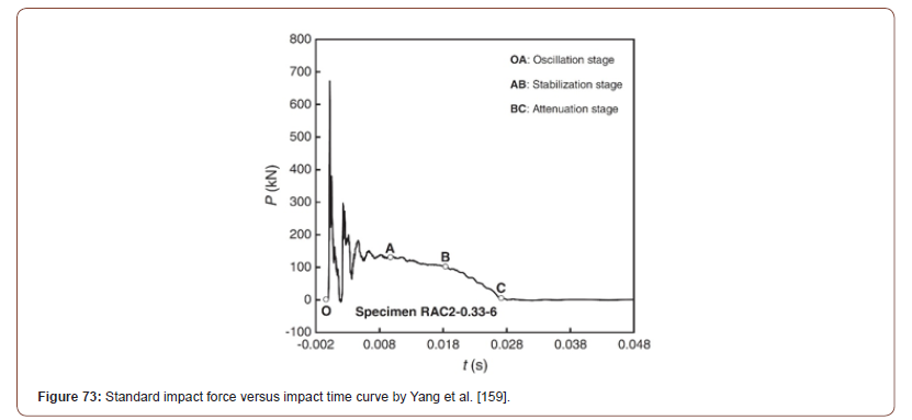
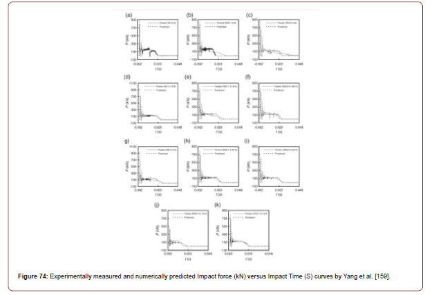
Wang et al. [162] has showed in Figure 75 the experimental Impact force (kN) versus Impact Time (S) curves for all the tested specimens. Furthermore, the impact force was monitored for all the specimens during the impact time as below:
1. Specimens with tag numbers RL01 and RL02 between 0.0 and 0.03 seconds.
2. Specimens with tag numbers RM01, RM02, F3L01, F2L01, F1L01 and F1L02 between 0.0 and 0.04 seconds.
3. Specimens with tag numbers RH01, RH02, F3M01, F3M02, F2M01, F2M02, F1M01 and F1M02 between 0.0 and 0.05 seconds.
4. Specimens with tag numbers F3H01, F3H 02, F2H01, F2H02 and F1H02 between 0.0 and 0.06 seconds.
Besides, Wang et al. [162] has observed that the peak impact force occurs at the early beginning of the impact time for all the tested specimens. Also, the highest peak impact force was recorded at approximate 290kN for specimen with tag numbers RH02. On the other hand, specimen with tag number F2L01 had the lowest peak impact force with a value of 100kN and occurred at approximately 0.0075 seconds (Figure 75).
Wang et al. [128] has presented the variance in behavior between impact force (kN) versus impact time (S) curves for different hollowness ratios (0.0, 0.3, 0.6, 0.7 and 0.8). As shown in Figure 76, as the hollowness ratio increases, (1) the impact force and the peak impact force decreases and (2) the impact time increases. Also, it could be assumed from the curves in Figure 76, that the low the hollowness ratio (Ψ), the more dynamic the impact force behavior with respect to impact time (Figure 76).
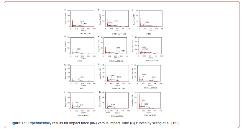
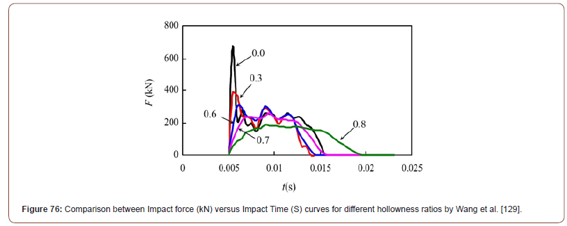
Alam et al. [171] has detected that the peak impact force occurs at the early beginning of the impact time (between 0.00 and 0.005 seconds) for all the tested specimens (Figure 77). Also, the highest peak impact force was recorded at 320kN for specimens with tag numbers GCFT-LL-V1 and GCCFT-LL-V1. Oppositely, specimens with tag numbers CFT-B-V2 and CCFT-LL-V2 had the lowest peak impact force with a value of 170kN (Figure 77).
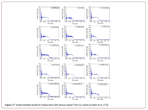
Hu et al. [175] had slight variation between the experimentally measured results and the numerically predicted results for impact force versus impact time for the tested specimens. But specimen with tag number CFP-2 had the largest variance between the experimentally measured results and the numerically predicted results for impact force versus impact time. Moreover, specimens with tag numbers CTP had impact time between 0.01 and 0.025 seconds. While specimens with tag numbers CFP-1, CTP-2 and CTN- 2 had impact time between 0.01 and 0.03 seconds. Additionally, specimen with tag number CFP-2, CFN-2, CTP-4 and CTN-4 had impact time between 0.01 and 0.04 seconds. Besides, specimens with tag numbers CFP-4 and CFN-4 had the highest range of impact time and taking place between 0.01 and 0.05 seconds. Furthermore, Hu et al. [175] has observed that the peak impact force occurs at the early beginning of the impact time (0.01 seconds) for all the tested specimens. Also, the highest peak impact force was recorded at 450kN for specimens with tag numbers CFP-4. Moreover, the highest peak impact force took place at 0.01 seconds. On the contrary, specimen with tag number CFP-1 had the lowest peak impact force with a value of 150kN and occurred at 0.01 seconds. Lastly, Figure 78 shows the experimentally measured and numerically predicted Impact force (kN) versus Impact Time (S) curves by Hu et al. [175] (Figure 78).
Zhao al. [166] has presented graphical comparisons between the experimentally measured and numerically predicted Impact force (kN) versus Impact Time (S) curves for all CFDST specimens as shown in Figure 79. Firstly, curve (a) L-3-0 in Figure 79 illustrates that life cycle of impact force took place between 0.005 and 0.025 seconds for specimen with tag number L-3-0-b. Additionally, the peak impact was recorded at impact time 0.005 seconds with a magnitude of 315kN. Furthermore, the impact force behaved dynamically starting from the initial stage reaching the peak and then dropped sharply to 0kN at approximately 0.0075 seconds. Then again increased suddenly from 0kN up to approximately 160kN at about 0.008 seconds. Afterwards, the impact force started to reach in a steady wavy manner (increasing and decreasing) starting from impact time 0.008 seconds until 0.02 seconds. Also, the impact force was traced to be about 110kN at impact time 0.02 seconds. From 0.02 seconds until 0.025 seconds, the impact force started to reduce dramatically until reaching 0kN and stops completely at 0.025 seconds. Besides, there was a good agreement between experimental and numerical results. Secondly, curve (b) L-5-0.5 in Figure 79 illustrates that life cycle of impact force took place between 0.005 and 0.035 seconds for specimens with tag numbers L-5-0.5-a and L-5-0.5-b. Additionally, the peak impact was recorded at impact time 0.006 seconds with a magnitude of 450kN. Furthermore, the impact force behaved dynamically starting from the initial stage reaching the peak and then dropped sharply to 10kN at approximately 0.008 seconds. Then again increased suddenly from 10kN up to approximately 150kN at about 0.0085 seconds. Afterwards, the impact force drops again to 90kN at 0.009 seconds. Then again for the third time, the impact force drops from 90kN to 60kN during the periods from 0.009 and 0.03 seconds respectively. Also, the fourth and the final drop in the magnitude of impact force was recorded between the periods 0.03 seconds (60kN) and 0.035 seconds (0kN). Thirdly, curve (c) L-7-0.3 in Figure 79 illustrates that life cycle of impact force took place between 0.005 and 0.034 seconds for specimen with tag number L-7-0.3-b. Additionally, the peak impact was recorded at impact time 0.006 seconds with a magnitude of 300kN. Furthermore, the impact force behaved dynamically starting from the initial stage reaching the peak and then dropped sharply to 0kN at approximately 0.007 seconds. Then again increased suddenly from 0kN up to approximately 170kN at about 0.008 seconds. Afterwards, the impact force reduces steadily until reaching 0kN and stops completely effecting the CFDST structural member at 0.034 seconds.
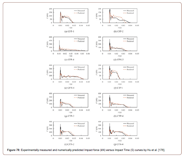
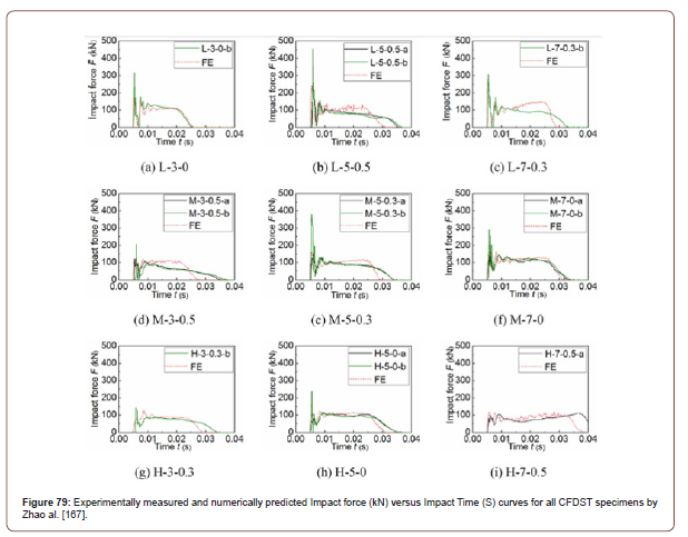
1. Fourthly, curve (d) M-3-0.5 in Figure 79 illustrates that life cycle of impact force took place as follows:
2. Specimen with tag number M-3-0.5-a between 0.005 and 0.035 seconds.
3. Specimen with tag number M-3-0.5-b between 0.005 and 0.0375 seconds.
4. Numerical model with tag number M-3-0.5 between 0.005 and 0.0275 seconds.
5. Additionally, the peak impact force was recorded at impact time as below:
6. The magnitude of the peak impact force was 120kN and recorded at 0.007 seconds for specimen with tag number M-3- 0.5-a.
7. The magnitude of the peak impact force was 200kN and recorded at 0.007 seconds for specimen with tag number M-3- 0.5-b.
8. The magnitude of the peak impact force was 120kN and recorded at 0.008 seconds for Numerical model with tag number M-3-0.5.
Furthermore, there is a high agreement and a good relation in impact force (kN) versus impact time (S) curves results for specimens with tag numbers M-3-0.5-a and M-3-0.5-b. Apart from the differences in the magnitude of the peak impact force. On the other hand, the Finite Element numerical model had a totally different behavior of the impact force during the impact time between 0.01 and 0.022 seconds. During this impact time (from 0.01 to 0.022 seconds) the magnitude of the impact force was higher than the results obtained for the experimental specimens with tag numbers M-3-0.5-a and M-3-0.5-b. Fifthly, curve (e) M-5-0.3 in Figure 79 illustrates that life cycle of impact force took place between (0.005 and 0.034 seconds) for specimens with tag numbers M-5-0.3-a and M-5-0.3-b. While the numerical model with tag number M-5-0.3 had impact force life cycle between (0.005 and 0.029 seconds). Additionally, the peak impact force for specimen with tag number M-5-0.3-a was recorded at impact time 0.006 seconds with a magnitude of 145kN. While the peak impact force for specimen with tag number M-5-0.3-b and numerical model with tag number M-5-0.3 was recorded at impact time 0.0055 seconds with a magnitude of 380kN and 150kN respectively. Sixthly, curve (f) M-7-0 in Figure 79 illustrates that life cycle of impact force took place between (0.005 to 0.0325 seconds), (0.005 to 0.034 seconds) and (0.005 to 0.031 seconds) for specimens with tag numbers M-7- 0-a, M-7-0-b and numerical model M-7-0 respectively. Besides, the peak impact force for specimens with tag numbers M-7-0-a, M-7- 0-b was recorded at impact time 0.006 seconds with a magnitude of 175kN and 290kN respectively. While the peak impact force for numerical model with tag number M-7-0 was recorded at impact time 0.008 seconds with a magnitude of 170kN. Seventhly, curve (g) H-3-0.3 in Figure 79 illustrates that life cycle of impact force took place between (0.006 to 0.034 seconds) for experimental specimen with tag number H-3-0.3-b. However, the numerical model with tag number H-3-0.3 had an impact force life cycle between 0.005 and 0.028 seconds. Moreover, the peak impact force for specimen with tag number H-3-0.3-b was recorded at impact time 0.006 seconds with a magnitude of 150kN. While the peak impact force for numerical model with tag number H-3-0.3 was recorded at impact time 0.009 seconds with a magnitude of 140kN. Eighthly, curve (h) H-5-0 in Figure 79 illustrates that life cycle of impact force took place between 0.005 and 0.035 seconds for specimens with tag numbers H-5-0-a and H-5-0-b. While the numerical model with tag number H-5-0 had impact force life cycle between 0.005 and 0.031 seconds. Besides, the peak impact force for specimens with tag numbers H-5-0-a and H-5-0-b was recorded at impact times 0.009 seconds and 0.0055 seconds, respectively. Additionally, the magnitudes of peak impact force for specimens with tag numbers H-5-0-a and H-5-0-b were 100kN and 240kN respectively. While, the peak impact force for the numerical model with tag number H-5-0 was recorded at impact time 0.008 seconds with a magnitude of 110kN. Ninthly, curve (i) H-7-0.5 in Figure 79 illustrates that life cycle of impact force took place between (0.005 to 0.04 seconds) for experimental specimen with tag number H-7-0.5-a. However, the numerical model with tag number H-7-0.5 had an impact force life cycle between 0.005 and 0.0375 seconds. Moreover, the peak impact force for specimen with tag number H-7-0.5-a was recorded at the impact times 0.009 and 0.0375 seconds with a magnitude of 100kN. While the peak impact force for numerical model with tag number H-7-0.5 was recorded at the impact times 0.006, 0.008 and 0.029 seconds with a magnitude of 110kN (Figure 79).
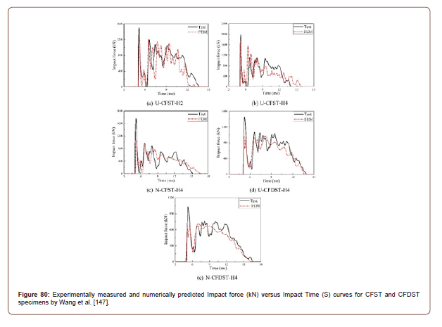
Wang et al. [163] has found slight variation between the experimentally measured results and the numerically predicted results for impact force versus impact time for the tested CFST and CFDST specimens. However, specimens with tag numbers N-CFST-H4, U-CFDST-H4 and N-CFDST-H4 had high differences between the experimentally measured results and the numerically predicted results for impact force versus impact time. All the tested specimens had dynamic wavy curve behavior for the impact force during its life period. Moreover, the impact time frame in milliseconds for the tested specimens were as below:
1. Specimen with tag number U-CFST-H2 had an impact time frame between 5 and 13.5 (ms).
2. Specimen with tag number U-CFST-H4 had an impact time frame between 5 and 16 (ms).
3. Specimen with tag number N-CFST-H4 had an impact time frame between 5 and 16.5 (ms).
4. Specimen with tag number U-CFDST-H4 had an impact time frame between 5 and 14 (ms).
5. Specimen with tag number N-CFDST-H4 had an impact time frame between 5 and 16.5 (ms).
Furthermore, Wang et al. [163] has observed that the peak impact force occurs at the early beginning of the impact time for all the tested CFST and CFDST specimens. Also, the highest peak impact force was recorded at 2000kN for specimen with tag numbers U-CFST-H4 and took place at an impact time of 5 milliseconds approximately. On the contrary, specimen with tag number N-CFDST-H4 had the lowest peak impact force with a value of 1050kN and occurred at an impact time of 5 milliseconds approximately. Lastly, Figure 80 shows experimentally measured and numerically predicted Impact force (kN) versus Impact Time (ms) curves for CFST and CFDST specimens by Wang et al. [163] (Figure 80).
Mid-span deflection versus impact time and residual displacement
Yousuf et al. [106] has presented in Figure 81 the mid-span deflection versus impact time curve for experimental specimen and numerical model results. As can be seen, for the experimental specimen results, the deflection in mid-span increases sharply from 0 to 0.04 seconds. Furthermore, the maximum deflection in the mid-span is reached at approximately 0.04 seconds with a magnitude of 70mm approximately. Then the deflection starts to reduce sharply with almost the same level as the initial increase until reaching approximately 30mm. Afterwards, the deflection starts to behave dynamically in a continuous steady wavy manner. Similarly, for the numerical model results, the deflection in midspan increases sharply from 0 to 0.05 seconds. Furthermore, the maximum deflection in the mid-span is reached at approximately 0.05 seconds with a magnitude of 78mm approximately. Then the deflection starts to reduce sharply with almost the same level as the initial increase until reaching approximately 20mm. However, the deflection after this point starts to increase and decrease slowly until becoming steady until the end of the time frame of the impact (Figure 81).
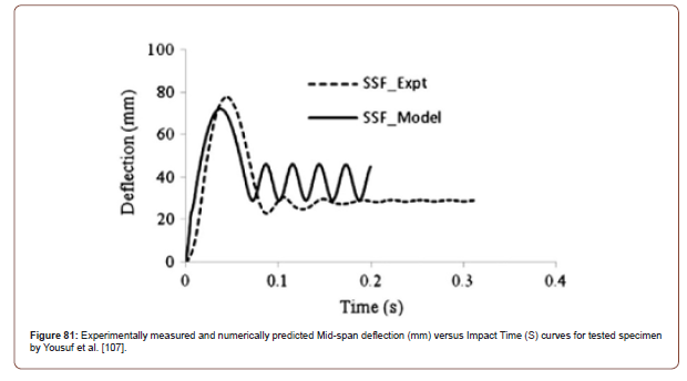
Han et al. [157] has presented the experimentally measured and numerically predicted Mid-span deflection (mm) versus Impact Time (S) curves for tested CFST specimens. As shown in Figure 81, the deflection in the mid-span increases steadily as the impact time increases. In addition, it has been determined that once the maximum mid-span deflection is reached it will stay constant at this point until the end of the impact time. Moreover, the maximum mid-span deflection among all specimens was recorded for the specimen with tag number SS3 with a value of 167mm for experimental specimen results and 174mm for the numerical model results. Figure 82 displays experimentally measured and numerically predicted Mid-span deflection (mm) versus Impact Time (S) curves for tested specimens by Han et al. [157], where (a) is specimen with tag number CC1, (b) is specimen with tag number CC2, (c) is specimen with tag number CS2, (d) is specimen with tag number CS3, (e) is specimen with tag number SS1, (f) is specimen with tag number SS2, (g) is specimen with tag number SS3, (h) is specimen with tag number HSS (Figure 82).
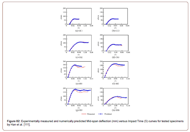
Yang et al. [158] has showed the experimentally measured and numerically predicted Mid-span deflection (mm) versus Impact Time (S) curves for tested RACFST specimens. As shown in Figure 83, the deflection in the mid-span increases steadily as the impact time increases. In addition, it has been determined that once the maximum mid-span deflection is reached it will stay constant at this point until the end of the impact time for specimen with tag number NC-0.3-6. However, the case was different for specimens with tag numbers NC-0-6, RAC1-0-6, RAC2-0-6, NC-0.15-6, RAC1- 0.16-6, RAC2-0.165-6, RAC1-0.32-6, RAC2-0.33-6, RAC1-0.16-2 and RAC1-0.16-4 where the mid-span deflection started to decrease noticeably after reaching the maximum. Moreover, the maximum mid-span deflection among all specimens was recorded for the specimen with tag number NC-0.3-6 with a value of 100.7mm for experimental specimen results. Figure 83 shows experimentally measured and numerically predicted Mid-span deflection (mm) versus Impact Time (S) curves for tested specimens by Yang et al. [158], where (a) is specimen with tag number NC-0-6, (b) is specimen with tag number RAC1-0-6, (c) is specimen with tag number RAC2-0-6, (d) is specimen with tag number NC-0.15-6, (e) is specimen with tag number RAC1-0.16-6, (f) is specimen with tag number RAC2-0.165-6, (g) is specimen with tag number NC-0.3-6, (h) is specimen with tag number RAC1-0.32-6, (i) is specimen with tag number RAC2-0.33-6, (j) is specimen with tag number RAC1- 0.16-2 and (k) is specimen with tag number RAC1-0.16-4 (Figure 83).
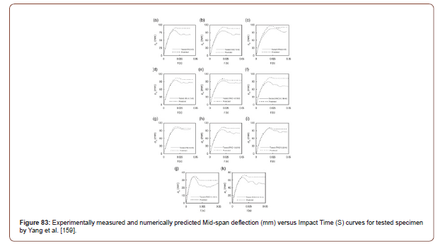
Wang et al. [126] has showed the experimentally measured Mid-span deflection (mm) versus Impact Time (S) curves for tested FRP–concrete–steel double skin tubular specimens. As shown in Figure 84, the deflection in the mid-span increases steadily as the impact time increases. In addition, it has been determined that once the maximum mid-span deflection is reached, it will start to decrease noticeably after reaching the maximum. After the decrease of mid-span deflection with respect to time, the residual deflection is reached and stabilized until the end of the impact load. Moreover, the maximum mid-span deflection among all specimens was recorded for the specimen with tag number RH01 bared/ unstrengthen specimen with a value of 278.6mm for experimental specimen results. Additionally, specimen with tag number F1H01 with 1 FRP layer had the highest residual deflection with a magnitude of 99.8mm. On the contrary, specimen with tag number F3L01 with 3 FRP layers had the lowest mid-span deflection value of 78.8mm. While the lowest residual displacement was recorded at 17.6mm for the bared/unstrengthen specimen RL02. As such, it can be concluded that the higher the number of FRP strengthening layers on FRP–concrete–steel double skin tubular specimens, the lower the mid-span deflection when comparing the results with bared specimens. Furthermore, Figure 84 shows experimentally measured mid-span deflection (mm) versus Impact Time (S) curves for tested specimens by Wang et al. [126], where (a) are specimens with tag numbers F1L01 and F1L02, (b) specimens with tag numbers F1M01 and F1M02, (c) specimens with tag numbers F1H01 and F1H02, (d) specimens with tag numbers F2L01 and F2L02, (e) specimens with tag numbers F2M01 and F2M02, (f) specimens with tag numbers F2H01 and F2H02, (g) are specimens with tag numbers F3L01 and F3L02, (h) specimens with tag numbers F3M01 and F3M02, (i) specimens with tag numbers F3H01 and F3H02, (j) specimens with tag numbers RL01 and RL02, (k) specimens with tag numbers RM01 and RM02, (l) specimens with tag numbers RH01 and RH02 (Figure 84).
Alam et al. [171] has presented in Figure 85 the experimentally measured lateral displacement at mid-span (mm) versus impact time (S) curves for the tested specimens with tag numbers as below:
1. CFT-B-V1 (1) Bare specimen,
2. CCFT-LL-V1 with 2 layers – CFRP (1300mm bond length)
3. CFT-B-V2 Bare specimen
4. CCFT-LL-V2 – with 2 CFRP layers (1300mm bond length)
As can be seen in the curves in Figure 85, the maximum lateral displacement was recorded for the bare specimen with tag number CFT-B-V1 (1) with a magnitude of 87mm and a and a residual displacement with a value of 79.2mm. Moreover, the bare specimen with tag number CFT-B-V2 had a lateral displacement with a value of 40mm and a residual displacement with a value of 31mm. Furthermore, specimen with tag number CCFT-LL-V1 with 2 layers of CFRP and a bond length of 1300mm had lateral displacement and residual displacement with values of 76.5mm and 65.3mm respectively. In addition, specimen with tag number CCFT-LL-V2 with 2 layers of CFRP and a bond length of 1300mm had lateral displacement and residual displacement with values of 30.5mm and 20mm respectively. Accordingly, it can be concluded that the lateral and residual displacements reduce after impact loading when reinforcing CFST structural members with FRP (Figure 85).
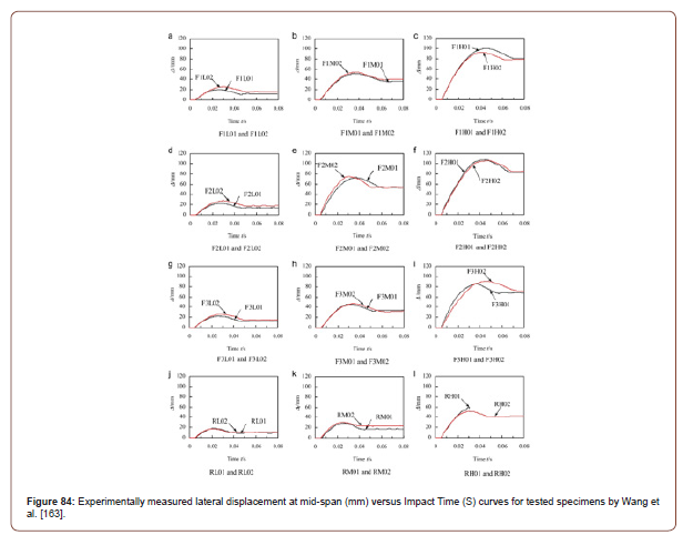
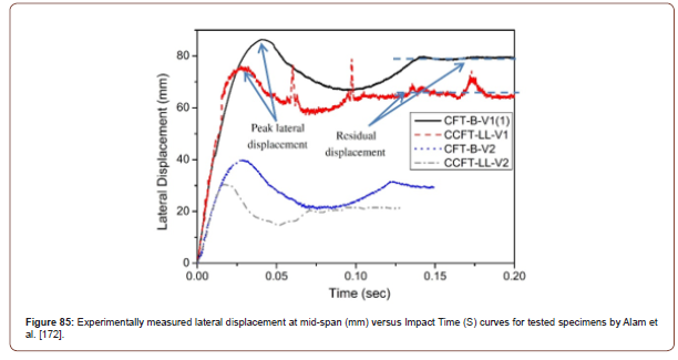
Hu et al. [175] has showed the experimentally measured and numerically predicted Mid-span deflection (mm) versus Impact Time (S) curves for tested CFST specimens. As shown in Figure 86, the deflection in the mid-span increases steadily as the impact time increases. In addition, it has been determined that once the maximum mid-span deflection is reached it will stay constant at this point until the end of the impact time for specimens with tag numbers CFP-2, CFP-3, CFN-2, CTP-2 and CTN-2. However, the case was different for specimens with tag numbers CFP-1 and CTP- 1, where the mid-span deflection started to decrease noticeably after reaching the maximum. Moreover, the maximum mid-span deflection among all specimens was recorded for the specimen with tag number CFP-3 with a value of 82mm for experimental specimen results and 73mm for the numerical model results. Figure 86 shows experimentally measured and numerically predicted Mid-span deflection (mm) versus Impact Time (S) curves for tested specimens by Hu et al. [175], where (a) is specimen with tag number CFP-1, (b) is specimen with tag number CFP-2, (c) is specimen with tag number CFP-3, (d) is specimen with tag number CFN-2, (e) is specimen with tag number CTP-1, (f) is specimen with tag number CTP-2, (g) is specimen with tag number CTN-2 (Figure 86).
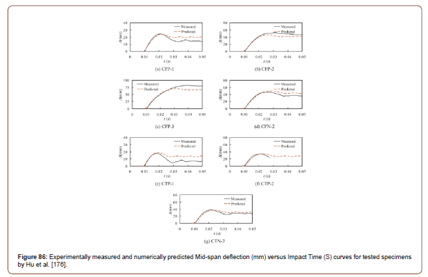
Zhao et al. [166] has showed the experimentally measured and the numerically predicted Mid-span deflection (mm) versus Impact Time (S) curves for tested CFDST specimens. As shown in Figure 87, the deflection in the mid-span increases steadily as the impact time increases. Afterwards, the mid-span deflection stabilizes with respect to time until the end of the impact load which represents the residual deflection. Moreover, the maximum mid-span deflection among all specimens was recorded for the specimen with tag number H-7-0.5-a with a value of 161.4mm for experimental specimen results and 148.8mm for the numerical model results. Additionally, specimen with tag number H-7-0.5-b had the highest residual deflection with a magnitude of 161.1mm. On the contrary, specimen with tag number L-3-0-b had the lowest mid-span deflection value of 50.5mm. While the lowest residual displacement was recorded at 39.5mm for the specimen L-3-0-a. Furthermore, Figure 87 shows experimentally measured and numerically predicted mid-span deflection (mm) versus Impact Time (S) curves for tested specimens by Zhao et al. (2019), where (a) is specimen with tag number L-3-0, (b) are specimens with tag numbers L-5- 0.5-a and L-5-0.5-b, (c) are specimens with tag numbers M-3-0.5-a and M-3-0.5-b, (d) are specimens with tag numbers M-5-0.3-a and M-5-0.3-b, (e) are specimens with tag numbers M-7-0-a and M-7- 0-b, (f) is specimen with tag number H-3-0.3-b, (g) are specimens with tag numbers H-5-0-a and H-5-0-b, (h) is specimen with tag number H-7-0.5-a (Figure 87).
Wang et al. [146] has presented in Figure 88 the mid-span deflection versus impact time curve for experimental specimen and finite element numerical model results. As can be seen, the deflection in mid-span increases sharply until it reaches the maximum deflection and starts to reduce sharply with almost the same level as the initial increase. Afterwards, the deflection starts to behave dynamically in a continuous steady wavy manner. Similar mid-span behavior with respect to impact time was observed for the finite element numerical model results. Moreover, the maximum mid-span deflection among all specimens was recorded for the specimen with tag number N-CFST-H4 with Normal Strength Concrete (NSC) with a value of 35.3mm for experimental specimen results. Additionally, the same specimen N-CFST-H4 had the highest residual deflection with a magnitude of 23mm. On the contrary, specimen with tag number U-CFST-H2 with Ultra-High-Performance Fiber Reinforced Concrete (UHPFRC) fill had the lowest mid-span deflection value of 17.5mm. While the lowest residual displacement was recorded at 8.4mm for the same specimen U-CFST-H2. According, it has been found that CFST filled with Ultra-High-Performance Fiber Reinforced Concrete (UHPFRC) had lower mid-span deflection and lower residual displacement when compared with CFST filled with Normal Strength Concrete (NSC). Furthermore, Figure 88 shows a comparison between experimentally measured and numerically predicted lateral displacement at mid-span (mm) versus Impact Time (S) curves for tested specimens by Wang et al. (2019), where (a1) is specimen with tag number U-CFST-H2:LVDT-1, (a2) is specimen with tag number U-CFST-H2:LVDT-2, (a3) is specimen with tag number U-CFST-H2:LVDT-3, (b1) is specimen with tag number U-CFST-H4:LVDT-1, (b2) is specimen with tag number U-CFST-H4:LVDT-2, (b3) is specimen with tag number U-CFSTH4: LVDT-3, (c1) is specimen with tag number N-CFST-H4:LVDT-1, (c2) is specimen with tag number N-CFST-H4:LVDT-2, (c3) is specimen with tag number N-CFST-H4:LVDT-3, (d1) is specimen with tag number U-CFDST-H4:LVDT-1, (d2) is specimen with tag number U-CFDST-H4:LVDT-2, (d3) is specimen with tag number U-CFDST-H4:LVDT-3, (e1) is specimen with tag number N-CFSTH4: LVDT-1, (e2) is specimen with tag number N-CFST-H4:LVDT-2, (e3) is specimen with tag number N-CFST-H4:LVDT-3 (Figure 88).
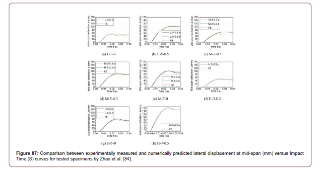
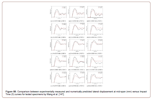
Yang et al. [170] has showed the experimentally measured and numerically predicted Mid-span deflection (mm) versus Impact Time (S) curves for tested HSCFST specimens. As shown in Figure 89, the deflection in the mid-span increases steadily as the impact time increases. In addition, it has been determined that once the maximum mid-span deflection is reached, it will start to decrease noticeably after reaching the maximum. Moreover, the maximum mid-span deflection among all specimens was recorded for the specimen with tag number NS7-100-4 (impact energy Ei=37.3kJ) with a value of 84.6mm for experimental specimen results and 82mm for the numerical model. Figure 89 shows experimentally measured and numerically predicted Mid-span deflection (mm) versus Impact Time (S) curves for tested specimens by Yang et al. [170], where (a) is specimen with tag number HS-100-6, (b) is specimens with tag number HS-60-6, (c) is specimen with tag number NS-100-6, (d) is specimen with tag number NS-60-6, (e) is specimen with tag number NS-100-5 and (f) is specimen with tag number NS-100-4. Furthermore, each specimen had three repetitions, where each repetition represents different impact energy. Besides, the impact energies (Ei) which were evaluated were 37.3kJ, 29.1kJ and 12.5kJ. Additionally, it was found that as the impact energy increases, the mid-span deflection increases (Figure 89).
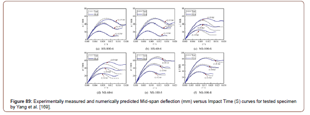
Conclusion
The conclusion has been divided into two sections. Where the first part discusses the summary of the review and the second sections provides suggestions and recommendations given by the author to enhance the structural performance of CFST columns subjected to impact loading.
Summary
Han et al. [157] had the highest drop height and the highest drop mass weight among all other researchers with values of 8m and 920kg respectively. On the other hand, Yang et al. [168] had the highest impact energy among all other researchers with magnitude of 37.3kJ. Even though Wang et al. [127] did not specify the tested impact drop height, the tested specimen number RH01 (Bared Specimen) had the highest maximum deflection among all other researchers with a value of 278.6mm. Although, Wang et al. [127] had the highest maximum deflection among all other researchers, the highest impact time and the highest residual displacement after impact load was recorded by Zhao et al. [166] for specimen with tag number H-7-0.5-b (Figure 97) with magnitudes of 62.7 milliseconds and 161.1mm respectively. Conversely, Wang et al. [127] had the highest impact force plateau among all other researchers with a rate of 812kN. Moreover, Figure 90 shows a graphical illustration of the comparison made between the lengths of the maximum drop height of the impact load by researchers (Figure 90).
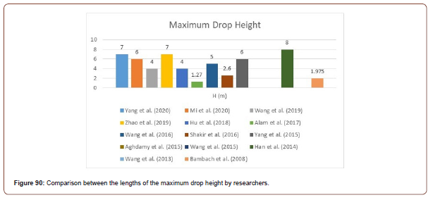
Besides, Figure 91 shows a graphical illustration of the comparison made between the maximum mass weights of the indenters of the impact load by researchers (Figure 91).
Furthermore, Figure 92 shows a graphical illustration of the comparison made between the maximum impact energies of the indenters of the impact load by researchers (Figure 92).
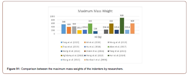
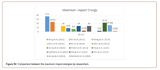
Furthermore, Figure 93 shows a graphical illustration of the comparison made between the maximum displacements after impact load by researchers (Figure 93).
Furthermore, Figure 94 shows a graphical illustration of the comparison made between the maximum impact times in milliseconds by researchers (Figure 94).
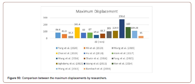
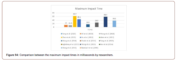
Furthermore, Figure 95 shows a graphical illustration of the comparison made between the maximum impact force plateaus by researchers (Figure 95).
Furthermore, Figure 96 shows a graphical illustration of the comparison made between the maximum residual displacements after impact load by researchers [187-193] (Figures 96,97).
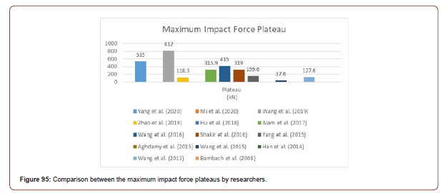
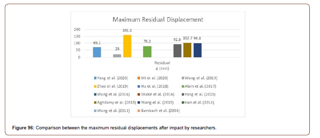

To complete the comparison between the previous researchers and to determine which study needs further investigations for improvement, the author showed a comparison between the lowest effected specimens after impact by researchers (Table 4). Although, Aghdamy et al. [159] had the highest lowest maximum displacement and the highest lowest residual displacement with magnitudes of 87.2mm and 56.9mm, other important results were not recorded by Aghdamy et al. [159]. Such as drop height, impact energy, impact time and impact force plateau. However, specimen number L-3-0-a by Zhao et al. [166] had the second highest lowest residual displacement and the third highest lowest maximum displacement with values of 39.5mm and 50.5mm respectively. Those magnitudes obtained by Zhao et al. [166] are considered high when considering that specimen number L-3-0-a had the third highest lowest drop height, the third lowest impact mass, the third highest lowest impact energy, the second highest lowest impact time and one of the lowest impact force plateau magnitudes. The author of this literature review paper believes that the low performance against impact for the tested specimens by Zhao et al. [166] could be due to several factors such as below:
1. The small sized cross-sectional dimensions of the tested specimens.
2. Using Normal Strength Concrete (NSC) sandwich fill between the outer stainless-steel tube and the inner carbon steel tube.
3. Keeping the inner carbon steel tube hollow without concrete fill.
4. Did not reinforce the CFDST specimens with FRP material (Table 4).
Table 23:Comparison between the lowest effected specimens after impact by researchers.
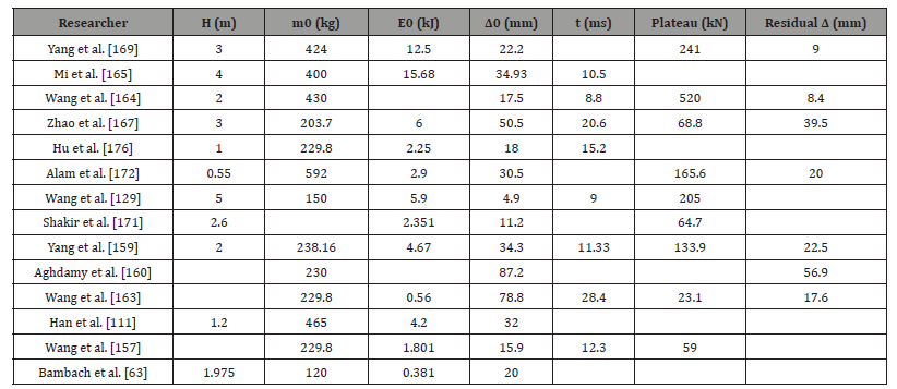
Findings and recommendations
Finally, and based on analyzing the previous investigations, the major findings by past researchers to increase the impact resistivity and to reduce damage of concrete filled steel tubes after impact loading has been presented below:
1. Bambach [86] concluded that stainless steel tubes perform better and has higher impact load bearing capacity than the classical normal steel. Besides, the impact absorption rate of stainless steel is 1.8 times higher than normal mild steel. This has been clarified due to the higher characteristics and material properties, such as strain failure.
2. Bukovská & Karmazínová [149] concluded that the tensile and shear strength increases under compression when using high strength concrete fill in CFST columns.
3. Evirgen et al. [150] observed that the circular geometrical CFST section is the most suitable section in terms of ductility and resistivity against axial stress.
4. Yousuf et al. [118] has found that using stainless steel tubes increases the global impact resistance of CFST columns and reduces buckling. In addition, CFST columns had lower maximum deflection under impact load when compared to hollow tubes.
5. Wang et al. [127] found that as the number of outer FRP layers increases, the impact resistance of FRP-Concrete-Steel double skin tubular member’s increases.
6. Wang et al. [127] found that Fixed-fixed boundary condition support has lower local deformation under lateral impact than rotational restraint boundary condition supported specimens.
7. Alam et al. [171] Strengthening CFST members with GFRP performs better than CFRP under lateral impact load.
8. Wang et al. [163] UHPFRC filled steel tube has greater lateral impact resistance, greater peak, lower local indentation, and fewer deflection than NSC filled steel tubes.
9. Mi et al. [164] observed that (1) By using Ultra-High- Performance Fiber-Reinforced Concrete (UHPFRC) the bearing capacity of non-impacted samples increases by 47.1% when compared with specimens filled with Normal-Strength Concrete (NSC) and (2) Using Ultra-High-Performance Fiber-Reinforced Concrete (UHPFRC) fill in CFST columns improves the residual performance significantly.
10. Xian et al. [178], the results showed that the fixed-fixed boundary conditions for SRCFST have the highest impact resistance performance and reduces the mid-span deflection.
Accordingly, the author of this literature review manuscript believes, that further investigations should be carried out in this domain to enhance the global structural performance of CFST after being subjected to transverse impact loads. For example, even though the previous studies have analyzed double skinned steel tubes filled with concrete under impact loads, the past research has never studied the impact behavior of triple skinned steel tubes filled with concrete subjected to transverse impact loads. As such the author of this review paper strongly believes that by applying a third skin steel tube on the CFDST specimens which was carried out by Zhao et al. [166], the impact resistivity will increase (due to the fact that a third skin steel tube will add a second concrete fill sandwich layer). As such, the author proposes a novel design of a circular hybrid triple skin stainless steel tubular column filled with UHPFRC and externally strengthened with GFRP subjected to transverse impact load.
Acknowledgment
None.
Conflict of Interest
No conflict of interest.
References
- Abaqus (2007) ABAQUS Standard User's Manual, Version 6.7. Providence, RI, Dassault Systèmes Corp, USA.
- Thomas SG, Reid SR, Johnson W (1976) Large deformations of thin-walled circular tubes under transverse loading-I: An experimental survey of the bending of simply supported tubes under a central load. International Journal of Mechanical Sciences 18(6): 325-326.
- Watson AR, Reid SR, Johnson W (1976) Large deformations of thin-walled circular tubes under transverse loading-III: Further experiments on the bending of simply supported tubes. International Journal of Mechanical Sciences 18(9-10): 501-502.
- Watson AR, Reid SR, Johnson W, Thomas SG (1976) Large deformations of thin-walled circular tubes under transverse loading - II: Experimental study of the crushing of circular tubes by centrally applied opposed wedge-shaped indenters. International Journal of Mechanical Sciences 18(7-8): 387-397.
- Goode C D, Fatheldin YT (1980) Sandwich cylinders (steel-concrete-steel) subjected to external pressure. ACI J 77(2): 109-115.
- De Oliveira J, Wierzbicki T, Abramowicz W (1982) Plastic behaviour of tubular members under lateral concentrated loading, Nor. Veritas Tech. Rep. 82-0708.
- Soreide TH, Amdahl J (1982) Deformation’s characteristics of tubular members with reference to impact loads from collisions and dropped objects. Norw Marit Res 10: 3-12.
- Abramowicz W, Jones N (1984) Dynamic axial crushing of square tubes. International Journal of Impact Engineering 2: 179-208.
- Xiaoqing M, Stronge WJ (1985) Spherical missile impact and perforation of filled steel tubes. International Journal of Impact Engineering 3(1): 1-16.
- Bischoff PH, Perry SH (1991) Compressive behaviour of concrete at high strain rates. Materials and Structures 24 (6): 425-450.
- Tomii M (1991) Ductile and strong columns composed of steel tube, in-filled concrete, and longitudinal steel bars. Special volume. Proceedings of the third international conference on steel-concrete composite structures, Japan, pp. 39-66.
- Bergmann R (1994) Load introduction in composite columns filled with high strength concrete. Proceedings of the 6th international symposium on tubular structures pp: 373-380.
- Lu YQ, Kennedy DJL (1994) The flexural behaviour of concrete-filled hollow structural sections. Canadian Journal of Civil Engineering 21(1): 111-130.
- Bergmann R, Matsui C, Meinsma C, Dutta D (1995) CIDECT design guide for concrete filled hollow section columns under static and seismic loading. Verlag, TUV Rheinland.
- Mays GC, Smith PD (1995) Blast effects on buildings. London: Thomson Telford.
- Wei S, Mau ST, Vipulanandan C (1995) Performance of new sandwich tube under axial loading: experiment. Journal of Structural Engineering 121(12): 1806-1814.
- Jones N, Birch RS (1996) Influence of internal pressure on the impact behavior of steel pipelines. Trans ASME J Press Vessel Technol 118: 464-471.
- (1997) ASCCS, Concrete Filled Steel Tubes Seminar by, Association for International Cooperation and Research in Steel-concrete Composite Structures.
- (1997) Association for International Cooperation and Research in Steel-Composite Structures. Concrete filled steel tubes a comparison of international codes and practices. Innsbruck: ASCCS Seminar Report.
- Jones N (1997) Structural Impact. (2nd), Cambridge, Cambridge University Press, UK.
- Shen WQ, Chen KS (1998) An investigation on the impact performance of pipelines. International Journal of Crashworthiness. 3(2): 191-209.
- Burgan BA, Baddoo NR, Gilsenan KA (2000) Structural design of stainless-steel members comparison between Eurocode 3, Part 1.4 and test results. Journal of Constructional Steel Research 54 (1): 51-73.
- Hajjar J (2000) Concrete-filled steel tube columns under earthquake loads. Progress in Structural Engineering and Materials 2(1): 72-81.
- Rasmussen KJR (2000) Recent research on stainless steel tubular structures. Journal of Constructional Steel Research 54(1): 75-88.
- Elchalakani M, Zhao XL, Grzebieta RH (2001) Concrete-filled circular steel tubes subjected to pure bending. Journal of Constructional Steel Research 57(11): 1141-1168.
- Morino S, Uchikoshi M, Yamaguchi I (2001) Concrete-filled steel tube column system its advantages. International Journal of Steel Structures 1(1): 33-44.
- Rasmussen KJR (2001) Full-range stress–strain curves for stainless steel alloys. Research Report No R811. Centre for Advanced Structural Engineering, The University of Sydney, Australia.
- Shanmuam NE, Lakshmi B (2001) State of the art report on steel-concrete composite columns. Journal of Constructional Steel Research 57(10): 1041-1080.
- Elchalakani M, Zhao XL, Grzebieta RH (2002) Tests on concrete filled double-skin (CHS outer and SHS inner) composite short columns under axial compression. Thin-Walled Structures 40 (5): 415-441.
- Elremaily A, Azizinamini A (2002) Behavior and strength of circular concrete-filled tube columns. Journal of Constructional Steel Research 58(12): 1567-1591.
- Morino S, Tsuda K (2002) Design and construction of concrete-filled steel tube column system in Japan. Earthq Eng Eng Seismol 4(1): 51-73.
- Zeinoddini M, Parke GAR, Harding JE (2002) Axially pre-loaded steel tubes subjected to lateral impacts: an experimental study. International Journal of Impact Engineering 27(6): 669-690.
- Elchalakani M (2003) Cyclic bending behaviour of hollow and concrete-filled cold formed circular steel members. Ph.D. thesis. Monash University, Australia.
- Hu HT, Huang CS, Wu MH, Wu YM (2003) Nonlinear analysis of axially loaded concrete filled tube columns with confinement effect. Journal of Structural Engineering ASCE 129(10): 1322-1329.
- Liu D, Gho W, Yuan J (2003) Ultimate capacity of high-strength rectangular concrete-filled steel hollow section stub columns. Journal of Constructional Steel Research 59(12): 1499-1515.
- Mursi M, Uy B (2003) Strength of concrete filled steel box columns incorporating interaction buckling. Journal of Structural Engineering ASCE 129(5): 626-639.
- Nethercot DA (2003) Composite construction. London: Spon Press, UK.
- European Committee for Standardization (2004) EN1994-1-1, Eurocode: Design of composite steel and concrete structures-Part 1.1-General rules and rules for buildings. EN 1994-1-1:2004: E. European Committee for Standardization, London.
- Fam A, Qie FS, Rizkalla S (2004) Concrete-filled steel tubes subjected to axial compression and lateral cyclic loads. Journal of Structural Engineering 130(4): 631-640.
- Gho WM, Liu D (2004) Flexural behaviour of high-strength rectangular concrete-filled steel hollow sections. Journal of Constructional Steel Research 60(11): 1681-1696.
- Han LH (2004) Flexural behaviour of concrete-filled steel tubes. Journal of Constructional Steel Research 60(2): 313-337.
- Jiao H, Zhao XL (2004) CFRP strengthened butt-welded very high strength (VHS) circular steel tubes. Thin-Walled Structures 42: 963-978.
- Sakino K, Nakahara H, Morino S, Nishiyama I (2004) Behavior of centrally loaded concrete-filled steel-tube short columns. Journal of Structural Engineering 130(2): 180-188.
- Varma AH, Ricles JM, Sause R, Lu LW (2004) Seismic behavior and design of high-strength square concrete-filled steel tube beam columns. Journal of Structural Engineering 130(2): 169-179.
- (2005) EN 1991-1-7, Eurocode 1-actions on structures, part 1-7: general actions–accidental actions, Brussels: European Committee for Standardization.
- European Committee for Standardization (2005) EN1991-1-7, Eurocode 1-Actions on Structures. Part 1-7: General Actions-Accidental actions. Brussels.
- Gardner L (2005) The use of stainless steel in structures. Progress in Structural Engineering and Materials 7(2): 45-55.
- Han LH, Yang YF (2005) Cyclic performance of concrete-filled steel CHS columns under flexural loading. Journal of Constructional Steel Research 61(4): 423-452.
- Xiao Y, He W, Choi KK (2005) Confined concrete-filled tubular columns. Journal of Structural Engineering 131(3): 488-497.
- Ellobody E, Young B (2006) Design and behaviour of concrete-filled cold-formed stainless steel tube columns. Engineering Structures 28(5): 716-728.
- Young B, Ellobody E (2006) Experimental investigation of concrete-filled cold-formed high strength stainless steel tube columns. Journal of Constructional Steel Research 62(5): 484-492.
- Habel K, Viviani M, Denarié E, Brühwiler E (2006) Development of the mechanical properties of an ultra-high performance fiber reinforced concrete (UHPFRC). Cement and Concrete Research 36(7): 1362-1370.
- Han LH, Huang H, Tao Z, Zhao XL (2006) Concrete-filled double skin steel tubular (CFDST) beam-columns subjected to cyclic bending. Engineering Structures 28 (12): 1698-1714.
- Japan Society of Civil Engineers (2006) Recommendations for design and construction of ultra-high strength fiber reinforced concrete structures.
- Rasmussen K J R, Ranzi G (2006) Strength of concrete-filled stainless-steel tubes under impact loading. Progress in mechanics of structures and materials, New Zealand.
- Han LH, Yao G, Tao Z (2007) Performance of concrete-filled thin-walled steel tubes under pure torsion. Thin Wall Structures 45(1): 24-36.
- Kang JY, Choi ES, Chin WJ, Lee JW (2007) Flexural behavior of concrete-filled steel tube members and Its application. International Journal of Steel Structures 7: 319-324.
- Rasmussen KJR, Ranzi G (2007) Strength of concrete-filled stainless-steel tubes under impact loading. In: 19th Australasian Conference on the Mechanics of Structures and Materials Pp. 811-816.
- Shan JH, Chen R, Zhang WX, Xiao Y, Yi W J, et al. (2007) Behavior of concrete filled tubes and confined concrete filled tubes under high-speed impact. Advances in Structural Engineering 10(2): 209-218.
- Tao Z, Han LH, Wang LL (2007) Compressive and flexural behaviour of CFRP repaired concrete-filled steel tubes after exposure to fire. Journal of Constructional Steel Research 63(8): 1116-1126.
- Uy B, Remennikov A (2007) The behaviour of concrete filled steel columns subjected to transverse impact loads. Proceedings of the 5th International Conference on Advances in Steel Structures, Singapore, pp. 929-934.
- Baddoo NR (2008) Stainless steel in construction: a review of research, application, challenges and opportunities. Journal of Constructional Steel Research 64 (11): 1199-1206.
- Bambach MR, Jama H, Zhao XL, Grzebieta RH (2008) Hollow and concrete filled steel hollow sections under transverse impact loads. Engineering Structures 30 (10): 2859-2870.
- Gedge G (2008) Structural uses of stainless steel-buildings and civil engineering. Journal of Constructional Steel Research 64(11): 1194-1198.
- Gourley BC, Tort C, Denavit MD, Schiller PH, Hajjar JF (2008) A Synopsis of Studies of the Monotonic and Cyclic Behavior of Concrete-filled Steel Tube Members, Connections, and Frames. Department of Civil and Environmental Engineering, University of Illinois at Urbana-Champaign: Report No. NSEL-008, NSEL Report Series.
- Lam D, Gardner L (2008) Structural design of stainless-steel concrete filled columns. Journal of Constructional Steel Research 64(11): 1275-1282.
- Tao Z, Uy B, Han LH, He SH (2008) Design of concrete-filled steel tubular members according to the Australian Standard AS 5100 model and calibration. Australian Journal of Structural Engineering 8(3): 197-214.
- Uy B (2008) Stability and ductility of high-performance steel sections with concrete infill. Journal of Constructional Steel Research 68(7-8): 748-754.
- Zeinoddini M, Harding JE, Parke GAR (2008) Axially pre-loaded steel tubes subjected to lateral impacts (a numerical simulation). International Journal of Impact Engineering 35(11): 1267-1279.
- Zhou XQ, Hao H (2008) Modelling of compressive behaviour of concrete-like materials at high strain rate. International Journal of Solids and Structures 45(17): 4648-4661.
- Chen J, Jin WL (2009) Design of thin-walled centrifugal concrete-filled steel tubes under torsion. Thin Wall Structures 47 (3): 271-276.
- Han LH, Liao FY, Tao Z, Hong Z (2009) Performance of concrete filled steel tube reinforced concrete columns subjected to cyclic bending. Journal of Constructional Steel Research 65(8-9): 1607-1616.
- Huo JS, Zheng Q, Chen BS, Xiao Y (2009) Tests on impact behaviour of micro-concrete filled steel tubes at elevated temperatures up to 400° Materials and Structures 42(10): 1325-1334.
- Remennikov AM, Uy B (2009) Response of rigid polyurethane foam-filled steel hollow columns under low velocity impact. 8th international conference on shock and impact loads on structures, pp: 513-520.
- Xiao Y, Shan JH, Zheng Q, Chen BS, Shen YL (2009) Experimental studies on concrete filled steel tubes under high strain rate loading. Journal of Materials in Civil Engineering 21(10): 569-577.
- Yang YF, Han LH, Zhu LT (2009) Experimental performance of recycled aggregate concrete filled circular steel tubular columns subjected to cyclic flexural loadings. Advances in Structural Engineering 12(2): 183-194.
- Yousuf M, Uy B, Remmnikov A, Tao Z (2009) Experimental behaviour of concrete-filled stainless steel tubular columns under impact loading. Proceedings of the 8th International conference on shock and impact load on structures, Adelaide, Australia pp: 761-768.
- Chen ZP, Chen XH, Ke XJ, Xue JY (2010) Experimental study on the mechanical behavior of recycled aggregate coarse concrete-filled square steel tube column. In: International Conference on Mechanic Automation and Control Engineering (MACE). Wuhan: IEEE, Pp: 1313-1316.
- Chitawadagi MV, Narasimhan MC, Kulkarni SM (2010) Axial strength of circular concrete-filled steel tube columns-DOE approach. Journal of Constructional Steel Research 66: 1248-1260.
- European Committee for Standardization (2010) EN1991-1-7, Eurocode 1-Actions on Structures-Part 1-7: General Actions-Accidental Actions. European Committee for Standardization, London.
- Jiang SF, Wu ZQ, Niu DS (2010) Experimental study on fire-exposed rectangular concrete-filled steel tubular (CFST) columns subjected to bi-axial force and bending. Advances in Structural Engineering 13: 551-560.
- Lu H, Han LH, Zhao XL (2010) Fire performance of self-consolidating concrete filled double skin steel tubular columns: experiments. Fire Safety Journal 45(2): 106-115.
- Roeder C, Lehman D, Bishop E (2010) Strength and stiffness of circular concrete filled tubes. Journal of Structural Engineering 136(12): 1545-1553.
- Zhao XL, Han LH, Lu H (2018) Concrete-filled tubular members and connections. Oxford: Taylor & Francis; 2010.
- Starossek U, Falah N, Loehning T (2010) Numerical analyses of the force transfer in concrete-filled steel tube columns, Structural Engineering and Mechanics 35(2): 241-56.
- Thilakarathna HMI, Thambiratnam DP, Dhanasekar M, Perera N (2010) Numerical simulation of axially loaded concrete columns under transverse impact and vulnerability assessment. International Journal of Impact Engineering 37(11): 1100-1112.
- Bambach MR (2011) Design of hollow and concrete filled steel and stainless-steel tubular columns for transverse impact loads. Thin-Walled Structures 49 (10): 1251-1260.
- Chakradhara M, Bhattacharyya SK, Barai SV (2011) Behaviour of recycled aggregate concrete under drop weight impact load. Construction and Building Materials 25: 69-80.
- Cui XG, Xu HD (2011) Analysis of uniaxial dynamic performance of concrete-filled square steel tube composite column. Applied Mechanics and Materials 94: 220-224.
- Deng Y, Tuan CY, Zhou Q, Xiao Y (2011) Flexural strength analysis of non-posttensioned and post-tensioned concrete-filled circular steel tubes. Journal of Constructional Steel Research 67(2): 192-202.
- Han LH, Ren QX, Li W (2011) Tests on stub stainless steel-concrete-carbon steel double skin tubular (DST) columns. Journal of Constructional Steel Research 67(3): 437-452.
- He D, Dong J, Wang Q, Chen X (2011) Mechanical behaviour of recycled concrete filled steel tube columns strengthened by CFRP. In: International Conference on Multimedia Technology (ICMT). Hangzhou: IEEE, pp. 1110-1113.
- Kim DJ, Park SH, Ryu GS, Koh KT (2011) Comparative flexural behavior of hybrid ultra-high performance fiber reinforced concrete with different macro fibers. Construction and Building Materials 25(11): 4144-4155.
- Qu HY, Li GQ, Chen SW, Sun JY, Sozen MA (2011) Analysis of circular concrete-filled steel tube specimen under lateral impact. Advances in Structural Engineering 14(5): 941-951.
- Remennikov AM, Kong SY, Uy B (2011) Response of foam-and concrete-filled square steel tubes under low-velocity impact loading. Journal of Performance of Constructed Facilities 25(5): 373-381.
- Sundarraja MC, Prabhu GG (2011) Investigation on strengthening of CFST members under compression using CFRP composites. Journal of Reinforced Plastics and Composites 30(15): 1251-1264.
- Tao Z, Uy B, Liao FY, Han LH (2011) Nonlinear analysis of concrete-filled square stainless steel stub columns under axial compression. Journal of Constructional Steel Research 67(11): 1719-1732.
- Uy B, Tao Z, Han LH (2011) Behaviour of short and slender concrete-filled stainless steel tubular columns. Journal of Constructional Steel Research 67(3): 360-378.
- Deng Y, Tuan CY, Xiao Y (2012) Flexural behavior of concrete-filled circular steel tubes under high-strain rate impact loading. Journal of Structural Engineering ASCE 138(3): 449-456.
- Hassan AMT, Jones SW, Mahmud GH (2012) Experimental test methods to determine the uniaxial tensile and compressive behaviour of ultra high performance fibre reinforced concrete (UHPFRC). Construction and Building Materials 37: 874-882.
- Xiao Y, Shen YL (2012) Impact behaviors of CFT and CFRP confined CFT stub columns. Journal of Composites for Construction 16(6): 662-670.
- Yousuf M, Uy B, Tao Z, Remennikov AM, Liew JYR (2012) Behaviour and resistance of hollow and concrete-filled mild steel columns due to transverse impact loading. Australian Journal of Structural Engineering 13(1): 65-80.
- Abdalla S, Abed F, AlHamaydeh M (2013) Behavior of CFSTs and CCFSTs under quasistatic axial compression. Journal of Constructional Steel Research 90: 235-244.
- (2013) Association Francaise de Genie, Civil Ultra high-performance fibre-reinforced concretes: recommendations.
- Deng Y, Tuan CY (2013) Design of concrete-filled circular steel tubes under lateral impact. ACI structural journal-American Concrete Institute 110(4): 691-701.
- Hassanein MF, Kharoob QF, Liang QQ (2013) Circular concrete-filled double skin tubular short columns with external stainless steel tubes under axial compression. Thin-Walled Structures 73: 252-263.
- Yousuf M, Uy B, Tao Z, Remennikov A, Liew JYR (2013) Transverse impact resistance of hollow and concrete filled stainless steel columns. Journal of Constructional Steel Research 82: 177-189.
- Alam MI, Fawzia S, Liu X, Batuwitage C (2014) Dynamic simulation of CFRP strengthened steel column under impact loading. In: proceedings of 23rd Australasian Conference on the Mechanics of Structures and Materials (ACMSM23). Byron Bay, Australia, pp: 503-508.
- An YF, Han LH (2014) Behaviour of concrete encased CFST columns under combined compression and bending. Journal of Constructional Steel Research 101: 314-330.
- An YF, Han LH, Roeder C (2014) Flexural performance of concrete-encased concrete filled steel tubes. Magazine of Concrete Research 66(5): 249-267.
- Han LH, Hou CC, Zhao XL, Rasmussen KJR (2014) Behaviour of high-strength concrete filled steel tubes under transverse impact loading. Journal of Constructional Steel Research 92: 25-39.
- Hassanein MF, Kharoob QF (2014) Analysis of circular concrete-filled double skin tubular slender columns with external stainless steel tubes. Thin-Walled Structures 79: 23-37.
- Huo JS, He YM, Chen BS (2014) Experimental study on impact behaviour of concrete filled steel tubes at elevated temperatures up to 800° Materials and Structures 47(1-2): 263-283.
- Ji XD, Kang HX, Chen XC, Qian JR (2014) Seismic behavior and strength capacity of steel tube-reinforced concrete composite columns. Earthquake Engineering and Structural Dynamics 43(4): 487-505.
- Mao L, Barnett S, Begg D, Schleyer G, Wight G (2014) Numerical simulation of ultra-high-performance fibre reinforced concrete panel subjected to blast loading. International Journal of Impact Engineering 64: 91-100.
- Wang Y, Qian X, Liew JYR, Zhang M (2014) Experimental behavior of cement filled pipe in-pipe composite structures under transverse impact. International Journal of Impact Engineering 72: 1-16.
- Wille K, El-Tawil S, Naaman AE (2014) Properties of strain hardening ultrahigh performance fiber reinforced concrete (UHP-FRC) under direct tensile loading. Cement and Concrete Composites 48: 53-66.
- Yoo DY, Shin HO, Yang JM, Yoon YS (2014) Material and bond properties of ultra-high performance fiber reinforced concrete with micro steel fibers. Composites Part B: Engineering 58: 122-133.
- Yousuf M, Uy B, Tao Z, Remennikov A, Liew JY (2014) Impact behaviour of pre-compressed hollow and concrete filled mild and stainless-steel columns, Journal of Constructional Steel Research 96: 54-68.
- Zhang ZC (2014) Impact resistant behavior of recycled aggregate concrete-filled steel tubular member. [dissertation] Dalian: Dalian University of Technology.
- Alam M I, Fawzia S, Batuwitage C (2015) CFRP strengthened CFST columns under vehicular impact. Proceedings of the Second International Conference on Performance-based and Life-cycle Structural Engineering. University of Queensland The Hong Kong Polytechnic University, Australia, pp: 459-465.
- Aslani F, Uy B, Tao Z, Mashiri F (2015) Predicting the axial load capacity of high-strength concrete filled steel tubular columns. Steel Composite Structures 19(4): 967-993.
- Ganesh Prabhu G, Sundarraja MC, Kim YY (2015) Compressive behavior of circular CFST columns externally reinforced using CFRp composites. Thin-Walled Structures 87: 139-148.
- Li W, Han LH, Zhao XL (2015) Behavior of CFDST stub columns under preload, sustained load and chloride corrosion. Journal of Constructional Steel Research 107: 12-23.
- Park HG, Lee HJ, Choi IR, Kim SB, Park SS (2015) Concrete-filled steel tube columns encased with thin precast concrete. Journal of Structural Engineering ASCE 141(12): 04015056.
- Tran NT, Tran TK, Kim DJ (2015) High-rate response of ultra-high-performance fiber reinforced concretes under direct tension. Cement and Concrete Research 69: 72-87.
- Wang R, Han LH, Zhao XL, Rasmussen KJR (2015) Experimental behavior of concrete filled double steel tubular (CFDST) members under low velocity drop weight impact. Thin-Walled Structures 97: 279-295.
- Wang R, Han LH, Tao Z (2015) Behavior of FRP-concrete-steel double skin tubular members under lateral impact: Experimental study. Thin-Walled Structures 95: 363-373.
- Wang R, Han LH, Zhao XL, Rasmussen KJR (2016) Analytical behavior of concrete filled double steel tubular (CFDST) members under lateral impact. Thin-Walled Structures 101: 129-140.
- Li YJ, Han LH, Xu W, Tao Z (2016) Circular concrete-encased concrete-filled steel tube (CFST) stub columns subjected to axial compression. Magazine of Concrete Research 68(19): 995-1010.
- Qian WW, Li W, Han LH, Zhao XL (2016) Analytical behavior of concrete-encased CFST columns under cyclic lateral loading. Journal of Constructional Steel Research 120: 206-220.
- Yoo DY, Banthia N (2016) Mechanical properties of ultra-high-performance fiber-reinforced concrete: a review. Cement and Concrete Composites 73: 267-280.
- Zhang F, Wu C, Zhao XL, Xiang H, Li ZX and et.al (2016) Experimental study of CFDST columns infilled with UHPC under close range blast loading. International Journal of Impact Engineering 93: 184-195.
- Ban H, Shi G (2017) A review of research on high-strength steel structures. Proceedings of the Institution of Civil Engineers: Structures and Buildings 171 (8): 625-641.
- Le Hoang A, Fehling E (2017) Influence of steel fiber content and aspect ratio on the uniaxial tensile and compressive behavior of ultra-high performance concrete. Construction and Building Materials 153: 790-806.
- Zhang F, Wu C, Zhao XL, Heidarpour A, Li Z (2017) Experimental and numerical study of blast resistance of square CFDST columns with steel-fiber reinforced concrete. Engineering Structures 149: 50-63.
- Bambach MR (2018) Validation of a general design procedure for the transverse impact capacity of steel columns. Journal of Constructional Steel Research 150: 153-161.
- Guo W, Fan W, Shao X, Shen D, Chen B (2018) Constitutive model of ultra-high-performance fiber-reinforced concrete for low-velocity impact simulations. Composite Structures 185: 307-326.
- Han LH, Lam D, Nethercot DL (2018) Design Guide for Concrete-filled Double Skin Steel Tubular Structures. first ed, CRC Press, UK.
- Othman H, Marzouk H (2018) Applicability of damage plasticity constitutive model for ultra-high performance fibre-reinforced concrete under impact loads. International Journal of Impact Engineering 114: 20-31.
- Wang FC, Han LH, Li W (2018) Analysis behavior of CFDST stub columns with external stainless-steel tubes under axial compression. Thin-Walled Structures 127: 756-768.
- Zhang R, Zhi X, Fan F, (2018) Plastic behavior of circular steel tubes subjected to low velocity transverse impact. International Journal of Impact Engineering 114: 1-19.
- Han LH, Xu CY, Tao Z (2019) Performance of concrete filled stainless steel tubular (CFSST) columns and joints: summary of recent research. Journal of Constructional Steel Research 152: 117-131.
- Le Hoang A, Fehling E, Lai B, Thai DK, Van Chau N (2019) Experimental study on structural performance of UHPC and UHPFRC columns confined with steel tube. Engineering Structures 187: 457-477.
- Li M, Zong Z, Hao H, Zhang X, Lin J, et al. (2019) Experimental and numerical study on the behaviour of CFDST columns subjected to close-in blast loading. Engineering Structures 185: 203-220.
- Saini D, Shafei B (2019) Investigation of concrete-filled steel tube beams strengthened with CFRP against impact loads. Composite Structures 208: 744-757.
- Wang W, Wu C, Liu Z (2019) Compressive behavior of hybrid double-skin tubular columns with ultra-high-performance fiber-reinforced concrete (UHPFRC). Engineering Structures 180: 419-441.
- Hou CC, Han LH (2018) Life-cycle performance of deteriorated concrete-filled steel tubular (CFST) structures subject to lateral impact. Thin-Walled Structures 132: 362-374.
- Huang YQ, Fu JY, Liu AR, Pi YL, Wu D, et al. (2019) Effect of concrete creep on dynamic stability behavior of slender concrete filled steel tubular column. Composites Part B 157: 173-181.
- Bukovská P, Karmazínová M (2012) Behaviour of the tubular columns filled by concrete subjected to buckling compression. Procedia Engineering 40: 68-73.
- Evirgen B, Tuncan A, Taskin K (2014) Structural behavior of concrete filled steel tubular sections (CFT/CFST) under axial compression. Thin-Walled Structures 80: 46-56.
- Xiong MX, Xiong DX, Liew JYR (2017) Behaviour of steel tubular members infilled with ultra-high strength concrete. Journal of Constructional Steel Research 138: 168-183.
- Zhou S, Sun Q, Wu X (2018) Impact of D/t ratio on circular concrete-filled high-strength steel tubular stub columns under axial compression. Thin-Walled Structures 132: 461-474.
- Azad SK, Uy B (2020) Effect of concrete infill on local buckling capacity of circular tubes. Journal of Constructional Steel Research 165: 105899.
- Mohammadnejad M, Naghipour M, Nematzadeh M, Elyasi M (2020) Experimental and analytical investigation of the effect of external pressure on compressive behavior of concrete-filled steel tube stub columns. Applied Ocean Research 100: 102152.
- Thayalan P, Aly T, Patnaikuni I (2009) Behaviour of concrete-filled steel tubes under static and variable repeated loading. Journal of Constructional Steel Research 65(4): 900-908.
- Wang R, Han LH, Hou CC (2013) Behavior of concrete filled steel tubular (CFST) members under lateral impact: Experiment and FEA model. Journal of Constructional Steel Research 80: 188-201.
- Han LH, Li W, Bjorhovde R (2014) Developments and advanced applications of concrete-filled steel tubular (CFST) structures: Members. Journal of Constructional Steel Research 100: 211-228.
- Yang YF, Zhang ZC, Fu F (2015) Experimental and numerical study on square RACFST members under lateral impact loading. Journal of Constructional Steel Research 111: 43-56.
- Aghdamya S, Thambiratnama DP, Dhanasekara M, Saiedib S (2015) Computer analysis of impact behavior of concrete filled steel tube columns. Advances in Engineering Software 89: 52-63.
- Mirmomeni M, Heidarpour A, Zhao XL, Al-Mahaidi R, Packer JA (2016) Size dependency of concrete filled steel tubes subject to impact loading. International Journal of Impact Engineering 100: 90-101.
- Zhang X, Chen Y, Wan J, Wang K, He K and et.al (2018) Tests on residual ultimate bearing capacity of square CFST columns after impact. Journal of Constructional Steel Research 147: 27-42.
- Wang Y, Qian X, Liew JYR, Zhang M (2015) Impact of cement composite filled steel tubes: an experimental, numerical, and theoretical treatise. Thin Wall Structures 87: 76-88.
- Wang W, Wu C, Li J, Liu Z, Lv Y (2019) Behavior of ultra-high-performance fiber-reinforced concrete (UHPFRC) filled steel tubular members under lateral impact loading. International Journal of Impact Engineering 132: 103314.
- Mi Y, Liu Z, Wang W, Yang Y, Wu C (2020) Experimental study on residual axial bearing capacity of UHPFRC-filled steel tubes after lateral impact loading. Structures 26: 549-561.
- Feng R, Chen Y, Wei J, Huang J, Huang J, et al. (2018) Experimental and numerical investigations on flexural behaviour of CFRP reinforced concrete-filled stainless steel CHS tubes, Engineering Structures 156: 305-321.
- Wa H, Wang R, Hou CC, Lam D (2019) Performance of circular CFDST members with external stainless-steel tube under transverse impact loading. Thin-Walled Structures 145: 106380.
- Wu H, Ren GM, Fang Q, Liu JZ (2019) Response of ultra-high performance cementitious composites filled steel tube (UHPCC-FST) subjected to low-velocity impact. Thin-Walled Structures 144: 106341.
- Yang X, Yang H, Zhang S (2020) Transverse impact behavior of high-strength concrete filled normal-/high strength square steel tube columns. International Journal of Impact Engineering 139: 103512.
- Alam MI, Fawzia S, Zhao XL (2016) Numerical investigation of CFRP strengthened full scale CFST columns subjected to vehicular impact. Engineering Structures 126: 292-310.
- Shakir AS, Guan ZW, Jones SW (2016) Lateral impact response of the concrete filled steel tube columns with and without CFRP strengthening. Engineering Structures 116: 148-162.
- Alam MI, Fawzia S, Zhao XL, Remennikov AM, Bambach MR, et al. (2017) Performance and dynamic behaviour of FRP strengthened CFST members subjected to lateral impact. Engineering Structures 147: 160-176.
- He K, Chen Y (2019) Experimental evaluation of built-in channel steel concrete-filled GFRP tubular stub columns under axial compression. Composite Structures 219: 51-68.
- He K, Chen Y, Yan Y (2020) Axial mechanical properties of concrete-filled GFRP tubular hollow composite columns. Composite Structures 243: 112174.
- Al-Rifaie A, Jones SW, Wang QY, Guan ZW (2018) Experimental and numerical study on lateral impact response of concrete filled steel tube columns with end plate connections. International Journal of Impact Engineering 121: 20-34.
- Hu CM, Han LH, Hou CC (2018) Concrete-encased CFST members with circular sections under laterally low velocity impact: Analytical behavior. Journal of Constructional Steel Research 146: 135-154.
- Hou CC, Han LH, Wang FC, Hu CM (2019) Study on the impact behaviour of concrete-encased CFST box members. Engineering Structures 198: 109536.
- Xiang S, Zeng L, Liu Y, Mo I, Ma L and et.al (2020) Experimental study on the dynamic behavior of T-shaped steel reinforced concrete columns under impact loading. Engineering Structures 208: 110307.
- Xian W, Wang WA, Wang R, Chen W, Hao H (2020) Dynamic response of steel-reinforced concrete-filled circular steel tubular members under lateral impact loads. Thin–Walled Structures 151: 106736.
- Zhu AZ, Xu W, Gao K, Ge HB, Zhu JH (2018) Lateral impact response of rectangular hollow and partially concrete-filled steel tubular columns. Thin-Walled Structures 130: 114-131.
- Do TV, Pham TM, Hao H (2019) Effects of steel confinement and shear keys on the impact responses of precast concrete segmental columns. Journal of Constructional Steel Research 158: 331-349.
- Zhang F, Wu C, Wang H, Zhou Y (2015) Numerical simulation of concrete filled steel tube columns against BLAST loads
- Zhang F, Wu C, Li ZX, Zhao XL (2015) Residual axial capacity of CFDST columns infilled with UHPFRC after close-range blast loading. Thin-Walled Structures 96: 314-327.
- Wang H, Wu C, Zhang F, Fang Q, Xiang H, et al. (2017) Experimental study of large-sized concrete filled steel tube columns under blast load. Construction and Building Materials 134: 131-141.
- Ritchie CB, Packer JA, Seica MV, Zhao XL (2018) Behaviour and analysis of concrete-filled rectangular hollow sections subject to blast loading. Journal of Constructional Steel Research 147: 340-359.
- Li W, Gu YZ, Han LH, Zhao XL (2019) Behaviour of grout-filled double-skin steel tubular T-joint subjected to low-velocity impact. Thin-Wall Structures 144: 106270.
- Zhang X, Hao H, Li M, Zong Z, Bruechert JW (2020) The blast resistant performance of concrete-filled steel-tube segmental columns. Journal of Constructional Steel Research 168: 105997.
- Abaqus (2007) ABAQUS Standard User's Manual, Version 6.7. Providence, RI, Dassault Systèmes Corp, USA.
- Espinos A, Romero ML, Hospitaler A, Pascual AM, Albero V (2016) Advanced Materials for Concrete-Filled Tubular Columns and Connections. Structures 8: 154.
- Han LH, Wang ZB, Xu W, Tao Z (2016) Behavior of concrete encased CFST members under axial tension. Journal of Structural Engineering ASCE 142(2): 04015149.
- Hibbitt, Karlsson, Sorensen Inc (2010) ABAQUS Standard User's manual. Version 6.10. RI, USA.
- (2005) Karlsson Sorensen Inc. Hibbitt. ABAQUS/Explicit User's Manual. New York: Rhode Island; [Version 6.5.1].
- Liu FQ, Gardner L, Yang H (2014) Post-fire behaviour of reinforced concrete stub columns confined by circular steel tubes. Journal of Constructional Steel Research 102: 82-103.
Thin-Walled Structures 92: 82-92.
-
Khalid Abdel Naser Abdel Rahim. Literature Review: Concrete Filled Steel Tubes Under Transverse Impact Loading. Cur Trends Civil & Struct Eng. 7(3): 2021. CTCSE.MS.ID.000665.
-
Literature review, CFST, Carbon steel, Normal strength concrete, Transverse impact load, Composite structures, Concrete filled steel tube
-

This work is licensed under a Creative Commons Attribution-NonCommercial 4.0 International License.


