


 Review Article
Investigation and Modeling of Secondary Connections in Multilayer External Walls of Large-Panel Buildings
Received Date:July 09, 2026 Published Date:August 10, 2026
Abstract
This publication analyzes three-layer external walls of large-panel buildings with the following layer arrangement: 6 cm thick gravel concrete layer on the exterior, 6 cm thick mineral wool layer in the middle, and 15 cm thick structural layer on the interior side, made of gravel concrete or lightweight concrete (e.g., expanded clay concrete), reinforced with two steel meshes. A dedicated test rig and tests of three-layer elements were constructed, and based on these tests, physical models of three-layer walls were adopted, necessary for the analysis of secondary layer connections. The obtained results and analysis of sample destruction were used to conduct control computational verification and determine decision criteria for fixing selection. A multi-criteria optimization problem was solved, taking into account the anchor deflections δ and its diameter (in the range of 12-50 mm). These criteria were described by objective functions. Constraints were introduced for the problem, including the strength condition FRdu ≤ 𝐴𝑐0 ∙ σRd,max ≥ Fc,Sd and the stiffness condition assuming δmax ≤ δdop = 3 mm. The parameters in the problem are the results of the diagnostics: the measured range of compressive strength, the thickness of the texture layer, and the insulation layer. Finally, ranges of acceptable and unacceptable solutions were determined – representing the potential risk of unknowingly exceeding the concrete’s load-bearing capacity, while meeting the other conditions.
Keywords:Multilayer external walls; large-panel buildings; secondary connections
Introduction
The analysis covered three-layer external walls of large-panel
buildings with the following layer configuration:
• on the exterior, a layer of gravel concrete (so-called textured)
with a design thickness of 6 cm, reinforced with mesh made of
6-8 mm diameter bars, most often with a factory-made finish
(glass mosaic, white gravel, etc.),
• In the middle, a layer of mineral wool (often damp) with a
design thickness of 6 cm,
• On the room side, a structural layer 15 cm thick, made of gravel
concrete or lightweight concrete (e.g., expanded clay concrete),
reinforced with two steel meshes.
The outer, textured layer is attached to the structural layer with anchors – connectors made of ordinary or stainless steel, 8-10 mm in diameter – as well as stainless steel pins of 3 or 4.5 mm in diameter.
Expert assessments of existing buildings have revealed numerous irregularities that occurred during the production of elements and their operation over several decades. Numerous deviations from system assumptions were identified, including both the type of steel used for anchors (often ordinary steel was used instead of declared stainless steel; the number of hangers was also reduced) and changes to the thickness of individual layers (often due to technological errors).
Considering these aspects, as well as planned additional insulation layers associated with necessary thermal modernization processes for these buildings, it becomes essential to provide additional - secondary anchoring of the old textured layer to the load-bearing structural layer [1-3].
According to technical approvals from anchor manufacturers [4-6], testing of the connection should begin with verification of the geometry and dimensions of the connectors under analysis, followed by verification of the characteristic load capacity of the connection between the textured and structural layers using anchors (in this case, chemical). The connectors should be embedded in a physical model of the load-bearing layer made of concrete class C12/15 according to standard [7], and force measurements should be made using equipment with a range corresponding to the expected destructive force, allowing for continuous and gradual force increase until failure. Interesting examples of connector tests for secondary anchoring are described in publications [8-12]. Examples of secondary connections in twoanchor and three-anchor systems (horizontal anchoring and two oblique anchors at 30°- 60° relative to the element surface) are presented in publication [8]. The tested element was a sandwich wall in the OWT-67/N system, for which the original connectors and their function are described in detail. In [9], the authors conducted tests on vertical panels used as structural walls with connecting pins (non-shear connectors), and in [10] tests were performed on proprietary connectors made of glass fiber reinforced polymer (GFRP). Report [11] presents tests on the deformability and elastic range of connectors under exceptional loads (explosion) - various shapes and materials were tested.
The aim of the research described in this publication is not only to calculate the load capacity of connectors, but also to model them (physically and numerically) to verify design values and identify weaknesses in the selection of secondary wall layer anchoring based on chemical anchor
Individual Experimental Setup
Construction of the Experimental Stand
Based on literature review and technical and measurement capabilities, proprietary physical models (matrices) of threelayer concrete walls were proposed for testing repair systems for secondary anchoring using bonded chemical anchors.
The test stand is based on a symmetric setup, with the direction
of loads consistent with reality (self-weight acts “downwards”).
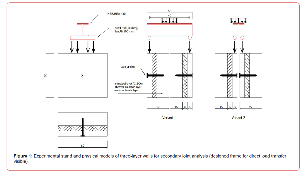
Two matrix configurations for testing were prepared Figure 1.
Ultimately, configuration 1 was chosen, considering the possibility
of lateral connection of the left and right matrices via anchoring
the load-bearing layers (using a flat bar and mechanical anchors to
the concrete), without affecting test results. The matrix dimensions
were limited to 60 x 50 x 27 cm (width x height x thickness), enabling
relatively easy handling of samples and avoiding geometric effects
of edge distance on the characteristic connector capacity  per standard [13].
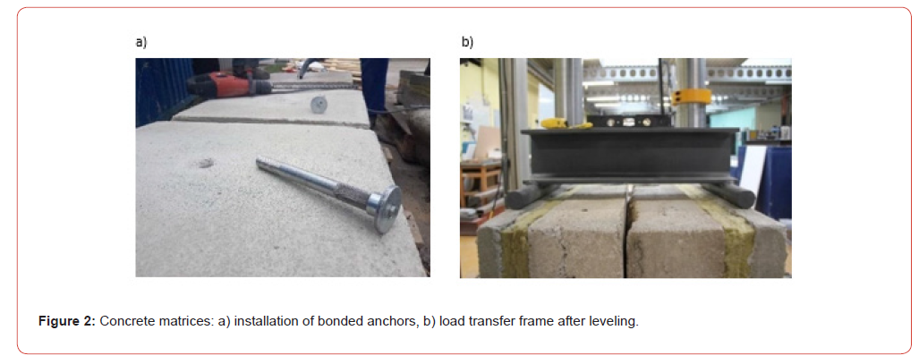
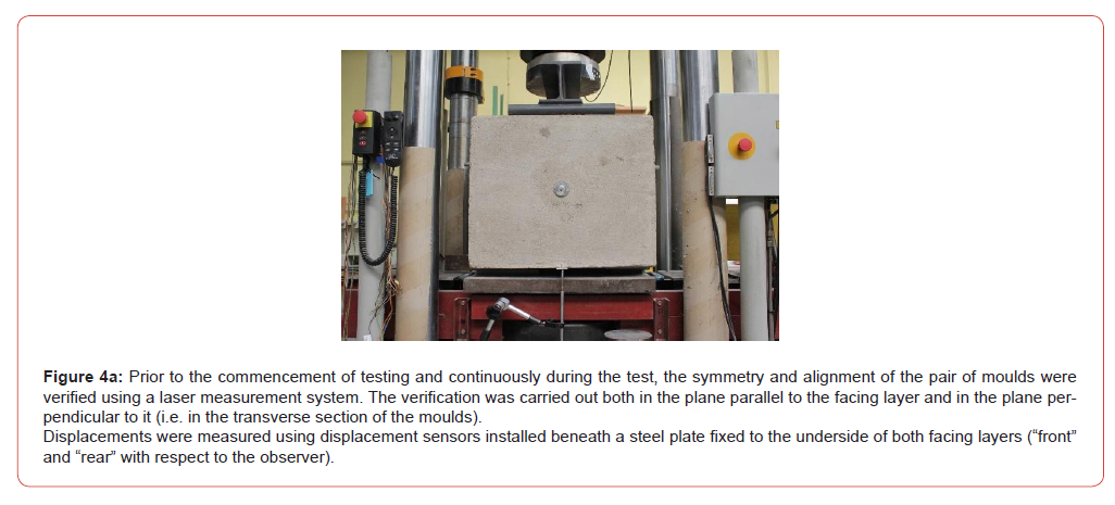
Force measurement was performed using the internal software of the Instron SATEC testing machine, and displacement was recorded using actuators and Catman software. This avoided inaccuracies related to the piston position, frame compliance, and load transfer. Figure 2 shows the concrete matrices and the load transfer frame at the prepared measuring station.
1 Approvals are now mostly withdrawn and replaced by ETA.
Material Variants of Concrete and Anchors
To determine the impact of material properties on the load capacity of secondary anchoring, the following variants were tested (Table 1):
- Testing three types of (bonded) anchors:
• threaded rod,
• K2 anchor,
• two Copy-Eco anchors;
- Testing of two anchor configuration variants:
• single threaded rod,
• double threaded rod
- Testing of four variants of the facing layer concrete:
• normal-weight concrete, class ≥ C12/15 (approx. C16/20)
• normal-weight concrete, reduced strength, class < C12/15
(approx. C12/15)
• lightweight expanded clay aggregate concrete, class ≈ LC 16/18
• lightweight expanded clay aggregate concrete, reduced
strength, class ≈ LC12/13
Table 1:Variants of tested concrete matrices and anchoring systems.

To determine the concrete class from the prepared mixes, three cubic samples were taken for strength testing after 28 days. After determining the compressive strength of the cubic samples, the following was established:
- for the planned class C12/15: 𝑓ci = 14,3; 𝑓cm = 21,6 [N/mm2] - for the planned class C16/20: 𝑓ci = 16,1; 𝑓cm = 25,8 [N/mm2] - for the planned class LC12/13: 𝑓ci = 10,1; 𝑓cm = 18,1 [N/mm2] - for the planned class LC16/18: 𝑓ci = 22,3; 𝑓cm = 24,8 [N/mm2]
Both standard criteria for the assumed concrete classes were thus met. The measured average values of concrete density were:
- Normal-weight concrete C12/15 and C16/20: 2332 kg/
m3
- Lightweight aggregate concrete LC12/13 and LC16/18: 1375
kg/m3
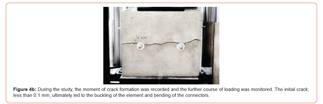
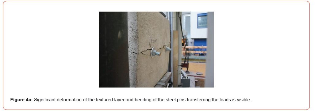
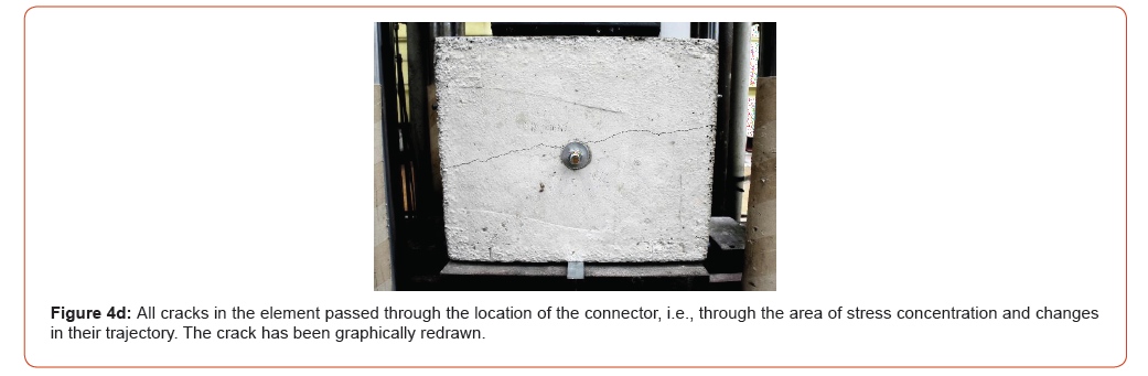
A significant “weakening” from the perspective of studying the impact of material properties on the parameters of secondary anchoring is the cracking of the textured concrete layer (some manufacturers allow the use of bonded anchors in cracked concrete). It was decided not to prepare separate cracked matrices, but to take advantage of the occurrence of cracks during loading, and the possibility to observe the behavior of the sample (the ability to transfer loads and the progress of displacement between layers) both before and after cracking.
Measurement Results
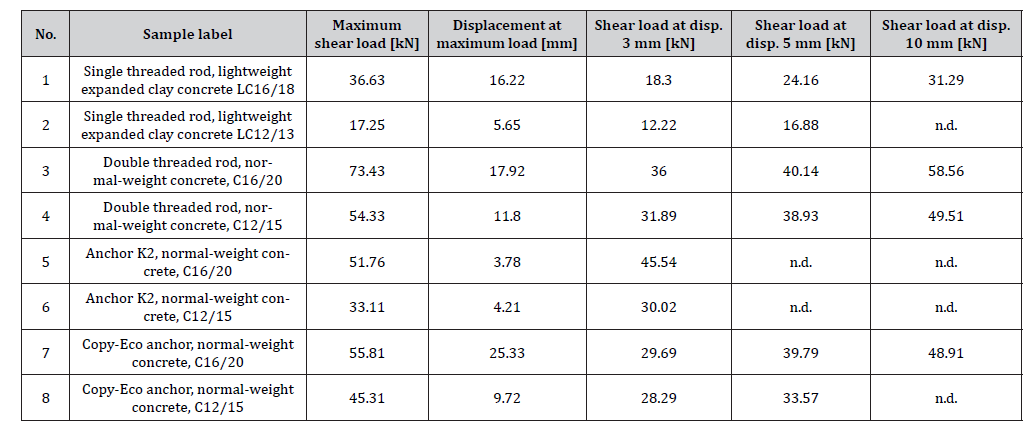
In accordance with the adopted testing procedure, each pair of concrete matrices was successively loaded and their displacements were measured. During the gradual loading of the samples, observations were made and significant material behaviours were recorded: the technical condition of the concrete was verified, including any cracking, spalling or deformations. During the study, the load was measured for selected values of displacement of the textured layer relative to the load-bearing one: 3, 5 and 10 mm. The maximum load carried by the secondary connection was also indicated - measured at the moment of failure of the connection or a sudden change in load (e.g. when a fragment of the matrix rested against another element of the test rig). The table below (Table 2) presents the direct measurement values for the pairs of concrete matrices.
Table 2:Direct results of load and displacement measurements for the tested pairs of concrete matrices
Combined load-displacement graphs for each pair of matrices are provided below Figure 3. The data are illustrated for concretes of class LC16/18 and C16/20.
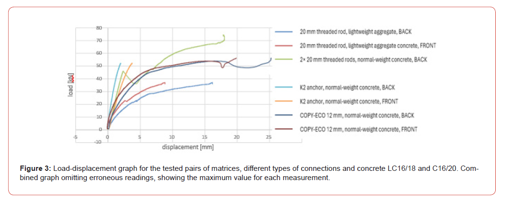
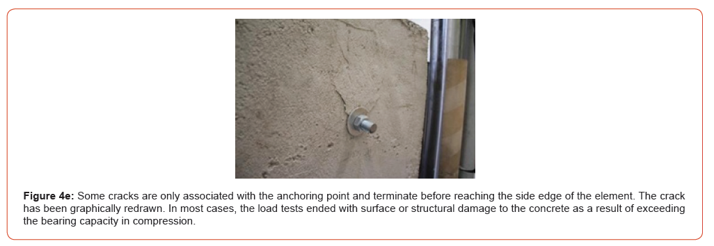
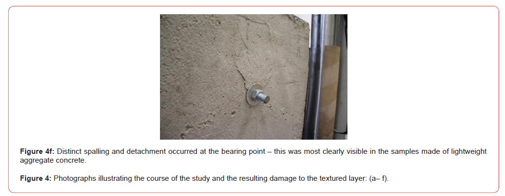
Table 3 summarises the corrected results for a single matrix and a single connection, taking into account the self-weight of the textured layer and the load-transfer frame. The load from the thermal insulation layer of the sample, which is only partially transferred by the textured layer, was omitted from the recorded loads. During the measurements, any cracks that appeared (indicating a change in the working conditions of the sample under test) were recorded. A series of photographs and video recordings were taken, the axes of symmetry of the set-up were checked and deviations and deformations were measured. Below are some of the photographs which, together with commentary, supplement the above results (Figure 4).
Table 3 summarises the corrected results for a single matrix and a single connection, taking into account the self-weight of the textured layer and the load-transfer frame. The load from the thermal insulation layer of the sample, which is only partially transferred by the textured layer, was omitted from the recorded loads. During the measurements, any cracks that appeared (indicating a change in the working conditions of the sample under test) were recorded. A series of photographs and video recordings were taken, the axes of symmetry of the set-up were checked and deviations and deformations were measured. Below are some of the photographs which, together with commentary, supplement the above results (Figure 4)
Calculation Verification of Obtaineg Results
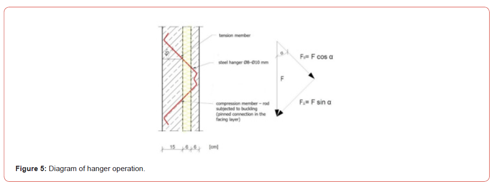
Due to the differing work scheme and distribution of forces of secondary fixings, compared to the original hangers, the calculation approach also varies (Figure 5). The hangers were to be calculated in accordance with [14]:
1. Verification of the load-bearing capacity for tension in the
upper arm,
2. Verification of the load-bearing capacity of the compressed
arm, taking buckling into account,
3. Verification of the load-bearing capacity under complex stress
conditions,
4. Verification of the anchorage calculation for the hanger.
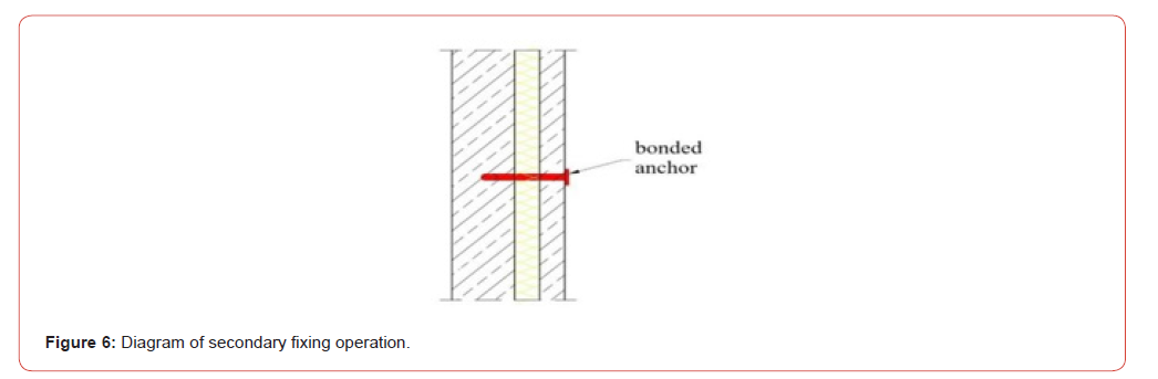
In the case of secondary connectors (most often in the form of
dowels mounted perpendicularly – see Figure 6), the calculation
verification of the connection should cover the failure mechanisms
as specified in [13, 15], listed below:
1. Verification of connector capacity: shearing under eccentricity
and possibly tension;
2. Concrete failure: cone pull-out (including combined connector
pull-out), splitting, chipping due to shear force;
3. Control of connector deflection (determining admissible 𝛿).
Additionally, due to the arrangement of layers in the three-layer wall and, consequently, the specific “suspension” of the textured layer and its entire weight on the connector, it is necessary to verify the bearing capacity for compression of the concrete in the textured layer (above the connector).
Wind loads are often disregarded, as tensile load in horizontal connectors is never the deciding factor for not meeting the ultimate limit state. Similarly, calculation examples for various types of anchors and load values indicate that the condition related to concrete failure under shear is also not decisive. Thus, the key criteria for verifying the secondary connection are: connector capacity for shear with eccentricity, the connector deflection criterion, and concrete bearing capacity under compression. In the case of a two-anchor system (with an oblique anchor), the above conditions are identical, except that wind load must also be considered due to the direction of the resultant force. To verify the laboratory measurements obtained (on matrices), calculations may be limited to the deflection criterion and the concrete bearing capacity under compression.
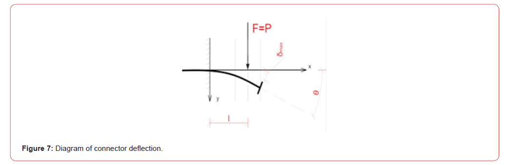
The deflection of the steel pin can be checked by calculation, using the basic formula derived from the differential equation for the deflection line of a cantilever beam (see Figure 7):

After transformation (using Clebsch’s method, integration), the simplest form of the equation for deflection at any point is obtained:

and the maximum deflection at the end of the beam 𝛿max (3). In turn, the equation with respect to EI is:

2 This is an additional verification with respect to standard [13].

where:
𝐸 - Young’s modulus (e.g. for steel 316L (1.4404) = 200 [GPa],

𝑃 – loading from layers acting on the pin
𝑙 – cantilever length of the pin = h i + 0.5 h f (thickness of the
insulation layer + 0.5 thickness of the textured layer),
𝛿max – maximum deflection at the end of the beam
Sample calculation results for deflection of the tested pins under the assumed force, along with a comparison to the measured values, are shown in Table 4. Due to the location of the displacement sensors outside the plane of the slab, formula (2) was used: x = l + 0.03 + 0.03 [m] was assumed.
In Figure 8, it can be seen that significant discrepancies in the analytical method concern mainly displacement values above 3 mm, and most notably above 5 mm, that is, at the moment when the first damage to the concrete itself occurs.
Table 3:Results of load and displacement measurements for a single matrix and single connection (including the self-weight of the textured layer and test set-up).
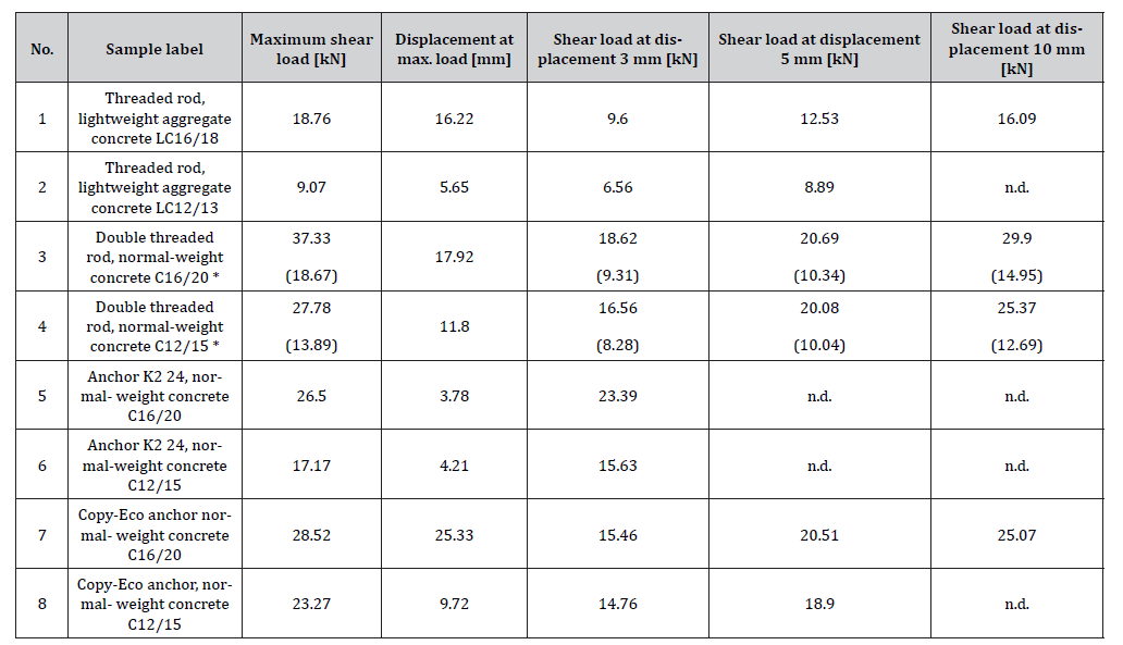
* Values in brackets refer to the load per single rod
Table 4:Differences in measured and calculated displacements - horizontal anchors.
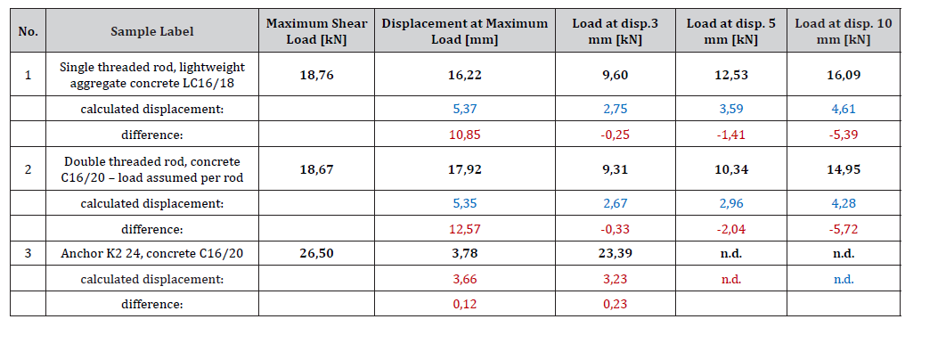
To determine the displacement of the Copy-Eco anchor, a model prepared in Soldis PROJEKTANT software was used. The material parameters were set for steel (1.4404), facing layer concrete (C16/20), and wool (CS(10) = 70 kPa). The horizontal bar was omitted due to its low stiffness, and thus significant susceptibility to deformation under vertical force.
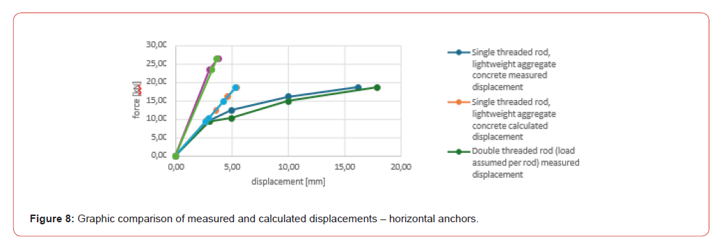
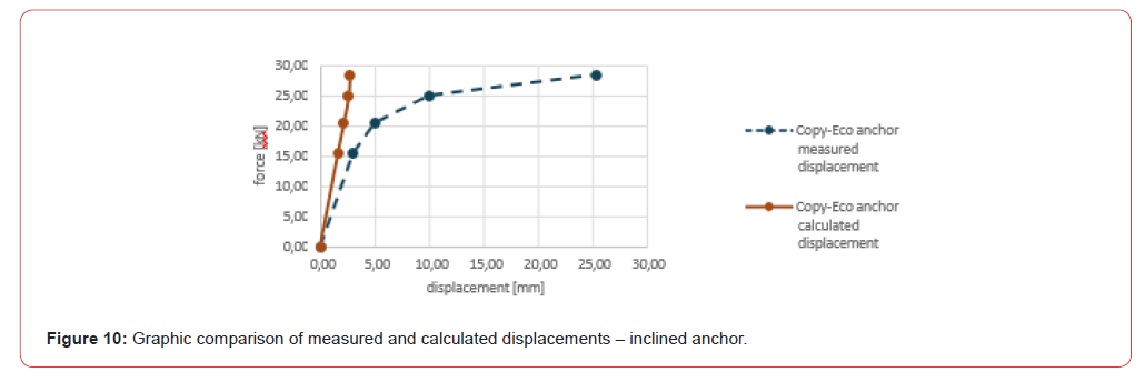
Table 5 and Figure 10 present a comparison of the measured and calculated displacement values for the diagonal anchor.
The significant differences in displacement values (particularly in the final phase of loading) are likely due to assembly tolerances associated with the diagonal installation of the anchor, nuts, and washers, as well as exceeding the local load-bearing capacity of the concrete.
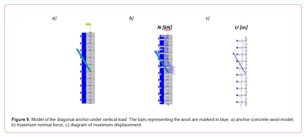
Table 5:Differences between measured and calculated displacements - diagonal anchor.

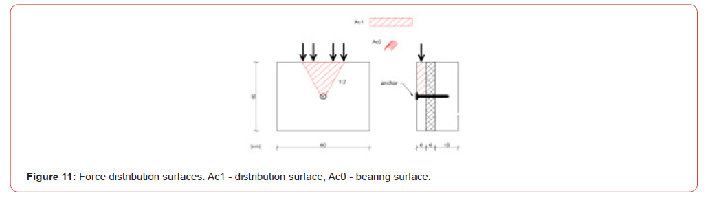
The criterion for concrete compressive strength is related to the distribution of stresses as a flow of forces in accordance with the Saint-Venant principle. Additional tensile stresses arise, which result in diagonal cracking in the vicinity of the anchor, thereby significantly limiting the connection’s load capacity. Figure 11 illustrates a biaxial stress state (the loaded area increases only in one direction), and thus the stresses in the concrete should be limited according to the formula for σRd,max as per standard [16], as for a compressed node:

where:
𝑘1 – value adopted according to [16], the recommended value
is 1.0;
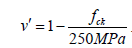 reduction factor for cracked concrete strength
according to [16];

Taking the above into account, the bearing capacity under compression should be determined from the following formula:

where:
𝐴𝑐0 – bearing (compression) area (in our case: π ∙ 𝑟 ∙ ℎ𝑓)
This means that for concrete class C12/15 and a surface area 𝐴𝑐0 = 0,00226 𝑚2 (anchor ∅ 24) we obtain the value σRd,max = 8,16 𝑀𝑃𝑎 a FRdu ≤ 18,46 𝑘𝑁. For concrete C16/20, this will already be FRdu ≤ 24,20 𝑘𝑁. According to Table 7, it is apparent that for at least one type of anchor (“K2”) the bearing capacity under compression will be exceeded. With a significant reduction in concrete strength (C8/10) FRdu ≤ 12,51 𝑘𝑁. Interestingly, with an anchor of ∅ 20 mm, concrete class C16/20, and a reduction of the facing layer thickness by 0.5 cm (to 5.5 cm), the bearing capacity under compression will, according to calculations, already be exceeded in all cases from Table 7. The system component also includes an adhesive in the form of epoxy resin, but its compressive strength of approximately 110 MPa and tensile strength of approximately 80 MPa are so significant that they do not constitute a critical factor in verifying the load-bearing capacity.

And when recalculated for the surfaces of sample panels, the values obtained are as shown in Table 6.
Table 6:Design action from self-weight on the connectors of sample panels and a single connector when two are used per panel (minimum requirement).

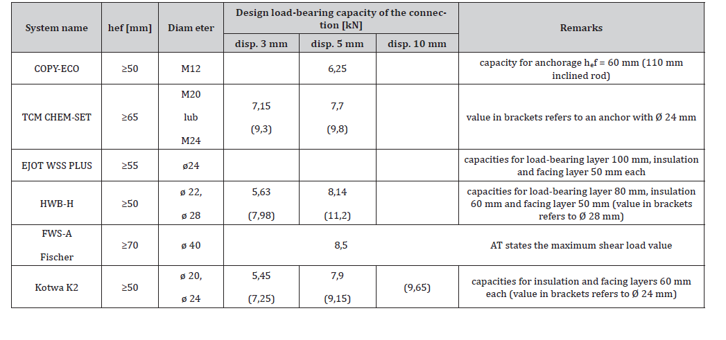
As can be seen, there is a risk of exceeding the compressive capacity if the concrete class is not properly specified (detailed data can be found in the authors’ article [19]). Below (Table 7), for comparison, are the capacities of connectors according to Technical Approvals of the manufacturers.
Table 7:Design capacities of connections between the facing layer and the load-bearing layer for a single connector, assuming the facing layer concrete is at least class C12/15 - data based on [4-6,20- 22].
3 “If various but statically equivalent loads are applied at a certain point of a body, only in the vicinity of that point will the stresses differ, and in the rest of
the body the method of applying the stresses will not affect their distribution” – encyklopedia.pwn.pl
4 Formula 6.60 of EC2 standard [16]
In each case, the value is limited to a single connector (not a set of two, as is often given in Technical Approvals). Importantly, the values below do not take into account the requirements contained in standard [13], which was issued after most of the currently used system solutions were introduced to the market.
Summary
The conducted studies of secondary connections in multilayered external walls of large-panel buildings confirmed a partial convergence of experimental results with computational ones (especially for layer displacements up to 3 mm). The research also indicated that the selection of remedial systems for secondary fixing depends on the assessment of the quality, defects, and degradation of individual wall elements, with particular emphasis on the thickness of the facing layer (hf) and insulation layer (hi), as well as the compressive strength of the facing layer concrete (fck). The diameter of the anchor was chosen as the decision criterion when selecting the anchoring system, as it directly affects not only the deflection (𝛿max), but also the area of the concrete bearing zone (Ac0). Furthermore, diagnostic investigations revealed considerable variability of the aforementioned parameters in the analysed buildings, and even in individual elements.
It proved particularly significant that, for lower concrete classes and thinned facing layers, the bearing capacity under compression was exceeded at relatively small displacements, highlighting the need for a precise assessment of the technical condition and appropriate selection of fixing systems.
As part of broader research, a diagnostic algorithm for threelayer walls was developed, enabling the determination of basic requirements for the remedial system, such as permissible deflection and anchor diameter, taking into account the technical condition of the elements. In cases of exceptionally good results, it is suggested to forgo reinforcement (many buildings are reinforced as a matter of course, without technical condition assessment), while for extremely poor parameters, the recommended solution is to dismantle the wall layers. A summary of the required checks for bonded anchors according to standards was also drawn up, together with their adaptation for use in existing three-layer walls.
Acknowledgements
None.
Conflict of Interest
No conflict of interest.
References
- Jasiczak J, Girus K (2017) Maintenance and Durability of the Concrete External Layer of Curtain Walls in Prefabricated Technological Poznan Large Panel System, IOP Conference Series: Materials Science and Engineering 245(3).
- Krentowski J, Knyziak P, Mackiewicz M (2021) Durability of interlayer connections in external walls in precast residential buildings, Engineering Failure Analysis, tom Vol. 121.
- Wójtowicz M, Możaryn T (2013) Stan techniczny złączy i prefabrykatów budynku wielkopłytowego po 40 latach eksploatacji, in: Awarie budowlane: zapobieganie, diagnostyka, naprawy, rekonstrukcje. XXVI Konferencja Naukowo-Techniczna, Szczecin-Mię
- (2009) Aprobata techniczna: AT-15-6916/2009: Łączniki wklejane Copy-Eco do wzmacniania betonowych ścian warstwowych (Koelner), ITB, Warszawa.
- (2015) Aprobata techniczna: AT-15-6173/2015: Łączniki wklejane HWB-H do wzmacniania betonowych ścian warstwowych (Hilti AG), ITB, Warszawa.
- (2013) Aprobata techniczna: AT-15-8130/2013 Stalowe łączniki wklejane K2/2008 do wzmacniania prefabrykowanych ścian warstwowych budynków wielkopłytowych. ITB, Warszawa.
- (2021) PN-EN 206+A2:2021-08: Beton - Wymagania, właściwości, produkcja i zgodność. PKN.
- Szlendak JK, Jabłońska-Krysiewicz A, Tomaszewicz D (2018) Analitical modelling of a three-layer wall system of strengthening for large-panel slab buildings by means of bonded anchors in: MATEC Web of Conferences - 3rd Scientific Conference Environmental Challenges in Civil Engineering (ECCE 2018).
- Gara F, Ragni L, Roia D, Dezi L (2012) Experimental tests and numerical modelling of wall sandwich panels. Engineering Structures 37:193-204.
- Huang JQ, Dai JG (2019) Direct shear tests of glass fiber reinforced polymer connectors for use in precast concrete sandwich panels, Composite Structures, tom 207(4):136-147.
- Naito CJ, Hoemann JM, Bewick BT, Hammons MI (2009) Evaluation of shear tie connectors for use in insulated consrete sandwich panels. Interim Report. Air Force Research Laboratory, United States.
- Baryłka A, Tomaszewicz Tomaszewicz D (2020) Influence of surface shape of glued anchors on their load capacity Modern Engineering pp. 78-82.
- (2018) Norma: PN-EN 1992-4:2018: Eurokod 2 - Projektowanie konstrukcji z betonu. Część 4: Projektowanie zamocowań do stosowania w betonie.
- Henclewski T, Pogorzelski A (1990) Nowelizacja Instrukcji wykonywania połączeń w prefabrykatach betonowych ścian warstwowych dla budownictwa mieszkaniowego, Warszawa: Centralny Ośrodek Badawczo-Projektowy Budownictwa Ogó
- Konieczny K (2002) Dodatkowe połączenia warstwy fakturowej z warstwą konstrukcyjną wielkopłytowych ścian zewnętrznych. Budynki wielkopłytowe - wymagania podstawowe., Warszawa: ITB.
- (2008) Norma: PN-EN 1992-1-1: Eurokod 2. Projektowanie konstrukcji z betonu. Część 1-1: Reguły ogólne i reguły dla budynkó
- (2004) Norma: PN-EN 1991-1-1: Oddziaływania na konstrukcje. Część 1-1: Oddziaływania ogó Ciężar objętościowy, ciężar własny, obciążenia użytkowe w budynkach.
- (2008) Norma: PN-EN 1991-1-4: Oddziaływania na konstrukcje. Część 1-4: Oddziaływania ogó Oddziaływania wiatru, PKN.
- Girus K, Jasiczak J, Kanoniczak M (2025) Multi-criteria Analysis of the Selection of Secondary Anchors for the Modernization of Multi-layer External Walls in Existing Large-panel Buildings. In: Proceedings CAUSummit.
- (2016) System kotwienia CHEM-SET Trutek, Sękocin Nowy: Trutek Fasteners Polska Sp z o.o.
- (2020) Krajowa Ocena Techniczna: ITB-KOT-202/1373: Kotwy mechaniczne ze stali nierdzewnej EJOT WSS PLUS do wzmacniania betonowych ścian warstwowych, ITB.
- (2018) Catalogue Fixing Systems: The economical solution for the repair of triple-skin outer wall, Fischer.
-

This work is licensed under a Creative Commons Attribution-NonCommercial 4.0 International License.