 Research Article
Geotechnical Perspective of the Causes of Cracks in Building of University Campus (Sindh University Jamshoro Sindh Pakistan)
Mushtaque Amed Pathan1*, Maryam Maira2, Arif Khaskheli3 and Agha Jamshed4
1Center for Pure & Applied Geology, University of Sindh, Jamshoro
2Institute of Environmental Engineering & management, Mehran University Jamshoro
3Material Engineer, Prof. Dr. G.B Khaskheli Civil Engineering Lab. Jamshoro
4Deparment of Architecture Engineering Mehran University Jamshoro
Mushtaque Amed Pathan, Center for Pure & Applied Geology, University of Sindh, Jamshoro, Pakistan.
Received Date: May 10, 2021; Published Date: July 02, 2021
Abstract
Building construction throughout the world faces defects from normal to heavy and destructive like cracks and fractures which cause damages and finally collapse to heavy life losses along with economical and financial. The crack-like structures are found in walls and columns also. For the purpose of study, the international experts have classified the smallest allowable standards of these defects which may not be harmful to buildings and people living there. This research study has been carried out to investigate the main reasons to investigate the causes of cracks in newly completed and used buildings in where some distinct cracks appeared immediately and after some years. Often these cracks seem almost in walls and other structural elements such as columns and beams, with different patterns. The general methods consisting of reconnaissance survey; building inspection and laboratory testing were used to investigate the causes of these detrimental cracks. By the use of a reconnaissance survey, factors that may lead to the formation of cracks were considered and analyzed. The width, pattern, and conditions of the cracks were identified during the building inspection stage and the soil properties related to the creation of cracks were determined during the laboratory test. Based on the outcome of the study; there is no evidence of factors such as a matured system that may lead to the creation of cracks in the building; all the cracks are active cracks with their width increasing with time and the soils in the entire block of the building possessed high percentage of fine materials with high moisture content and plasticity indices. The pore water pressure in this type of soil takes a long time to vanish, which can be expressed by the very low value of the coefficient of permeability (1.90x 10⁻⁷ to 2.15 x 10⁻⁷ m/s) acquired from different soil samples collected from the study area. Hence the cracks in this type of buildings were found to be caused by the settlement of the building due to the nature of the main soil type that was found in the study area.
Keywords:Buildings; Cracks; Plasticity indices; Coefficient of permeability; Porewater Pressure; Moisture content; Differential settlement
Introduction
The natural defects like cracks, fractures, and load settlements are the general causes of Building collapses everywhere in the world. In Pakistan, this menace is also devastating many small and large buildings in many parts of the country [1]. As result, the loss of lives, severe injuries, and huge economic losses like factors appear [2]. This problem of building collapse in our country generally occurs due to the use of substandard ratio of the material in mortar and concrete, low and improper depth of foundation by some unprofessional contractors, etc. Along with natural hazards such as floods, design flaws, and aging of buildings with time. As a common practice of corruption, lawlessness, and presumptions that any professional in the built environment can assume all forms of responsibility in a building process without the basic skill required for it are considered as another particular cause that commonly causes building failure [3]. According to the size, complexity, and purpose of a particular building project; the practice of designing, constructing, and operating buildings is usually a collective responsibility of different professionals and trades of construction industry [4]. The inexpertness or lack of professional knowledge one or more of those professionals may result in a faulty structure which can metamorphose into catastrophic failure. Building collapse rarely occurs without a sign; and the sign of failure in the building usually include deflection of structural members and appearance of unacceptable cracks in some parts of the building, and if no proper attention is paid to inspect these problems; it may show some part of the whole structure unfit for its planned purpose [5]. The fractures or cracks are generally considered as an irregular and complete or incomplete separation of the concrete into two or more parts, produced by breaking or fracturing as a result of the strains that make tensile stress in excess of the capacity of material’. The incurred defects or cracks present in concrete and building walls is an intrinsic feature, which cannot be completely prevented but can only be controlled and minimized by engineering techniques [6].
The fissures or cracks are generally classified into two major groups: the structural cracks and non-structural cracks [7]. Structural cracks are of serious concern and should be studied, monitored, and rehabilitated by professionals as they can affect the stability of buildings and the damage can be real. Some structural cracks are caused by many reasons, and they include the settlement of the foundation, deformation of the structure due to overloading or design deficiency, poor construction methods/faults in construction work, the movement of the ground such as ground upheaval and landslide, etc. Similarly, non-structural cracks are cracks that do not harm the stability of the structures, and they usually result from poor concrete mix, poor workmanship, and construction methods, improper or non-construction joints and poor structural detailing [8]. On the basis of movement or increase in size; Cracks can further be classified into active and dormant cracks and the difference between an active or working crack and a permanently inactive crack or fracture is considered as the active crack can open or close and get longer, but a dormant crack has stopped moving. The expert idea is of great importance to differentiate between these cracks before applying appropriate solutions to the problem [9]. Some soils experienced for engineering purposes may have shrinkage/swelling potentials and this property of soils leads to the settlement of structures, the shrinkage/swelling potential of soil is controlled by the clay content and its plasticity. Because of that is clayey soils have a high liquid limit and plasticity indices. Different factors cause to foundation settlement, and which include vegetation, groundwater lowering, temperature changes, seepage and scouring, mining subsidence, loss of lateral support, etc. [10].
For the assessment purpose, it is very important to study the causes of cracks in the building; the necessary limits to find are its place, pattern, width, length, depth, age and whether it is in action or not, how dangerous it is and what needs to repair it [6]. BS 8110 (1997) [8] is the specification of the most allowable width of cracks in structural elements as 0.3mm and 0.1mm for water retaining structures. The famous engineer Burland and Day, 1977 provided Classification of cracks based on visual damage to the walls as presented in table 1 (Table 1).
Table 1:Classification of cracks based on visual damage to walls.
The repair work was completed in the buildings of the study area were repair before handing over of the building to the different Faculties of and after the buildings were occupied; but still, the cracks continue to exist. Therefore, this study has been carried out to know the root causes and precautionary measures to be taken for the safety of students and staff.
Methodology
The study area
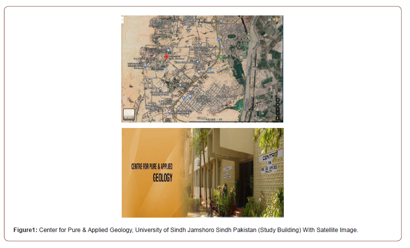
The study was conducted at the Faculty of Natural sciences (various departments) University of Sindh Jamshoro Pakistan. The buildings one story and housed the Center for pure & Applied Geology, classrooms, admin offices, labs, etc. This building is in a flat, low terrain with an upper layer of hard nodular limestone, while the underlying soil is a loose shale with silty clay material. It is located at Latitude 25025’12.62” N and Longitude 68015’41.86” E. Figure 1 depicts the location of the study area. The construction of the building started in 2002 and it was commissioned and handed over to the faculty on March 27th, 2006 (Figure 1).
The study was conducted in three phases; the reconnaissance survey; the building inspection and laboratory testing of soil samples collected from the study area. The reconnaissance survey was the primary purpose of studying the immediate environment of the building in the target. Grown trees and drainage systems around the vicinity of the structure were analyzed with respect to their influence on the crack development on the building. Four to five-spot points were selected during this phase of the study from where soil samples were collected for laboratory testing then the building inspection was carried out to diagnose the cracks in the building. Their location, width, depth, and orientation pattern of samples for investigation have been identified and measured using the standards of building inspection. Measuring tape and, protractor was used for this purpose. The laboratory tests for soil were conducted on five soil samples taken from five trial pit dug in the study area. These trial pits are denoted by STP1, STP2, etc. are denoting the trial pits no 1, trial pit no 2 and so on. The standard depth of soil samples was 1 to 1.5 m from where the samples were collected, and six laboratory tests were conducted on each sample. The tests were conducted based on the standard procedure and specifications given in BS 1337 (1990) [11]. Details of the procedures for these tests are outlined in that standard.
The laboratory tests for soil samples t conducted were categorized into; physical (index) and engineering properties tests. The tests for physical properties were conducted for the soil classification purpose in order to predict the engineering properties of the soils. These tests include determination of particle size distribution, Atterberg limits, and Specific Gravity tests. They were conducted according to the specified procedure outlined in British Standard, BS 1337 Part 2: 1990 (BSI, 1990). The permeability and the consolidation tests were conducted as the engineering properties tests. BS 1337 Part 5: 1990 while the Consolidation test in accordance with BS 1337 Part 6: 1990 for the Permeability test [11].
Results and Discussions
Reconnaissance survey
On the basis of the preliminary survey conducted the result indicates that the building was constructed on a nodular limestone highly fractured formation is overlying soft Shales capped with thinly laminated silt and clay. There are some grown trees near the building which can influence the beginning of the cracks and all the seepage systems within the building, areas are little lawns and gardens. Therefore, the cracks in the building are caused by ingress of tree roots in the building or because of water penetrating into the ground due to lack of proper natural cracks present in the geological formation sequence.
Building inspection
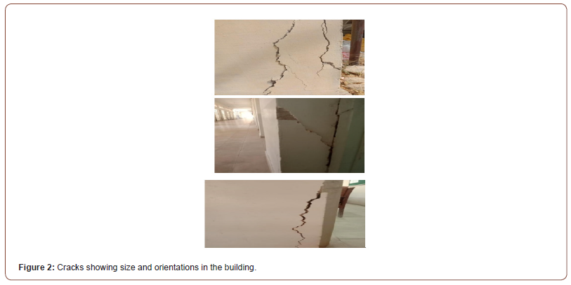
As the second phase of the building inspection was carried out by measuring the width, length, and orientation of the cracks. Therefore, starting at the beginning of the study the length and width of the cracks were marked and monitoring activities were continued from time to time to see whether these two parameters increase with a gap of time or not. The monitoring process of the cracks indicated that the cracks in the building are active cracks shown by the appearance of new crack edges during the building inspection. The majority of these cracks are classified as very severe categorized as stability cracks with an average width greater than 20 mm [8] in the foundation walls and greater than the specified 0.3mm on the columns, beams, and the staircase slab. This is very alarming when compared with the maximum acceptable value given by Burland and Day and in BS8110. These cracks are more dreadful on the left-hand side of the building which has more loading compared to the right-hand side of the building, same as on the ground floor of the building than on its first floor. These cracks are fastly increasing in depth and width caused by the settlement of the foundation soil and the possible sliding of some parts of the foundation [4]. The horizontal cracks are wide and of constant width throughout their lengths and seem to have occurred at the same time possibly caused by excessive settlement as a result of poorly constructed foundation and poor workmanship. Diagonal cracks have also emerged from the corners of beams pocket, door, and windows edges, and the vertical ones were identified. They may be caused by the gradual vertical movement of the foundation and concrete shrinkage. The slab and some of the columns also suffer severe cracks extending through the walls possibly caused by; an uneven settlement in the foundation soil putting the building under tension. Figure 2 shows some of these cracks (Figure 2).
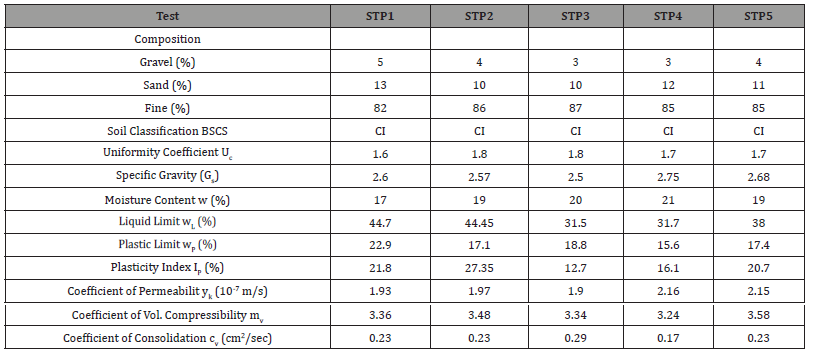
The laboratory tests for soil were conducted on both disturbed and undisturbed soil samples collected from the site at a depth of 1 to 1.5m near the ground surface. The results of the test result are presented in Table 2 (Table 2).
Table 2:Laboratory soil test results.
Index properties and soil classification
A number of index property tests were conducted on the soil samples collected from the site. The soil classification was the main physical index property of the soils investigated in this study, depends on several factors such as the Atterberg limits, specific gravity, and particle size distribution. Figure 3 shows a typical particle size distribution of the soil sample collected from the site. The plasticity index (PI) of the soils was plotted above the A-line [12,13] which is the range of clayey materials. Therefore, based on the British Soil Classification System (BSCS), the soils are classified as clayey soils of intermediate plasticity (CL). The particle size distribution tests indicate that the foundation soil contains a high percentage of fine material ranging between 78.18% and 85.57% as indicated by the high plastic nature of the soil. And, from Table 2, the liquid limit of the soils from the study area ranges between 28.6% and 45.7%; while the plastic limit ranges from 12.3% to 20.8%. The natural moisture contents (wn) of the soil samples from the study area vary between 16% and 21%, which is relatively high considering that the experiment was conducted in the month of April is the peak of the dry season in the region. The specific gravity of the soil ranges between 2.60 and 2.70 which are typical values for clayey soils (Figure 3).
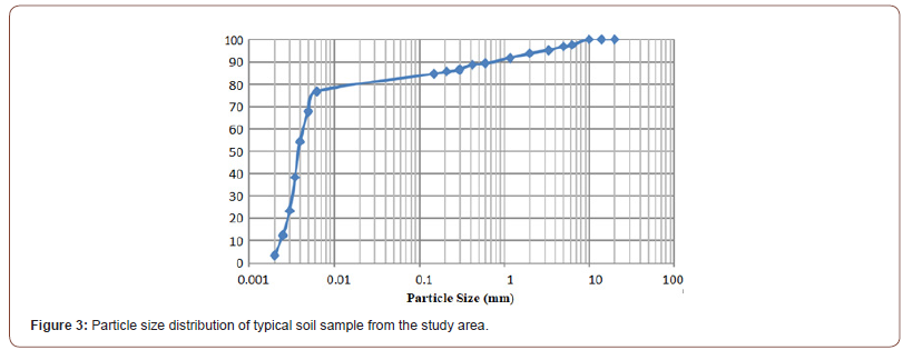
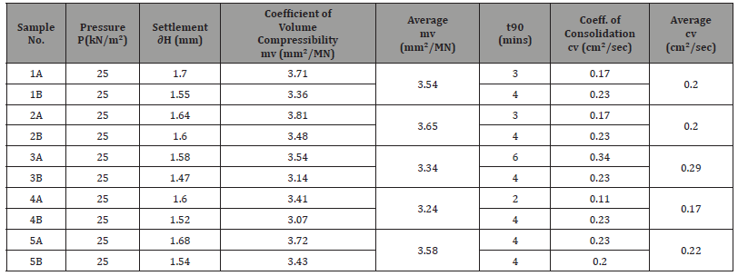
Table 3:Coefficient of consolidation and volume compressibility.

Engineering properties
The coefficient of permeability obtained from falling head permeability test and the coefficient of consolidation and volume compressibility obtained from one-dimensional consolidation tests are the engineering properties of the soils investigated in this study. The settlement of the foundation is related with The properties of the soils to the summary of the results is given in Table 2 and the detailed results of the one-dimensional consolidation tests are presented in Table 3. The coefficient of permeability of the soils is the rate of flow of water per unit area of soil under a unit hydraulic gradient, and it controls the strength and deformation behavior of soils. The value of the coefficient of permeability obtained from the soil samples collected from the study area ranges between 1.90 x 10⁻⁷m/s and 2.15 x 10⁻⁷ m/s. These values are typical values of permeability of clayey soils [12]. Because of the lower hydraulic conductivity value of the soils, the rate of disappearance of excess pore water pressure on loading was slower. The final results of a structure built over-saturated clay and is the gradual reduction in the volume of a fully saturated soil of low permeability due to seepage of some of the pore water is because of consolidation settlement. The coefficient of volume compressibility is used to evaluate consolidation settlement. The results of the consolidation tests anticipate that the foundation soils have high coefficient of volume compressibility [13], mostly found in organic alluvial clays (with Mv˃1.5m²/MN) (Table 3) (Figure 4).
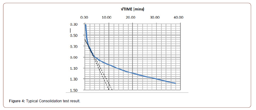
Figure 4 shows the coefficient of consolidation was determined using the square root of time method and a typical result of this test. The coefficient of consolidation of the soil lies between the range of 0.23cm²/sec and 0.34cm²/sec which is considered relatively low. This is an indication of the poor hydraulic conductivity of the soil; so, the soil will continue to reduce in volume over a long period of time after the rapid settlement and maybe several times greater than the immediate settlement [14-16].
Conclusion
Keeping in view the results of the crack analysis; their shape, width and orientation and the results of the soil test conducted on the soil sample from the study area it has been concluded that;
1. The subsurface strata comprise a relatively thin top layer of shale deposit along with silty and clayey soil. This is underlain by alluvial deposits of silty clay which is capped with nodules of limestones and grit most probably.
2. The cracks are very severe containing active and dormant, influencing the structural formation of the building, which is caused by soil consolidation under the footings and the foundation walls; differential settlement of the building as a whole and a poor foundation design and/or construction method.
3. The soil in the foundation contains a high amount of clay with high plasticity and poor hydraulic conductivity.
Acknowledgment
None.
Conflict of Interest
No conflict of interest.
References
- G Wagner, R Lima, R Sampaio (2021) Modal identification of a light and flexible wind turbine blade under wind
- ZF Fu, J He (2001) Modal Analysis (1st), Butterworth-Heinemann, Jordan Hill, Oxford, UK, p. 304.
- DJ Ewins (2000) Modal Testing: Theory, Practice and Application (2nd), Research Studies Press Ltd., Baldock, Hertfordshire, England, p. 576
- NMM Maia, JMM Silva (1997) Theoretical and Experimental Modal Analysis (1st), Research Studies Press Ltd., Taunton, Somerset, England, p. 488.
- R Brincker, C Ventura (2015) Introduction to Operational Modal Analysis (1st), John Wiley & Sons Ltd., Chichester, West Sussex, UK, p. 372.
- P van Overschee, BL de Moor (1996) Subspace Identification for Linear Systems: Theory Implementation Applications (1st), Kluwer Academic Publishers, Norwell, Massachusetts, USA, p 272.
- R Brincker, L Zhang, P Andersen (2000) Modal identification from ambient responses using frequency domain decomposition, Proceedings of the 18th International Modal Analysis Conference,
- G Wagner, D Foiny, R Lima, R Sampaio (2018) A new formulation of the SVMD with noise control and uncertainty quantification, Proceedings of the ICVRAM-ISUMA UNCERTAINTIES Conference,
- R Lima, R Sampaio (2018) What is uncertainty quantification? J Braz Soc Mech Sci Eng 40: 155.
- M Döhler, XB Lam, L Mevel (2013) Uncertainty quantification for modal parameters from stochastic subspace identification on multi-setup measurements, Mechanical Systems and Signal Processing 36(2): 562-581.
- KV Yuen, LS Katafygiotis (2003) Bayesian Fast Fourier Transform Approach for Modal Updating Using Ambient Data, Advances in Structural Engineering 6(2): 81-95.
- SK Au (2017) Operational Modal Analysis: Modeling, Bayesian Inference, Uncertainty Laws, Springer Nature, Beach Road, Gateway East,
- JMW Brownjohn, SKAu, Y Zhu, Z Sun, B Li, et al. (2018) Bayesian operational modal analysis of Jiangyin Yangtze River Bridge, Mechanical Systems and Signal Processing, 110: 210-230.
- Proceeding of the International Operational Modal Analysis Conference (2021).
- T Kijewski-Correa, DK Kwon, A Kareem, A Bentz, Y Guo, et al. (2013) Smart Sync: An Integrated Real-Time Structural Health Monitoring and Structural Identification System for Tall Buildings, Journal of Structural Engineering, 139(10): 1675-1687.
- FL Zhang, HB Xiong, WX Shi, X Ou (2016) Structural health monitoring of Shanghai Tower during different stages using a Bayesian approach, Structural Control and Health Monitoring, 23(11): 1366-1384.
- D Anastasopoulos, G De Roeck, EPB Reynders (2021), One-year operational modal analysis of a steel bridge from high-resolution macrostrain monitoring: Influence of temperature vs. retrofitting, Mechanical Systems and Signal Processing,161.
- S Bellizzi, R Sampaio (2015) The smooth decomposition as a nonlinear modal analysis tool, Mechanical Systems and Signal Processing 64-65: 245-256.
- G Wagner, D Foiny, R Lima, R Sampaio (2017) The robust smooth orthogonal decomposition method for operational modal analysis, Proceedings of the 17th International Operational Modal Analysis Conference,
-
Mushtaque Amed Pathan, Maryam Maira, Arif Khaskheli, Agha Jamshed. Geotechnical Perspective of the Causes of Cracks in Building of University Campus (Sindh University Jamshoro Sindh Pakistan). Cur Trends Civil & Struct Eng. 7(4): 2021. CTCSE. MS.ID.000670.
-
Buildings, Cracks, Plasticity indices, Coefficient of permeability, Porewater pressure, Moisture content, Differential settlement
-

This work is licensed under a Creative Commons Attribution-NonCommercial 4.0 International License.


