 Research Article
Fundamentals for Cracking Verification of Reinforced Concrete Structures
Maurizio Taliano, Department of Structural, Geotechnical and Building Engineering, Politecnico di Torino, Italy.
Received Date: March 03, 2021; Published Date: April 8, 2021
Abstract
A mathematical model, named as general method, has been set up to study the cracking behaviour of a concrete tie reinforced by ordinary bars, subjected to a monotonic load. The analysis is performed considering both the crack formation stage and the stabilized cracking stage. In particular, secondary cracks occur in the stabilized cracking stage, modifying the distribution of bond stress along the transmission length. As in the stabilized cracking stage the solution of the general method requires to carry out an iterative numerical procedure, for design purposes the maximum crack width can be determined through a simplified method that allows the main aspects of the structural behaviour to be taken into account.
Introduction
Cracking in concrete structures has to be considered normal and, in general, it does not indicate a construction defect or danger when it remains within limits established by standards or contracts [1,2]. Cracks, that can already occur in fresh concrete, are due to either direct loading or restraint or imposed deformations and appear when the tensile strength of concrete is reached. Two types of cracks can be observed in structural members, that means primary cracks, that propagate inside the concrete reaching the concrete surface, and secondary cracks or Goto cracks [3], that develop around the reinforcement bars remaining mostly inside the concrete. Limiting the maximum crack width is aimed at avoiding to impair the aesthetic aspects, also in order to not generating alarmism among people, and preserving the structural durability or the sealing capacity in case of tanks or retaining structures. To this regard appropriate limits of the crack width are introduced for the various service conditions, generally not exceeding 0.4 mm. In the following, the case of cracking due to loading is examined, as it is the most frequent case, and a mathematical modelling is proposed for the calculation of the maximum crack width in service conditions [4,5].
Stages of the Cracking Behaviour and Calculation Assumptions
Primary cracks occur in the tension chord of the structural members, where the steel reinforcement is located to control their spacing and width. For the sake of modelling, the cracking analysis of the tension chord is usually performed considering an ideal RC tie with an effective area, Ac,ef For instance, the height of the effective area of concrete can be assumed equal to 2.5 · (h − d), being h and d the height and the depth of the structural member, respectively. Here, the concrete tie is assumed to be reinforced by ns bars, with diameter ϕs and total area As, and subjected to an increasing axial force Fs. Three stages can be considered, that means:
1. The uncracked stage, where the tensile strength of the concrete, fct, is not reached and both concrete and steel present a linear elastic behaviour.
2. The crack formation stage, that starts when in a certain section the concrete tensile strength is overcome, and the first crack occurs. In this stage, when the axial force Fs increases, further cracks can form.
3. The stabilized cracking stage, where the crack pattern is assumed as completed and no new primary cracks can occur. In this stage, however, around the primary cracks, secondary cracks or Goto cracks [3] can form starting from the reinforcement and propagating into the concrete (Figure 1).
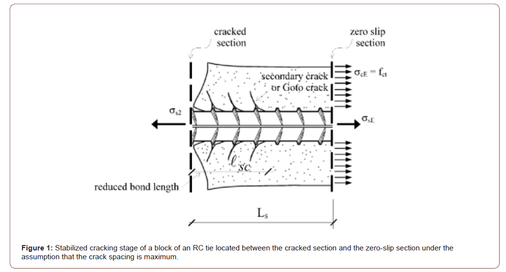
Because of cracking, around a single crack, during the crack formation stage, the state of stress obtained in the uncracked stage is modified, the assumption of perfect bond is lost, and a redistribution of stresses can be observed. In effects, in the crack formation stage, bond stresses, τbs, that are correlated to the slips between steel and concrete, are transmitted at the interface between steel and concrete. In this way the concrete stress, that is null at the cracked section, can increase until it reaches the concrete tensile strength, fct. Or the steel stress decreases from the cracked section to the zero-slip section. The distance, from the cracked section, where the concrete tensile strength, fct, is reached, is named transmission length, Ls. As far as the distribution of slip between steel and concrete along the transmission length, Ls, in the crack formation stage slip presents an analogous distribution of bond stress, that means slip is maximum at the cracked section and null at the zero-slip section. In effects, in the crack formation stage slips influence the bond stresses, through the bond law, along the whole transmission length. To this regard, fib Model Code 2010 proposes the following first ascending branch of the bond law, which is the only part of the bond law considered in service conditions:

where τmax is the bond resistance that depends on the concrete
strength, and which is equal to k1  is the slip that corresponds
to the attainment of the bond resistance; α is a coefficient.
The parameters k1, s1 and α have tabulated values, which are valid
for ribbed bars embedded in well confined concrete (in fib Model
Code 2010: α = 0.40; k1 = 2.5 and s1 = 1.0 mm in good bond condition
or k1 = 1.25 and s1 = 1.8 mm in all other cases). Other values
are given for smooth bars. From a comparison of the maximum
crack width obtained with Eurocode 2, a good value of the exponent
α is equal to 0,25 [4,5]. During the crack formation stage, other
cracks form that correspond, locally, to the attainment of the tensile
strength of concrete. But, for design purposes, the calculation of
the crack width in the crack formation stage as well as in the stabilized
cracking stage is made on the basis of the mean values of the
material properties. Therefore, in the following it is considered as
tensile strength of concrete, fct, its mean value and the transmission
length, Ls, is determined accordingly. Assuming a constant value of
the tensile strength, in the stabilized cracking stage the distance between
two adjacent cracks, that means the crack spacing, can vary
between once the transmission length, Ls, and twice the transmission
length, 2· Ls. In practice, for design purposes, it is assumed that
the crack spacing is maximum and equal to twice the transmission
length, as this situation, even it is an incipient condition for the formation
of a new intermediate crack, represents the most unfavorable
cracking condition, to which corresponds the attainment of the
maximum crack width, wmax. Under this assumption, it results that,
at the zero-slip section, the concrete stress is known and equal to its tensile strength, fct. It is worth to note that the value obtained
for the maximum crack width is a reference value determined at
the concrete surface, to be used for verifications. That means, it is
neither the mean value nor the characteristic value and cannot be
compared with the crack width measured in situ.
General Refined Method
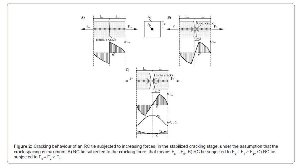
An RC tie is considered in the crack formation stage or in the stabilized cracking stage [4,5]. A reference system is introduced along the member axis with origin located at the zero-slip section (Figure 2).
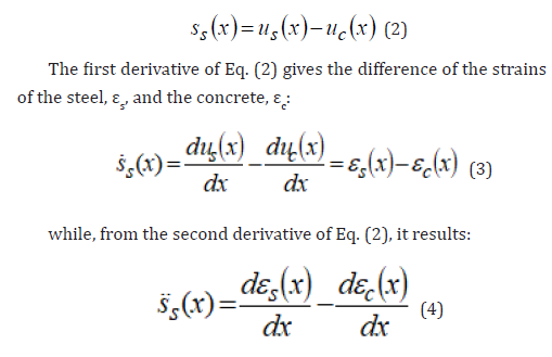
Along the transmission length, Ls, at a certain distance x from the zero-slip section, a slip between steel and concrete, ss(x), which represents the difference of the deformations of the steel, us(x), and the concrete, uc(x), occurs:
If one assumes a linear elastic behaviour for steel and concrete and considers the equilibrium of forces that act on infinitesimal blocks made of only steel or only concrete extrapolated from the RC tie, the two terms of Eq. (4) can be written in the following forms:
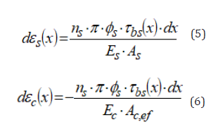
Therefore, the second order differential equation of the slipping contact between steel and concrete can be obtained, which is valid both in the crack formation stage and in the stabilized cracking stage:

For the crack formation stage, the solution of the differential equation (7) was obtained by Balázs in closed form [6], adopting the fib bond law (see Eq. (1)). On the basis of the Balázs’ solution the average bond stress, τbs,m, along the transmission length can be calculated from the equilibrium condition:
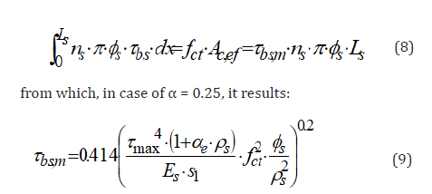
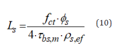
As an alternative to Eq. (9), for concretes of characteristic compressive strength, fck, between 30 MPa and 50 MPa, it can be referred to the tabular values of Table 1, that gives the values of the average bond stress-to-mean tensile strength ratio, τbs,m/fct, obtained from Eq. (9), as a function of the concrete strength, the reinforcement ratio and the bar diameter. In this way, from Eq. (8), the transmission length can be determined as:
Table:Values of the average bond stress-to-mean tensile strength ratio, τbs,m/fct

In the stabilized cracking stage, it is assumed that the maximum crack spacing remains unchanged and equal to twice the transmission length. The average bond stress remains also unchanged, as it must still transmit, from the zero slip section to the cracked section, an unchanged force acting on the concrete, that means Ac,ef · fct. The differential equation (7) is still valid, but the distribution of the bond stress cannot be expressed as a function of the slips along the whole transmission length without being in contrast with the equilibrium condition [4,5]. In effects, the fib bond law was obtained from an extensive experimental campaign based on pull-out tests in which secondary cracks cannot occur owing to the presence of concrete compressive stresses. It is, therefore, necessary to divide the transmission length into two zones (Figures 2B & 2C). The zone close to the zero-slip section is not affected by secondary cracks and, therefore, the fib bond law can be applied. In this zone, starting from the zero-slip section, the bond stresses tend to increase reaching a maximum value. On the contrary, the zone close to the cracked section is influenced by secondary cracks and the bond stresses tend to decrease becoming null at the crack. Moreover, differently from the crack formation stage, in the stabilized cracking stage the differential equation (7) cannot be solved in closed form, but an iterative numerical procedure is needed. Unknown of the mathematical problem is the length of the zone influenced by secondary cracks, named, according to Leonhardt [7], as reduced bond length, . This length is determined in such a way to obtain a null concrete stress at the cracked section. Finally, in the stabilized cracking stage the maximum crack width can be determined as difference of the elongations of the steel and the concrete along the maximum crack spacing:

Simplified Calculation Method
The general method is quite complex and is certainly not suitable for design purposes. Therefore, some simplifications are introduced here. Eq. (11) can be written with reference to the average values of the steel and concrete strains, εsm and εcm, respectively, along the transmission length, Ls:

In Eq. (12) the average strains of steel and concrete can be
determined from the local strains. In effects, the steel strain varies
from the value  at the cracked section to the value
 at the zero-slip section, while the
concrete strain is null at the cracked section and equal to
at the zero-slip section. Therefore, approximating the distributions of the steel and concrete strains (Figure 2C) with linear laws it results:
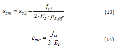
In order to take into account the effect of shrinkage of concrete, the concrete strain due to shrinkage, εc,sh, can be considered, leading to the following formula for the calculation of the maximum crack width:

Finally, the reference value of the maximum crack width is determined at the concrete surface of the structural member, not at the reinforcement level. For this reason, it is necessary to take into account the effect of the concrete cover, c. To this regard, as shown in Figures 2A, 2B & 2C, passing from the reinforcement level to the concrete surface, the crack width tends to widen. And this tendency increases with the increase of the steel stress. It results an increase of the maximum crack width dependent on concrete cover:

where β can be determined experimentally and assumed equal from 0.002 to 0.004, while σsr2 is the steel stress at cracked section under the cracking force. In conclusion, on the basis of Eq.s (15),(9),(13),(14),(16) the maximum crack width can be determined with the following formula:

Conclusion
The calculation of the maximum crack width is usually referred to the tension chord and the effective area of concrete. Taking into account the constitutive laws of materials and the main physical aspects, in particular those relating to cracking, a mathematical general method has been set up which allows the cracking behaviour to be analysed. However, the general method presents some calculation difficulties that are not suitable for design purposes. A simplified calculation method is, therefore, proposed which allows the main aspects of structural behaviour to be taken into account. In service conditions, the maximum crack width represents the reference value to be compared with the limits required by standards or contracts.
Acknowledgement
To God.
Conflicts of Interest
No conflict of interest.
References
- Ernst, Sohn (2013) fib International Federation for Structural Concrete. fib Model Code for Concrete Structures 2010. Berlin, p.434.
- (2004) CEN. EN 1992-1-1. Eurocode 2: Design of Concrete Structures-Part 1-1: General Rules and Rules for Buildings. European Committee for Standardization, Brussels, Belgium, p.225.
- Goto Y (1971) Cracks Formed in Concrete around Deformed Tension Bars. ACI Journal 68: 244-251.
- Debernardi PG, Guiglia M, Taliano M (2013) Effect of Secondary Cracks for Cracking Analysis of Reinforced Concrete Tie. ACI Materials Journal 110: 209-216.
- Debernardi PG, Taliano M (2016) An improvement of the Eurocode 2 and fib Model Code 2010 methods for the calculation of crack width in rc structures. Structural Concrete 17: 365–376.
- Balázs GL (1993) Cracking Analysis Based on Slip and Bond Stresses. ACI Materials Journal 90: 340-348.
- Leonhardt F (1988) Cracks and Crack Control in Concrete Structures. PCI Journal 33: 124-145.
-
Pier Giorgio Debernardi, Maurizio Taliano. Fundamentals for Cracking Verification of Reinforced Concrete Structures. Cur Trends Civil & Struct Eng. 7(1): 2021. CTCSE.MS.ID.000654.
-
Reinforced concrete, Cracking, Construction, Structural members, Tensile strength, Bond stress, Transmission, Crack width
-

This work is licensed under a Creative Commons Attribution-NonCommercial 4.0 International License.


