 Research Article
Experience of Using Drilling Injection EDT Piles in Emergency Response of a Public Building
Sokolov NS, Chuvash State University, Russia.
Received Date: April 19, 2021; Published Date: May 21, 2021
Abstract
The case of ill-considered construction of a two-Storey brick building in the zone of geotechnical influence of the operated building which resulted in its emergency condition was considered. Timely accident prevention measures, including reinforcement of the foundation by means of drilled injection EDT piles and safety measures, such as arrangement of prestressed ties from eight rows of high-strength valves enclosing a supporting wall of two rows of drilling injection EDT piles of Ø350 mm, made by electric-discharge technology from the side of the altar, allowed to save the monument of federal architecture from collapse.
Keywords: Strain cracks; Strain rate; Drilling injection pile; Electro-discharge technology; Emergency response commission
Introduction
Any proposed construction in a geotechnical zone requires special consideration both at the decision-making and at the construction stage. All possible construction risks should be analyzed. This article illustrates the example of disregard of the laws of soil mechanics, geotechnics, and technology of construction of buildings and structures, which resulted in an emergency situation. For example, in April 2004, vertical cracks of a deformative character appeared on the outer walls of the building of the Vvedenskij Cathedral in Cheboksary (Figure 1). The first defects appeared at the attic level on the walls of the northern and southern parts of the Cathedral, so the building of the temple split into two parts. The cracking speed reached 10.0-15.0mm/day. An emergency was created, leading to a possible collapse. The emergency commission established quickly stated that the cause of the cathedral’s emergency deformations was the impact of the construction of the building of the residence of His Grace of the Cheboksarskaya and Chuvash Eparchy from the altar at a close distance from the temple. The construction of a two- Storey brick building on the tape foundations with prefabricated hollow-core floor slab panels in the autumn of 2003.In April 2004, it had only foundations without a basement floor cover, i.e. its foundation was frozen throughout the winter period 2003-2004. Thus, the deformation of the Cathedral began just during the period of thawing of the base [1-14] (Figure 1).
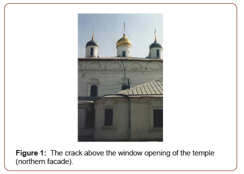
The commission suggested that the Cathedral building was most likely set in motion by the process of extrusion of soils from under the basement of the foundations.
Research Methods
The following activities were organized rapidly: Geotechnical monitoring of fracture development (Figure 2), inspection of the technical condition of the emergency building for the purpose of identification of residual load capacity, and geotechnical exploration (Figure 2).
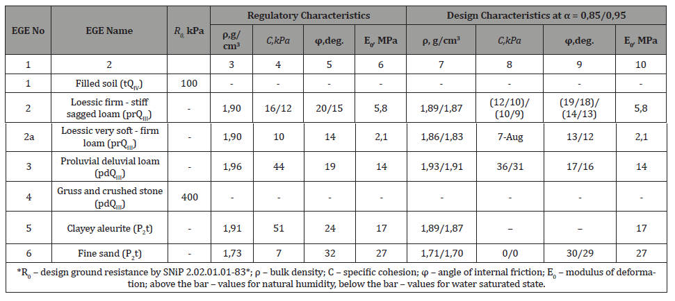
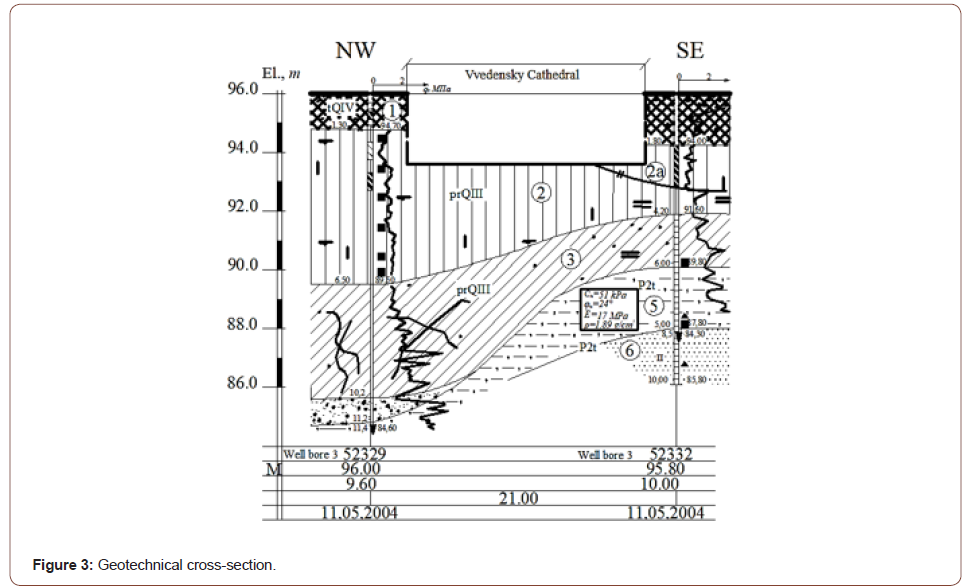
The building of the Vvedenskij Cathedral (1651) is a brick building with a plan of 37.4×35.3m (Figure 1). It consists of the main part: temple 13.0 m high with apsis up to 4.5 m high, three chapels with apsises. The height of the chapels is 4.2-4.5m. Apsises are semicircle-shaped edges covered with a vault and oriented to the east. The foundations of the Cathedral are shallow with dimension stone footing on a lime solution. Depth is 2.0-2.4m. One of the points of implementation of the emergency measures was the development of a working construction documents of strengthening the foundations. According to the results of engineering-geological surveys carried out in 2004 the following engineering geological elements (EGE) are located on the territory of the Vvedenskij Cathedral: EGE 1 is a fill-up soil (tQIV) that falls to a depth of 0.8-1.8m. Widely spread around the building beyond the foundation of the foundation; EGE 2-a loess soil (prQIII) with permeable properties at full depth, mainly hard plastic consistency (with a plasticity index Ir=9%). It is distributed throughout the entire area to a depth of 4.0-6.5m. Its relative permeability εsl varies from 0.01 to 0.032 when soaked at 0.2 MPa load, and the initial seepage pressure, Psl, varies from 0.055 to 0.2 MPa. The type of ground conditions by permeation is the first; IGE 2a-very soft-firm loess soil (prQIII) generally non-seedling (αsl=0.0072), maintaining a low mileage subtle property in rare small amounts of soil. Predominantly in the eastern part of the site; EGE 3-proluvial diluvial soothworm (pdQIII) from semi-hardness to tugoplastic consistency, in the eastern part-soft-plastic consistency. It is lagging everywhere, increasing in capacity to 4.5m in the northern part of the site; EGE 4-gowns and crushed stone (pdQIII) with sandsuglinite placeholder; EGE 5-clayey Aleurites (P2t). It is open in the south. It has a capacity of about 1.0m; EGE 6-fine sand (P2t) with small sand layers. Table 1 shows the physio-mechanical characteristics of the soils making up the study site, and Figure 3 shows the geotechnical cross-section. (Table 1).
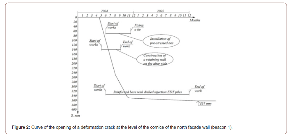
Table:Physico-mechanical characteristics of soils.
Results and Discussion
An analysis of the results of the geotechnical surveys suggests degradation of the physical and mechanical properties of the foundation soils. Particular attention should be paid to the low value of the modulus of deformation E0=2.1 MPa for layer 2a-the very soft-firm loess loam soil (PrQIII). The decision of the Emergency Committee to develop emergency measures instructed the NPF “FORST” to develop a project to strengthen the foundations of the Cathedral building, including the chapels and altar. Two types of drilling injection piles were considered: these are piles made without compacting the sides of the well, and piles with compaction of the soil of the sides of the well–EDT piles. The determining factor in deciding on the type of drilling injection pile was its bearing capacity. Thus, the soil bearing capacity of the EDT pile exceeds by approximately 65% the load capacity of the drilling injection pile without wellbore seal. It is known that the following algorithm is used for reconstruction or, if necessary, for construction of a drilling injection pile due to insufficient bearing capacity of the base:
1) satisfaction of PIImt ≤ R condition, where PIImt is an average pressure under basement base is checked; R (SP 50-102- 2003 “Design and construction of pile foundations”) is a design resistance of the bearing layer of the foundation;
2) if the condition in paragraph 1 is not met, the external center of gravity load of the foundation footing required for transfer to the drilling injection piles: N=Pextra*A=((PIImt-R))/R*A (where A is the soles area for the pier foundations A=l*b, and for the continuous foundation A=b*1).
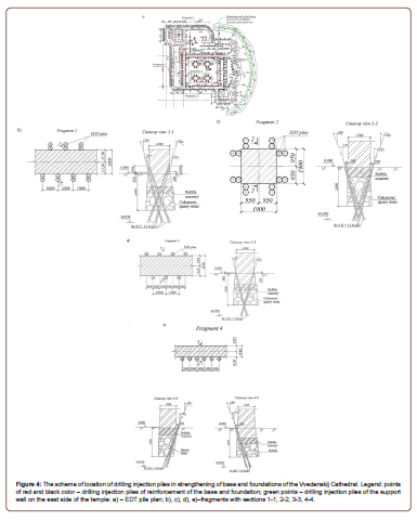
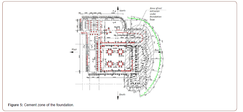
During the construction of drilling injection EDT piles [5] along the wall of the iconostasis excess normative expenses of finegrained concrete were found. For example, with a pile geometric volume of ≈ 0.3 m3 the consumption of concrete reached 5.0 m3. Notice the non-decreasing levels in pre-treatment concrete filled wells. Electrohydraulic treatment at the level of the foundation footing revealed a sharp drop in levels, which confirms the presence of voids under the base, thereby filling the voids with fine-grained concrete. As a result of the drilling injection EDT piles construction the foundations of the iconostasis and altar walls were cemented simultaneously (Figure 5). Simultaneously (again from the premise of squeezing the ground from underneath the base of foundations) the project of fencing the ground of two rows of drilling injection piles with the diameter Ø350.0 mm with a step of 0.5 m between with the construction of a band belt on top of the piles (Figure 4A) and the building was reinforced with pre-tense tenders of eight rows at the level of the carnival (Figure 5).
Conclusion
1. The considered emergency situation arose as a result of the construction of the building of the residence of his Grace of the Cheboksarskaya and Chuvash Eparchy in the zone of geotechnical influence, as a result of this in April 2004 on the outer surfaces of the walls of the building of the Vvedenskij Cathedral in Cheboksary appeared vertical cracks of a deformative character. Defects at the level of attic surfaces and defects developed further on the northern and southern facades split the building in two parts in the direction west east. Thus, the threat of collapse of the building of the Ivana Cathedral has arisen.
2. The speed of cracks development has been established in the range of 10-15mm/day. An emergency commission established urgently to develop emergency measures to save the monument of history and culture of federal importance has established that the cause of deformation of the Cathedral was the effect of the construction of the building of the residence of His Grace of the Cheboksarskaya and Chuvash Eparchy near the temple. The following works were done urgently:
a. engineering and geological surveys;
Based on the above the number of piles without compaction is 1.6 times larger than drilling injection EDT piles. Considering that the cost per meter of the above-mentioned piles does not differ much from each other the cost of works for strengthening the foundation would increase by 1.6 times. Thus, the EDT drilling injection pile 11.0m long (taking into account the sealing into bedrock soils and passage of a foundation depth of 2.5m Ø180mm by core drilling) is accepted as the reinforcement option. The number of piles within the Cathedral area is different, for example: there are two piles per meter under apsis; four piles per meter under the temple walls; there are 16 piles under the walls of vaults. In total more than 800 drilling injection EDT piles are designed (Figure 4). The hypothesis proposed by the authors that the deformation of the Cathedral was occurred as a result of forcing the soil out from under the foundation footing was confirmed in the process of works on strengthening the foundation. It was fair for the plot of the Cathedral from the iconostasis wall to the altar (Figure 3) (in the direction of the building of his Grace of the Cheboksarskaya and Chuvash Eparchy). The probability of extrusion was high due to the presence of a soft-fluid-plastic consistency loam with a module of general deformation E0=2.1 MPa under the base of the Cathedral foundations. (Figure 4)
b. the technical condition of the Cathedral building was examined;
c. emergency measures have been developed, including strengthening the foundations, strengthening the building with the help of pre-tense tenders from eight rows of high-strength screw valves on the outer perimeter at the level of carnival. As a result of the engineering and geological surveys and the technical survey the presence of cavities under the soles of the eastern parts of the building (wall with the tsarist gates, walls of the altar) was revealed.
3. The implementation of the developed emergency measures has prevented a pre-emergency situation. When the maximum cracks of 357 mm were reached, the deformation of the Cathedral has been stopped. The Cathedral is still in operation without failure.
Acknowledgment
None.
Conflict of Interest
No conflict of interest.
References
- Korff M, Meijers P, Wiersma A, Kloosterman F (2019) Mapping liquefaction based on CPT data for induced seismicity in Groningen. Earthquake Geotechnical Engineering for Protection and Development of Environment and Constructions-Proceedings of the 7th International Conference on Earthquake Geotechnical Engineering. pp. 3418-3425.
- Deckner F, Viking K, Guillemet C, Hintze S (2015) Instrumentation system for ground vibration analysis during sheet pile driving. Geotechnical Testing Journal 38(6): 893-905.
- Brinker RBJ (2006) Plaxis: Finite Element Code for Soil and Rock Analyses. Balkema pp. 53-56.
- Denies N, Holeyman A (2017) Shear strength degradation of vibrated dry sand. Soil Dynamics and Earthquake Engineering 95: 106-117.
- Karol Reuben H (2003) Chemical grouting and soil stabilization. American Society of Civil Engineers P. 536.
- Moseley MP (2004) Ground improvement. London P. 440.
- Ilichev VA, Mangushev RA, Nikiforova NS (2012) Underground exploration experience. Experience of Development of Russian Megacities Underground Space. Soil Mechanics and Foundation Engineering (2): 17-20.
- Ulickij VM, Shashkin AG, Shashkin KG (2010) Geotechnical Support of Urban Development. St. Petersburg Georeconstruction Publ P. 551.
- Ter-Martirosyan ZG (2009) Soil mechanics, P. 550.
- Ukhov SB (2007) Soil mechanics and foundations P. 561.
- Ulitsky VM, Shashkin AG, Shashkin KG (2012) Geotechnical Guide (guide to bases, foundations and underground structures). SPb P.284.
- Sokolov NS, Sokolov SN (2005) The use of drilling injection piles when fixing slopes. Materials of the fifth all-Russian conference on New in architecture, design construction renovation (NADCR-2005). Cheboksary: Publishing house of the Chuvash University, pp. 292-293.
- Sokolov NS (2014) Method for calculating the bearing capacity of drilling injection piles taking into account the «foot bearings». Materials of the 8th All-Russian (the 2nd International) conference on New in architecture, designing construction and renovation» (NADCR-2014). Cheboksary: Publishing house of the Chuvash State University. pp. 407-411.
- Sokolov NS, Ryabinov VM (2015) About one method of calculating the bearing capacity of drilling injection EDT piles. Soil Mechanics and Foundation Engineering 1: 10-13.
-
Sokolov NS. Experience of Using Drilling Injection EDT Piles in Emergency Response of a Public Building. Cur Trends Civil & Struct Eng. 7(3): 2021. CTCSE.MS.ID.000663.
-
Strain cracks, Strain rate, Drilling injection pile, Electro-discharge technology, Emergency response commission, Construction, Building
-

This work is licensed under a Creative Commons Attribution-NonCommercial 4.0 International License.


