 Short Communication
Effects of Vertical Component of Earthquakes on Cable-Stayed Bridges
Behnam Babaei Ravandi and Shervin Maleki*
1Postgraduate student, School of Civil & Environmental Engineering, Addis Ababa Institute of Technology Addis Ababa University, Ethiopia
2Associate Professor of Structural Engineering, Addis Ababa Institute of Technology Addis Ababa University, Ethiopia
Amanuel Tesfaye, Postgraduate student, School of Civil & Environmental Engineering, Addis Ababa Institute of Technology Addis Ababa University, Ethiopia.
Received Date: November 02, 2021; Published Date: January 14, 2021
Abstract
The vertical component of ground motions is known to cause severe damages to certain structures. Long span cable-stayed bridges are among those vulnerable structures due to their high mass and cables that take no compression. In this paper, the vertical earthquake effects on several cable-stayed bridges have been investigated using 3-D nonlinear time history finite element analyses. Different main span lengths, pylon shapes and pylon/deck connection types are considered. The results indicates that the vertical ground motion component should be considered in the analysis of such bridges and affects many key elements of the bridge.
Introduction
The first cable stayed bridge was built in the mid twentieth
century. Since then, the construction of cable-stayed bridges has
spread rapidly and nowadays this type of bridge is one of the most
used bridge types for long span lengths. Cable-stayed bridges are
popular both from structural aspects and aesthetic point of view.
Seismic evaluation of bridges has been the subject of research
for many years. However, the effect of vertical component of an
earthquake has been researched only for few types of bridges.
The vertical component of ground motions near an active fault has
been known to be high and have caused severe damages to certain
structures vulnerable to vertical acceleration. Long span bridges
like cable-stayed bridges are very massive and are only supported
on the pylons. These structures can be vulnerable to vertical
acceleration even when they are built away from active faults.
There is a need for such an investigation into the behavior of cablestayed
bridges subjected to vertical ground motion simultaneously
with horizontal ground motions.
To the best knowledge of the authors, the effects of vertical
component of an earthquake on cable-stayed bridges in the form
presented here has not been investigated before. To achieve an
accurate estimate of the vertical component effects, different main
span lengths, pylon shapes and pylon/deck connection types
were considered. The results of 3-D nonlinear time history finite
element analyses of such cable-stayed bridges subjected to three
components of earthquakes were compared with analyses under
only horizontal components. The results indicated that the vertical
ground motion component should be considered in the analysis of
cable-stayed bridges and greatly affects the deck and pylon internal
forces.
Literature Review
The first complete analytical study into the effect of
vertical ground motions on ordinary bridges was conducted by
Saadeghvaziri & Foutch [1]. They used a finite element code capable
of modeling the inelastic behavior of reinforced concrete columns
under combined horizontal and vertical deformations. With threedimensional
finite-element models of eight bridges, they showed
that the vertical acceleration causes varying axial forces in the piers
and a pinched hysteresis loop in the columns.
Yu et al. [2] showed that vertical accelerations could significantly
increase the tensile stresses in the deck and in axial forces (about 20%) while only a marginal change in the longitudinal moment
was observed. Button et al. [3] worked on parametric studies of
the vertical ground motion effect, including ground motion and
structural characteristic of bridges. Gloyd [4] studied values for
vertical deck shear and bending moment for two continuous span
bridges and showed that the dynamic response from vertical
acceleration can be much larger than the dead load effects and a
reversal of flexure in the deck can occur in both positive and negative
moment areas. Elnashai & Papazoglou [5] and Collier & Elnashai
[6] focused on near-fault ground motion studies. They proposed
that the damping ratios for elements which are susceptible to
vertical excitation should be limited to 2%. They concluded that the
moments and axial forces in piers fluctuate from null up to twice
the dead load; moreover, they asserted that heavier decks intensify
the vertical effects of ground motions.
More recently, Veletzos et al. [7] investigated the effect of
vertical compound of ground motion on the seismic response of
precast segmental concrete bridges. They found 400% increase in
bending rotations due to vertical ground motion.
Abdel-Ghaffar & Nazmy [8] investigated nonlinear seismic
behavior of cable-stayed bridges. They showed that for long span
cable-stayed bridges nonlinear dynamic analysis is a necessity.
Shrestha [9] considered responses of cable-stayed bridges
subjected to earthquakes with and without vertical ground motion
using near fault ground motions.
Bridge Characteristics
In this study, the most typical features of commonly constructed
cable-stayed bridges were identified and used in the numerical
studies of this research. More than 45 cable-stayed bridges were
categorized based on parameters like span length, pylon shape,
deck to pylon connection type. The main features of the finite
element (FE) models were as follows.
Span lengths
Investigation shows that most of the cable-stayed bridges constructed and in use have more than two spans. As a result, all the bridges analyzed in this study had three spans with two pylons. The variation in middle span length for cable-stayed bridges analyzed were chosen to be 300 meters, 400 meters and 500 meters long. The lengths of the side-spans, pylon height and the number of stay cables were determined based on a commonly used (rule-ofthumb) fraction of the main span length. The side-span lengths were considered as 40% of the main span length. The height from the deck to top of the pylons were considered as 30% of the main span length. In addition, the clear height of the pylon below the deck was assumed to be 50 meters for all models.
Cables
Cables were arranged as semi-fan for all bridges. The horizontal distances between cables’ attachment points to the deck were 10 meters for the main and 8 meters for the side spans.
Pylon shapes
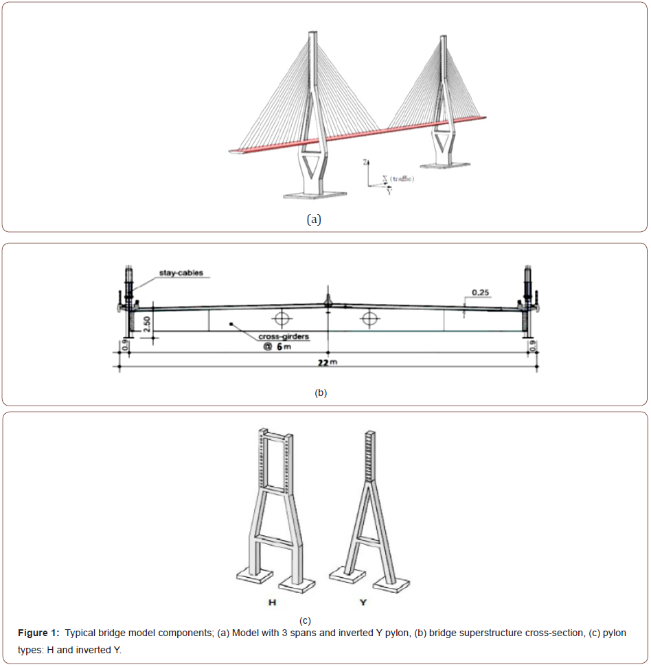
‘H’ and ‘inverted Y’ pylon shapes were chosen since they are mostly used shapes and typically preferred by designers (see Figure 1).
Deck-Pylon connection
Two types of connection were selected for this study. In the first
type, the deck was connected only in the horizontal directions to
the pylon and the weight of the bridge was supported by cables.
In the second type, the deck was connected to the pylons in the
vertical and transverse directions with an elastomeric bearing and
the longitudinal direction was released. Both connections restricted
rotations of the deck in the longitudinal direction.
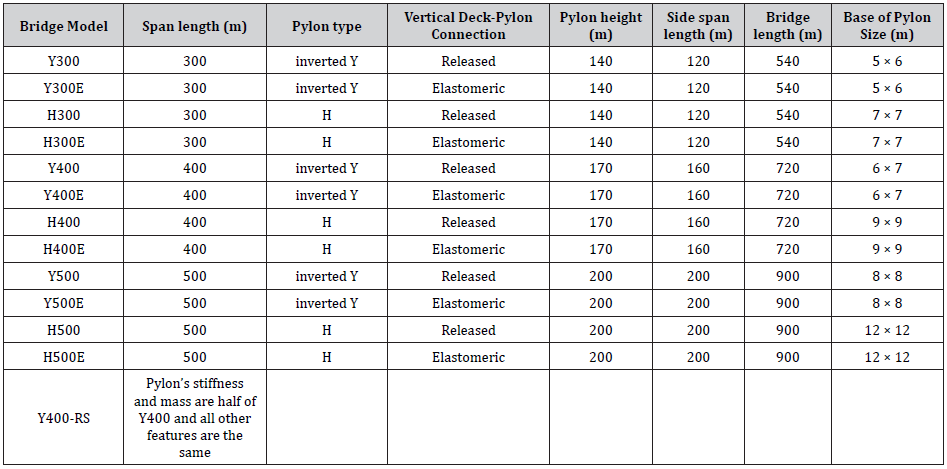
Table 1 provides a convenient summary of the geometric
characteristic of all bridge models. According to Table 1, there are
12 main models for parametric study. Moreover, there is another
model in which the pylons stiffness and mass are reduced by 50%
to determine the effect of changing the stiffness of pylons on cablestayed
bridges responses. Table 2 provides some key vertical and
horizontal dynamic characteristic of the bridge models.
Table 1: Bridge models geometric characteristics.
Finite Element Models
All models were developed and analyzed using the CsiBridge
software [10]. Decks consist of two main girders on each side and
cross-girders connecting the two main girders at 6 m spacing. Width
of the deck was 22 meters (see Figure 1). These girders were not
modeled directly, instead a single frame element with equivalent
stiffness was used for each span.
The decks in side-spans were heavier than the decks in main
span, because a zero deflection under dead load was desired
throughout the spans. The cables were prestressed in all models
to obtain a straight horizontal deck after deformation of the
bridge under the dead load. The 61 wire steel strand cables had
an ultimate strength of 1740 MPa and yield strength of 1200 MPa.
The structural steel used had a yield strength of 360 MPa. All pylon
bases were considered as fixed. Connections between abutments at the ends of the bridge and the deck were restricted in the transverse
and vertical directions and for torsional rotation.
Ground Motions for Time History Analyses
A suite of four-time history records, each consisting of two horizontal and one vertical component, were considered. The suite consisted of Imperial Valley (El Centro station), Tabas (Dayhook station), Northridge (Sylmar station), Loma Prieta (Corralitos station) and San Fernando (Pacoima dam station) records. The bridges were analyzed four times for each time history record. The first analysis used all three components of the record in which the strong horizontal component of earthquake was applied along the longitudinal direction. The second analysis was like the first one, but the vertical component of the earthquake was eliminated. For the third analysis, the direction of the strong horizontal component was changed to be in the transverse direction of the bridge. In the last analysis, the vertical component was eliminated from the previous analysis. Both horizontal components of time history records were scaled to the AASHTO [11] design code spectrum shown in Figure 2. The nonlinear time history analyses using direct integration scheme were started after applying the dead loads on the structure. The two first main horizontal modes damping ratio was assumed as 2% and the Rayleigh damping modal matrix was formed by the program in accordance with mass and stiffness proportional damping rules.

Analyses Results
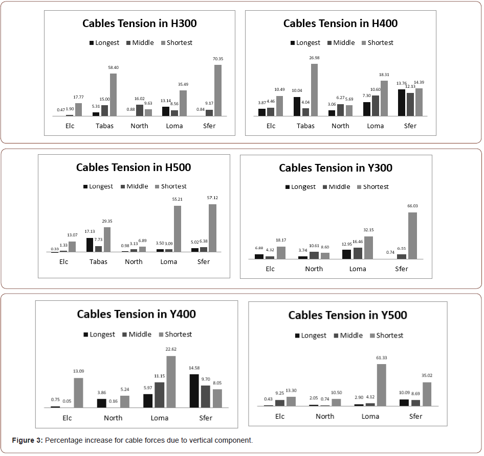
The effect of vertical component of earthquake on cable-stayed bridges was examined by comparing the difference in response of the bridge components resulting from three-components (3C) and two-components (2C) time history analyses This comparison was evaluated as (3C-2C)/2C ratio which gives the percent difference of the internal force when vertical component is considered.
Cable Forces
The values for this ratio are plotted in Figure 3 for the longest, middle, and shortest stay cables of bridge models for the considered earthquake records. The shortest cables are near the pylons and are affected the most by the vertical component of the earthquake records. The figure shows the trend of decreasing ratio as the length of cables increase. This trend is repeating in all bridges and earthquake records except in Northridge record in main span length of 300 meters and San Fernando record in main span length of 400 meters. These exceptions are related to frequency content of records and dynamic characteristic of bridges. These figures show that great errors can occur in analysis when the vertical component of the earthquake is ignored. For example, the cable tension ratio for San Fernando record for H300 model is as high as 70%. This means a 70% higher tension force is expected when the vertical component is considered in the analysis of this bridge. The results from Loma and San Fernando are intensified because of the vertical frequency content of these records which was close to the vertical periods of bridges.
Deck Forces
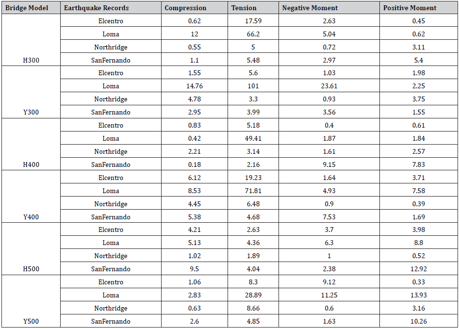
In Table 3 the percentage increase for the deck forces and moments are displayed for selected bridges when vertical component is considered. The most significant force which is influenced by the vertical ground motion is the axial tension at midspan of the deck. This force fluctuates up to 101% if the vertical ground motion is considered (Loma earthquake in Y300). The maximum compression force in the deck is located near the pylons and it seems that it is not very sensitive to the vertical component of earthquakes. The maximum positive moment in the deck occurred near the midspan and the (3C-2C)/2C ratios for this moment went up to 14% (Loma Y500). The maximum negative moments in the deck were not as significant as positive moments. However, in a special case (Loma Y300) it was increased to 23.61%.
Table 2: Bridge models dynamic characteristics.

Table 3: Percentage increase for the deck forces.
Other Forces
In addition, some other internal forces and displacements were monitored to examine the error resulting from eliminating the vertical component of ground motions. These were deck weak axis moment, deck torsion, deck transverse shear and horizontal displacements of pylons top. These features were not affected significantly (below 15%) by the vertical component and are not shown for brevity.
Table 4: Percentage increase in pylon forces.
Pylon Forces
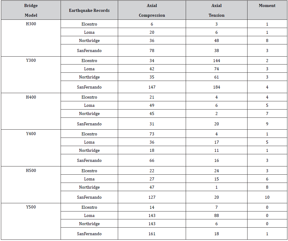
Table 4 shows the (3C-2C)/2C ratio at the base of pylons. As the table indicate the moment in the pylons were not sensitive to the vertical earthquake components and the ratios for moments were below 10%. The crucial forces in pylons were tension and compression axial forces. The increase in these forces depend on bridge span and frequency content of earthquakes, but as a rule of thumb, as the main span of bridges was increased the ratios increased. In addition, the inverted Y pylon could be influenced more significantly by the effect of vertical component of earthquakes than bridges with H pylon.
Table 5: Percentage increase of forces for deck due to deck-pylon connection.

Effect of deck-pylon connection
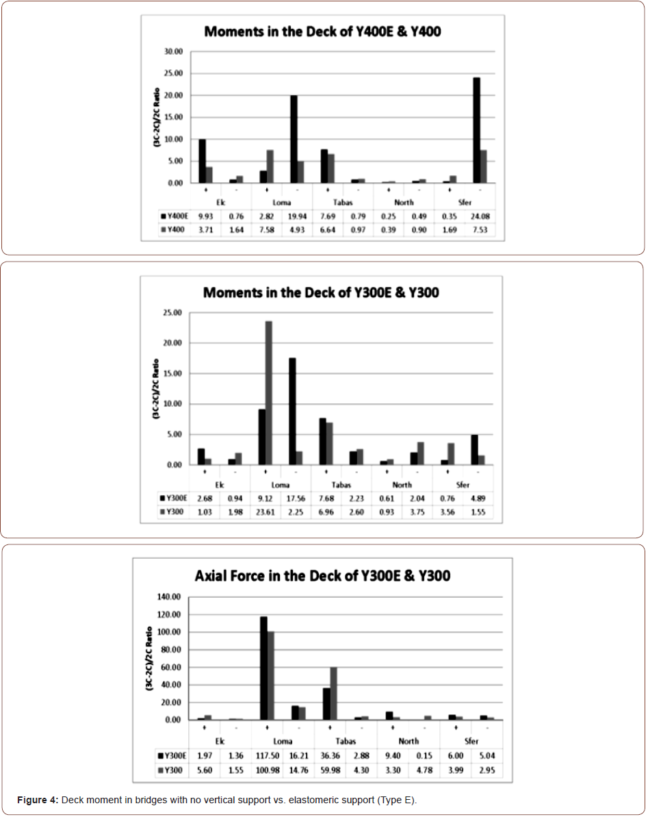
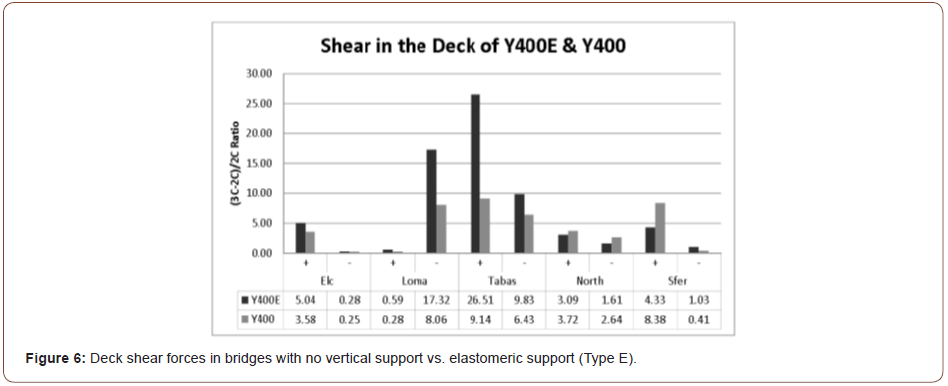
As mentioned previously, bridges were analyzed for two types of deck-pylon connection. In the first type the vertical support at pylon was eliminated and the bridge was hanging from the cables. In the second type (Type E), an elastomeric bearing was provided at the deck/pylon connection. Overall, the first type was more sensitive to vertical component of the earthquake. The effect of this parameter on the positive and negative moments in the deck is illustrated in Figure 4. A maximum of 24% increase in moments can occur when vertical component is considered in the analyses. Figure 5 shows the worst increase in axial deck forces which is as high as 118%. Figure 6 shows the worst increase in deck shear forces which is as high as 26.5%.

In another model, the effect of eliminating the longitudinal connection of deck-pylon was investigated. The results as shown in Table 5 shows that, the (3C-2C)/2C ratios in cables increased when the decks were not connected to pylons longitudinally. In addition, the ratios for deck forces were increased. Moreover, the forces in pylons were decreased.
Effect of Pylons Stiffness
The stiffness used in analyses of bridges was calculated by the
program. To examine the sensitivity of vertical response to this
parameter, time history analyses were performed on Y400 bridge
using moment of inertia and cross-sectional area and masses
that were halved. This model is called Y400-RS. The dynamic
characteristic of the bridge was not changed significantly, for the
mass and the stiffness of the pylons change simultaneously and the
period of the whole structure was almost the same. Table 6 shows
the level of forces in both bridges. The level of forces in reduced
stiffness bridge is decreased significant; as a result, the designing of
the pylons could be very important in forces in deck.
The (3C-2C)/2C ratios in both of bridges for San Fernando
earthquake are shown in Table 6. As the table shows, the ratio in RS
bridge is higher especially, in maximum tension forces of the deck.
However, the (3C-2C)/2C ratios for cable forces were the opposite.
Also, displacement in the middle of the deck increased significantly
as the stiffness of the pylons was reduced.
Table 6: Percentage increase of pylon forces due to reduced stiffness.

Effect of pylon type
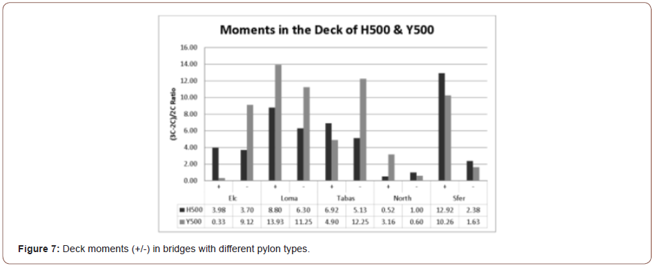
Vertical component of earthquakes affected the bridges in both pylon types. In the deck, the inverted Y pylons generate greater difference in forces than H pylons when vertical component was considered. In addition, the inverted Y pylons were affected more significantly in axial tension and compression forces in the pylons. Figure 7 shows a maximum of 14% increase in Y-500 in comparison to H-500 bridge models.
Conclusion
Bridge design codes like AASHTO have not provided specific vertical response spectra for the design of bridges. This research, by using extensive nonlinear time history analyses on selected bridges, showed that the effect of vertical component of earthquakes on the cable-stayed bridges considered can be very significant in some cases.
The conclusions for this study are as follows:
1. The impact of vertical ground motion is significant and cannot be ignored.
2. The cable forces near the pylons showed a maximum increase of 70% when the vertical component of earthquake was considered.
3. The axial tension at the midspan of the deck showed a maximum increase of 100% when the vertical component of earthquake was considered.
4. The deck weak axis moment, deck torsion, deck transverse shear and horizontal displacements of pylons were not affected significantly when the vertical component of earthquake was considered.
5. The inverted Y pylons were affected more by the vertical
earthquake than the H pylon cable-stayed bridges.
6. Having a vertical support at the deck-pylon connection
was better than not having a vertical support.
7. As the pylons stiffness and mass were decreased by 50%,
the level of deck forces was increased significantly.
8. The responses showed that releasing the longitudinal
restraint at the deck/pylon connection increased the cable
forces and deck forces. However, the forces in pylons were
decreased.
Acknowledgement
None.
Conflict of Interest
No conflict of interest.
References
- Saadeghvaziri MA, Foutch DA (1991) Dynamic behavior of R/C highway bridges under the combined effect of vertical and horizontal earthquake motions. Earthquake Engineering and Structural Dynamics 20: 535-549.
- Yu CP, Broekhuizen DS, Roesset JM, Breen JE, Kreger ME (1997) Effect of vertical ground motion on bridge deck response. Proc., Workshop on Earthquake Engineering Frontiers in Transportation Facilities, Tech. Rep. No. NCEER-97-0005, National Center for Earthquake Engineering Research, State Univ of New York at Buffalo, N.Y: 249-263.
- Button MR, Cronin CJ, Mayes RL (2002) Effect of Vertical Motion on Seismic Response of Highway Bridges. ASCE Journal of Structural Engineering 128: 1551-1564.
- Gloyd S (1997) Design of ordinary bridges for vertical seismic acceleration. Proc., FHWA/NCEER Workshop on the National Representation of Seismic Ground Motion for New and Existing Highway Facilities, Tech. Rep. No. NCEER-97-0010, National Center for Earthquake Engineering Research, State Univ of New York at Buffalo, N.Y: 277-290.
- Elnashai AS, Papazoglou AJ (1997) Procedure and spectra for analysis of RC structures subjected to strong vertical earthquake loads. J Earthquake Eng 1(1): 121-155.
- Collier CJ, Elnashai AS (2001) A Procedure for Combining Vertical and Horizontal Seismic Action Effects. Journal of Earthquake Engineering 5(4): 521-539.
- Veletzos MJ, Restrepo JI, Seible F (2006) Seismic response of precast segmental bridge superstructures. Cal Trans Tech. Report UCSD/SSRP-06/18.
- Abdel Ghaffar AM, Nazmy A (1991) Nonlinear Seismic Behavior of Cable-Stayed Bridges. Journal of Structural Engineering 117(11).
- Shrestha B (2015) Seismic response of long span cable-stayed bridge to near-fault vertical ground motions. KSCE Journal of Civil Engineering 19: 180-187.
- AASHTO (2020) LRFD bridge design specifications (9th ed.). The American Association of State Highway and Transportation Officials.
- CsiBridge, version 20, Computers & Structures, Inc. Structural and Earthquake Structural Software. California, USA.
-
Nader Zad, Hani Melhem. Response Modal Nonlinear Time-History Dynamic Analyses of the Northridge Earthquake of a Two-Storied Steel Structure with Rubber Isolator and Fixed-Base Systems. Cur Trends Civil & Struct Eng. 8(2): 2021. CTCSE. MS.ID.000685.
-
Earthquakes, CsiBridge software, Deck forces, Cables, Span lengths, Cable forces
-

This work is licensed under a Creative Commons Attribution-NonCommercial 4.0 International License.


