 Research Article
Crack Detection in Environments with Complex Backgrounds Using Deep Convolution Neural Nets
Mohamed Elmorsy*1,2, Hazem Elanwar1, Ahmed Elbanna3 and Sherif A Mourad1
1Department of Structural Engineering, Faculty of Engineering, Cairo University, Egypt
2Department of Civil Engineering, McMaster University, Canada
3Department of Civil and Environmental Engineering, University of Illinois at Urbana-Champaign, USA
Mohamed Elmorsy, Department of Civil Engineering, McMaster University, Canada.
Received Date: March 30, 2022; Published Date: April 05, 2022
Abstract
Structural health monitoring has become one of the most important fields of research in the engineering communities to mitigate the risk of human and economic losses due to structural damage or deterioration. In recent years, and with advancements in computational abilities, computer vision techniques have been used effectively for structural monitoring. The widespread of consumer-grade and smartphone cameras allows computer vision to be a superior data collection tool especially in large-scale events such as earthquakes. While, deep convolution neural networks are promising robust techniques in computer vision and machine learning, one of their challenges is acquiring a reliable and large enough dataset for training, which in turn affects the accuracy of the results significantly. In this paper, a deep convolution neural network for crack detection is developed and its robustness is assessed based on images in environments with complex backgrounds. A new approach in adopted to overcome the limited training dataset by creating synthetic cracked beams images using the extended finite element method. The proposed approach effectively increased training and validation accuracies and achieved an average testing accuracy of 98.2%. The network is combined with a reporting system that uses a sliding window technique to eliminate overall image size.
Keywords: Crack detection; Structural health monitoring; Deep convolution neural networks
Introduction
Civil structures are invariably designed to function robustly for a selected period of time, which is often referred to as the economic cycle of the structure. After exceeding this period of time, structures might be susceptible to deterioration that it is necessary to inspect those structures on regular basis. Also, civil structures which are subjected to dynamic and cycling loading experience fatigue stresses, leading to cracks and loss of local stiffness and material discontinuities [1]. Another major cause of structures deterioration is natural disasters; like earthquakes, tornadoes and floods, and post- disasters inspection of structures is a vital process for public safety. The conventional on-site inspection approaches of civil structures are time-consuming and human dependent. The results may be limited by the inspectors’ visual ability, knowledge, and might be subjective to personal perception. In addition, not all civil structure elements are accessible to inspectors especially after natural disasters. Accordingly, applying automated techniques such as computer vision can improve the assessment procedure significantly. For many years, the engineering research communities have been working on proposing structural health monitoring (SHM) techniques to prevent any unpredicted structural failure that can lead to loss of lives and major economic loss. Many of these proposed methods are local damage identification methods and they can be included in one of the following categories: visual or localized experimental methods such as ultrasonic or acoustic methods, magnetic field methods, radiography, thermal field methods or eddy-current methods [2]. Also, other global vibrationbased damage identification methods were presented and reviewed by Doebling, et al. [3]. More recent work on vibration-based damage identification using numerical methods are proposed by Rabinovich et al. [4]; Chatzi et al. [5]; Cha & Buyukozturk [6]; Teidj et al. [7]; Hou et al. [8].
Due to the fast-growing advancement in visual sensing technologies (e.g., digital cameras), consumer-grade and smartphones high quality cameras are becoming available at a lower cost than ever before, which have been proven effective for advanced structural health monitoring and dynamic applications [9]. This accelerated research work on Computer Vision (CV) methods for damage detection and identification, primarily using Image Processing Techniques (IPTs) (Abdel- Qader et al. [10]; Yamaguchi et al. [11]; Prasanna et al. [12]; Chen et al. [13]; Cha et al. [14]). Koch et al. [15] categorized several state-of-the-art computer vision methodologies which are used to automate the process of the defect and damage detection. These methods are primarily developed based on IPTs, such as edge and boundary detection, template matching, filtering, background subtraction, region growing, texture recognition and histogram transform. These techniques have been used, tested, and evaluated to identify different defect and damage patterns in concrete bridges and buildings, precast concrete tunnels, underground concrete pipes and asphalt pavements [15]. CV techniques to date detect different types of damage such as cracks, corrosion in steel and concrete, voids in steel and concrete, delamination, and loosed bolts [16]. Current existing crack detection and assessment algorithms for concrete bridges are classified as, edge detection, segmentation, percolation, machine learning (ML) methods, morphology operations, ground and aerial robot photography, template matching, among other techniques [17].
According to LeCun et al. [18], Machine Learning Algorithms (MLAs) have more practical adaptability, and, recently, many research groups have implemented MLAs-based classifications combined with IPT-based image feature extractions, however, the results are still affected by the false- feature extraction of IPTs [19-23]. Different types of Artificial Neural Networks (ANNs) have been developed and implemented in research and industrial fields. Convolution Neural Networks (CNNs) which are inspired by the visual cortex of animals [24], unlike the standard NNs can effectively capture the grid-like topology of images. In addition, CNNs require fewer computations due to the sparsely connected neurons and the pooling process [14]. Furthermore, CNNs can classify a large number of classes [25]. The aforementioned aspects make CNNs the most efficient image recognition method to date [26, 27]. Recently, CNNs have been increasingly used in automatic crack detection, and have achieved very promising results, placing them as the state-of-the-art CV method used in crack detection [14, 28-32]. A more comprehensive discussion of these developments will be presented in the literature review section.
This paper aims to build a concrete cracks detection classifier using Deep Convolution Neural Networks (DCNNs), and asses its detection performance on real-life problems of images having cracks in environments with complex backgrounds such as raw images of cracked beams in labs surrounded by machines and other distractions like tools, cables and/or windows. Similarly, raw images of cracked walls in fully finished houses. In addition, a novel approach is adopted to overcome the challenge of the limited training dataset, which affects the accuracy of the trained network. This approach aims to enlarge the authentic crack datasets by creating synthetic cracked beams images using the extended finite element method (XFEM) in ABAQUS software, which effectively increased the training and validation accuracies. The trained network achieved accuracy and precision of 98.2% and 90.6% respectively by testing the proposed classifier on raw images captured in environments with very complex backgrounds.
Literature Review
Crack detection
Concrete structures can experience several types of defects such as cracking, delamination, spalling and so forth. Since cracks are the most common distress type, many crack detection algorithms have been developed and presented in the literature. Abdel-Qader et al. [33] compared between four different edge detection algorithms: Fast Haas Transform (FHT), Fast Fourier Transform (FFT), Sobel and Canny. His study was tested on 50 concrete images divided equally into images with and without cracks. The results concluded that FHT was significantly the most reliable method in the process of crack detection and identification. Abdel- Qader et al. [10] used a Principle Component Analysis (PCA) based algorithm for unsupervised bridge crack detection for the purpose of automating the inspection process. PCA is a dimensionality reduction technique that improves the training process by enhancing the computational efficiency. The accuracy of results in this paper varied with camera pose and distance from where images are taken. Yamaguchi et al. [34] proposed a novel percolation based IPT to detect cracks on concrete surfaces. They were motivated by the fact that conventional image-based approaches, edge detection methods, performance were still questionable in noisy concrete images due to concrete blebs, stains, insufficient contrast and shading.
Yamaguchi et al. [11] presented another paper using scalable local percolation- based IPTs for fast crack detection on large surface images, and according to Koch et al. [15] they proved to be efficient and accurate. Prasanna et al. [12] presented a histogram-based classification algorithm for concrete bridge deck cracks detection. Histogram-based method was used for features extraction, coupled with a Support Vector Machine (SVM) to train and classify the data. The classification algorithm was tested on 118 crack and non-crack regions, and the results showed the need for improving the accuracy. However, the training images were captured from different locations on the bridge to build the training data of the classifier, and the testing process using this classifier could be performed on various locations of similar composition. Lattanzi & Miller [35] created an automatic culturing method for segmentation based on Canny and K-means filters to obtain efficient crack detection process in different environmental conditions and at lower computational cost. Their work is vital when training data are obtained from various locations as a key to reflect real world situations where the environmental variability exists due to the variable lighting and shading conditions at different spots. Torok et al. [36] combined image-based 3D scene constructions with other techniques to develop 3D crack detection algorithm. Their experimental results illustrate that the 3D crack detection algorithm worked efficiently in detecting cracks on different building elements, in addition to reconstructing 3D profiles, and calculating geometrical characteristics. Simler et al. [37] generated crack maps by detecting cracks using radiometric, geometric and contextual information captured from monochrome concrete floors images and used an adaptive intensity –threshold-based method that handles radiometry information.
Neural networks
Artificial Neural Networks (ANNs) have many types which have been developed by the scientific research community in the past years and the application of ANN in the civil engineering field was utilized by predicting compressive strength of concrete using neural networks [38,39]. CNNs, which are a more complex form of ANNs, have shown great success in the field of image recognition [27]. CNNs are inspired by the visual cortex of animals [24] and have been used in research purposes for many years, however, they have been highlighted in image recognition after the dramatic breakthrough of AlexNet in solving ImageNet Large Scale Visual Recognition Challenge (LSVRC) by Geoffrey Hinton and his team from university of Toronto in 2012. They used a deep convolution neural network (DCNN) to classify 1.2 million high resolution images into 1000 different classes and achieved a winning top 5 error rate of 15.3% compared to 26.2% achieved by the second entry [25]. Since then, researchers started to pay attention to this Deep Learning (DL) revolution not only within AI community but also across other technology industries, including researchers working on defect detection and crack identification. CNNs can effectively capture the grid-like topology of images, unlike the standard NNs, and they require fewer computations due to the sparsely connected neurons and the pooling process. Furthermore, CNNs are capable of differentiating a large number of classes [25]. These features make CNNs an efficient image recognition method [26,27]. The previous dilemma of CNNs was the need for a vast amount of labeled data, which came with a high-computational cost, but this problem was overcome through the use of well annotated databases such as MNIST [40], ImageNet [41], CIFAR-10 and CIFAR-100 [42], in addition to parallel computations using graphic processing units [43]. Due to CNNs excellent performance research groups in civil engineering researchers started to utilize this fast-growing technology in the field of defect detection and crack identification. In this section some of the published papers on concrete crack detection using DCNNs in the past few years are presented.
Zhang et al. [44] proposed a DL based method using CNNs; they demonstrated that learned deep features provide superior crack detection performance when compared with features extracted with existing hand-craft methods: boosting and support vector machine (SVM) methods. Cha et al. [14] developed a robust crack detection classifier using DCNNs and compared its performance with two well know traditional IPTs: Canny and Sobel edge detection. The proposed DCNN outperformed these two methods as both of them are quiet dependent on the image condition. Yokoyama & Matsumoto [45] developed a concrete cracks detector using DCNNs that automatically detect cracks from photographs. The detection rate of cracked part in concrete was high, while detection rate in concrete with stains is very low. Unlike previous crack detectors that classify images as a whole, Lee et al. [28] developed a crack segmentation-based network that outputs pixel-wise prediction for image segmentation. Li [31] used four supervised CNNs with different sizes of receptive field to automatically classify image patches cropped from 3D pavement images and found that CNN classification accuracy is sensitive to the receptive field size. In order to assess CNNs general application, Alipour and Harris [29] studied the adaptability of material-specific tailored models in crack detection performance across different construction materials (concrete and asphalt). They showed that changing the surface crack material can significantly reduce the CNN detection performance. Therefore, they proposed domain adaptation techniques namely joint training, sequential training, and ensemble learning to develop crack detection models that work on multiple materials. Also, Deng et al. [30] used faster region CNN to distinguish between cracks and crack-like handwriting scripts on concrete beams. Very recently, Yang et al. [32] aimed to improve the cracks representation capability of ResNet [46]. Specifically, they stacked a light-weight spatial attention network module in ResNet-50 to detect cracks. The proposed DCNN significantly improved the crack detection capability of the network.
Despite the fact that CNNs has proved to be a robust crack detector, almost all previous studies have assessed their deep CNN based models on crack images captured in controlled environments, and still their general application in real-world and/ or in complex environments is still questionable. In this paper we assess the performance of a deep CNN based model in real-world complex environment where raw images are cracked beams with complex surroundings such as machines, tools, windows and/or doors. In addition, this is the first work to our knowledge that uses synthetic cracked beams images using the extended finite element method (XFEM) in ABAQUS software [47] to enlarge an authentic crack dataset and effectively increases the detection performance recording accuracy and precision.
Methodology
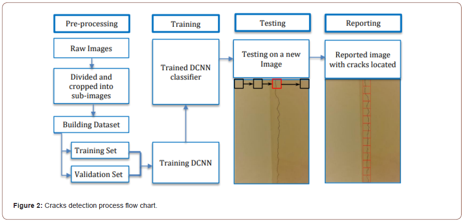
A general crack detection classifier is designed by implementing four important operations: preprocessing, training, testing, and reporting, as illustrated in the following Figure 1. The detailed general crack detection process flow chart is explained in Figure 2. First, raw images are collected and processed to build a databank that is divided into training, validation and testing sets. Second, training and validation sets are used for training the CNN. Third, the trained CNN is tested on new images from the testing set. Finally, detected cracks are reported using a reporting system (Figures 1, 2).

Architecture description
Designing a CNN is the most crucial step in the process of building robust image recognition classifiers. The success of a CNN depends on customizing the architecture design to best fit the given problem. A hand-crafted CNN architecture is a challenging, timeconsuming process that needs many training and validation trials through an optimization process to best tune the architecture layers and hyper parameters. Besides, the need of an expert knowledge, due to the large number of architecture designs choices [48]. Cha et al. [14] proposed CNN architecture that was used in building their crack detection classifier and its training and validation results illustrated to be successful in crack detection problems, which is adopted in this research, while using two different Drop-Out Rates (DORs): 0.5 and 0.3.
The CNN architecture is composed of 14 layers; thus, it is defined as a Deep CNN. The first layer is the input layer of an RGB image of 256 × 256 × 3-pixel resolutions, where each dimension represents height, width and channel (e.g., red, green, and blue), respectively. Input images’ matrices are processed through different convolution, batch normalization (BN), max pooling, and drop-out layers, and are reduced to a 1 × 1 × 96 vector which is then fed into the Rectified Linear Unit (ReLU) layer. Lastly, the softmax layer predicts if the input image has a crack or not after processing the last convolution layer. Table 1 illustrates the detailed dimensions of each layer and operation (Table 1).
Table 1:Dimensions of layers and operations.

Classifier
This section illustrates the classifier building blocks. First, the generation of the training and validation datasets is discussed in section 4.1, with presenting the adopted approach to enlarge the authentic images datasets with synthetic images. Second, the trained DCNNs, their hyper-parameters, training and validation results are discussed in section 4.2. Then, a summary of the used DCNNs and their performance results are provided. This research was performed using ASUS GL552JX machine with CPU: Intel® Core™ i7- 4720HQ @ 2.6GHz, GPU: NVidia® GeForce® GTX 950M (CUDA Toolkit v7.5) and Installed memory (RAM): 16GB. MatConvNet [49] was used to develop this classifier on MATLAB®.
Training and validation data generation
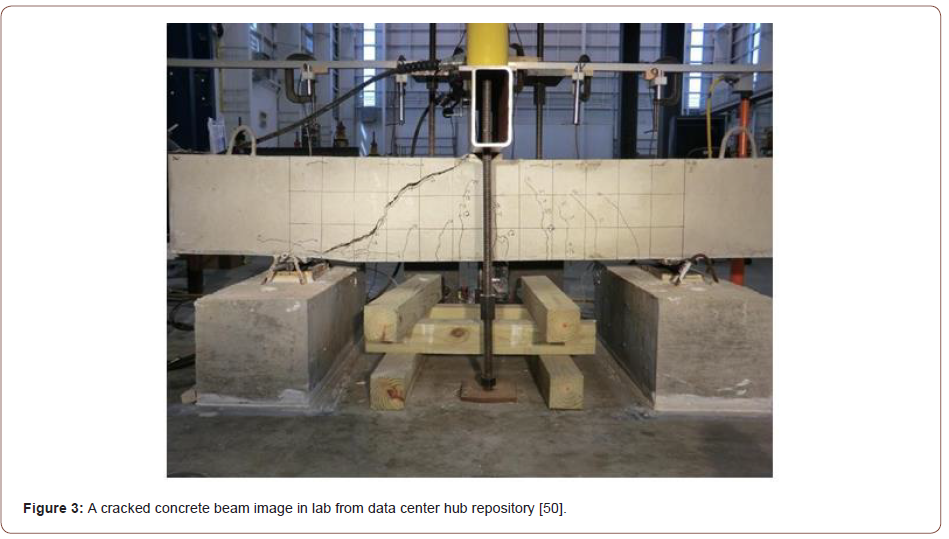
Dataset 1: The first dataset was composed of 115 of raw images which are obtained from data center hub repository provided by Pujol [50]. To add some generalization to the training examples, 3 more raw images were added to the dataset which are obtained from three online sources [51-53]; see Figures. 4(a)-(c). These 118 raw images were cropped and filtered into 2500 cracks sub-images and 8000 background sub-images. In order to enlarge the cracks dataset, data augmentation was used which is a common simple approach that allows enlarging the training data and reducing over-fitting [25]. Data augmentation can be done by translation, rotation or mirroring. In the training and validation dataset 1, data augmentation by vertical mirroring was used with large portion of cracks sub-images, see Figure 5. This allowed nearly doubling the number of cracks sub-images to be 4000 sub-images instead of just 2500 sub-image by mirroring 1500 sub-images. Data augmentation operations over background sub-images was not needed, since the process of cropping the raw images resulted in a sufficient number of background sub-images with respect to cracks sub-images even after its augmentation, and the followed ratio of crack: background was 1:2. The 12000 sub-images were randomly divided into training and validation datasets with a ratio about 4:1 (Figures 3-5).


Dataset 2 using finite element model: Two cracked concrete beams are molded and loaded to cracking using the extended finite element method (XFEM) in ABAQUS software in order to generate synthetic cracks and background images to create the training and validation dataset 2 to use it in the DCNN training. The first concrete beam is a plain concrete beam with dimensions of 600mm and 250 mm for its depth and width respectively. The span of the beam is set to be 5 meters, while being fixed at its two ends. The beams’ concrete modulus of elasticity is set to be 25000 N/ mm2, and the Poisson’s ratio of concrete is 0.3. The second concrete beam is a reinforced concrete beam with dimensions of 600mm and 250 mm for its depth and width respectively. The span of the beam is set to be 5 meters, while being simply supported at its two ends. The beam has two 12mm bars as bottom reinforcement, and two 12mm bars as top reinforcement. The distribution of stirrups is one 8mm bar stirrup at each 200mm. The beams’ concrete modulus of elasticity is set to be 25000 N/ mm2, and 200,000 N/mm2 for steel. The Poisson’s ratio for both concrete and steel is 0.3. The images of the resulting two cracked beams from the finite element models were then cropped and filtered into 3000 sub-images divided into 1000 sub-images of cracks and 2000 sub-images of backgrounds. These synthetically generated sub-images were fed into the training and validation dataset 1 creating a new enlarged dataset of 15000 sub-images with 20% synthetic sub-images. The new enlarged dataset is referred to as training and validation dataset 2, and some examples of it are illustrated here in Figures. 6 and 7. The training sub-images to validation sub- images ratio was maintained to be about 4:1. Table 2 summarizes the training and validation datasets information (Figures 6,7) (Table 2).


Table 2:Dimensions of layers and operations.

DCNNs
Three DCNNs named; DCNN 1.1, DCNN 1.2 and DCNN 2 were developed and trained over training and validation datasets 1 and 2.
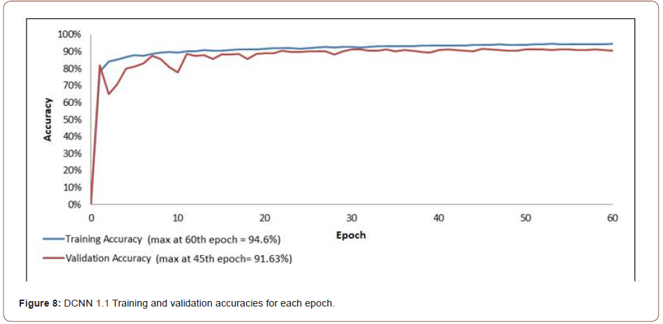
DCNN 1.1: DCNN 1.1 was trained over training and validation dataset 1 using a stochastic gradient descent SGD algorithm with a mini-batch size of 100 out of 12000 images. Weight decay and momentum were assigned by 0.0001 and 0.9. The logarithmically decreasing learning rate was used as recommended by Wilson & Martinez [54]. Dropout rate was assigned by 0.5. The training and validation results of DCNN 1.1 recorded accuracies of 94.6% at the 60th epoch and 91.63% at the 45th epoch, respectively, as illustrated in Figure 8. The training and validation time of 12000 sub-images for 60 epochs was 4 hours and 10 minutes (Figure 8).
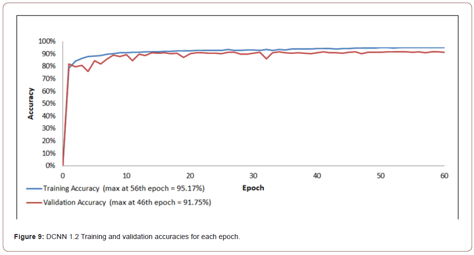
DCNN 1.2: DCNN 1.2 was trained over training and validation dataset 1 using the same algorithm and by having the same hyperparameters assigned as DCNN 1.1, however, dropout rate was reduced to 0.3. The training and validation results of DCNN 1.2 recorded improved accuracies of 95.17% at the 56th epoch and 91.75% at the 46th epoch, respectively, as illustrated in Figure 9. The training and validation time of 12000 sub-images for 60 epochs was 4 hours and 8 minutes (Figure 9).
DCNN 2: DCNN 2 was trained over training and validation dataset 2 using the same algorithm and by having the same hyperparameters assigned as DCNN 1.2. The training and validation results of DCNN 2 recorded improved accuracies of 96.85% at the 59th epoch and 93.15% at the 50th epoch, respectively, as illustrated in Figure 10. The training and validation time of 15000 sub-images for 60 epochs was 5 hours and 59 minutes (Figure 10).
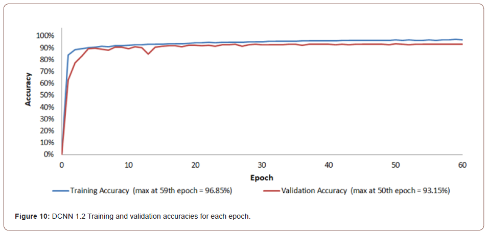
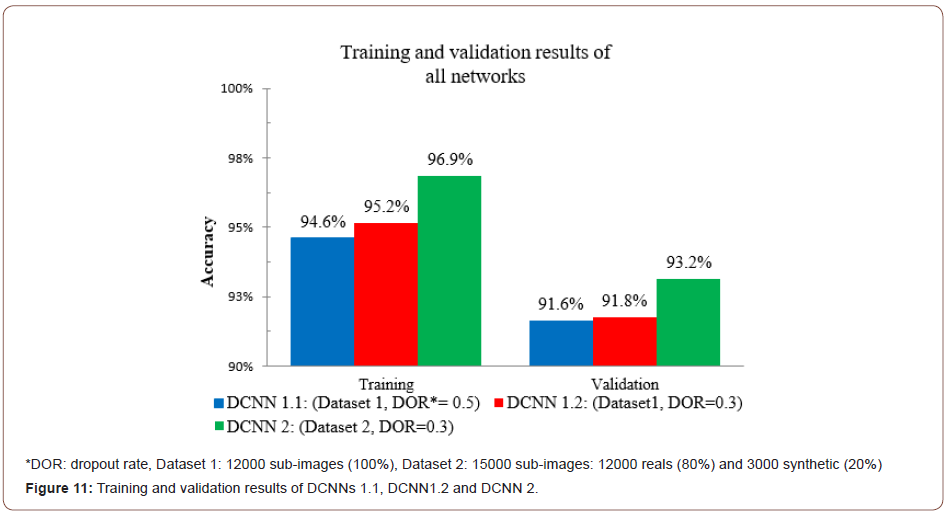
Figure 11 compares the training and validation accuracies of the three proposed DCNNs. Examining the figure indicates that using dropout rate = 0.3 increased the validation accuracy, see DCNN 1.1 and DCNN 1.2 results. Also, Figure 11 indicates that introducing the additional 25% synthetic images has efficiently improved the validation accuracy achieving 93.2% (Figure 11).
Testing
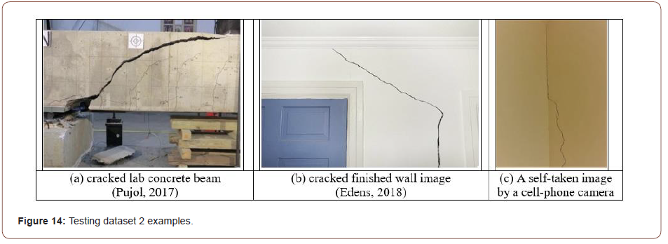
Three different testing images examples are obtained to generate two different testing images datasets to assess the robustness of the trained networks DCNN 1.1, DCNN 1.2 and DCNN 2. These examples include cracked lab concrete beam included in testing datasets 1 and 2, building’s cracks images taken by the author with a cell phone camera included in testing dataset 2, and finished wall cracks image obtained from the internet with complex surroundings included in testing dataset 2.
Testing data generation
Testing dataset 1: 370 unique new sub-images are used, extracted from the lab cracked concrete beams, and which were not used in training. Number of positive images (cracks) is 112. Number of negative images (background) is 258. See examples in Figs. 12 and 13 (Figures 12, 13).


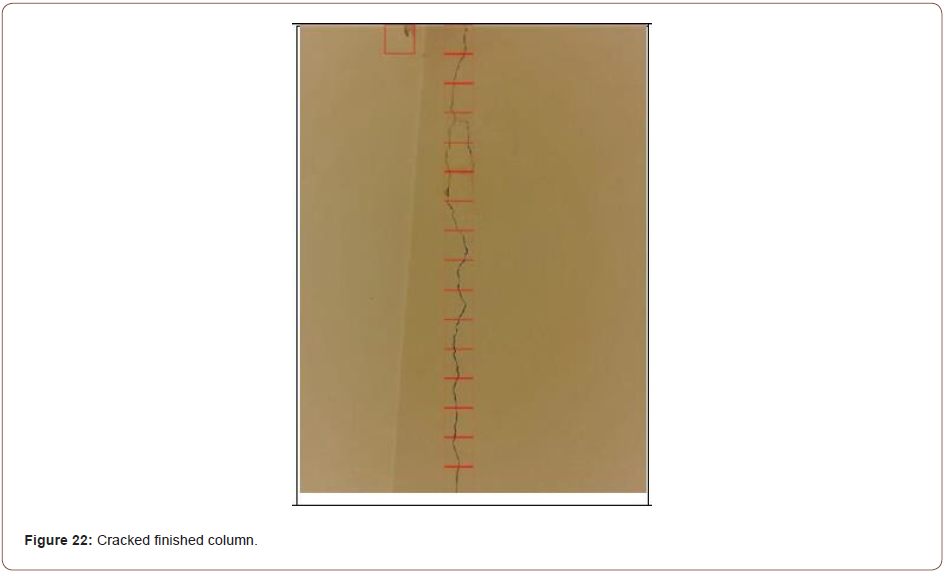
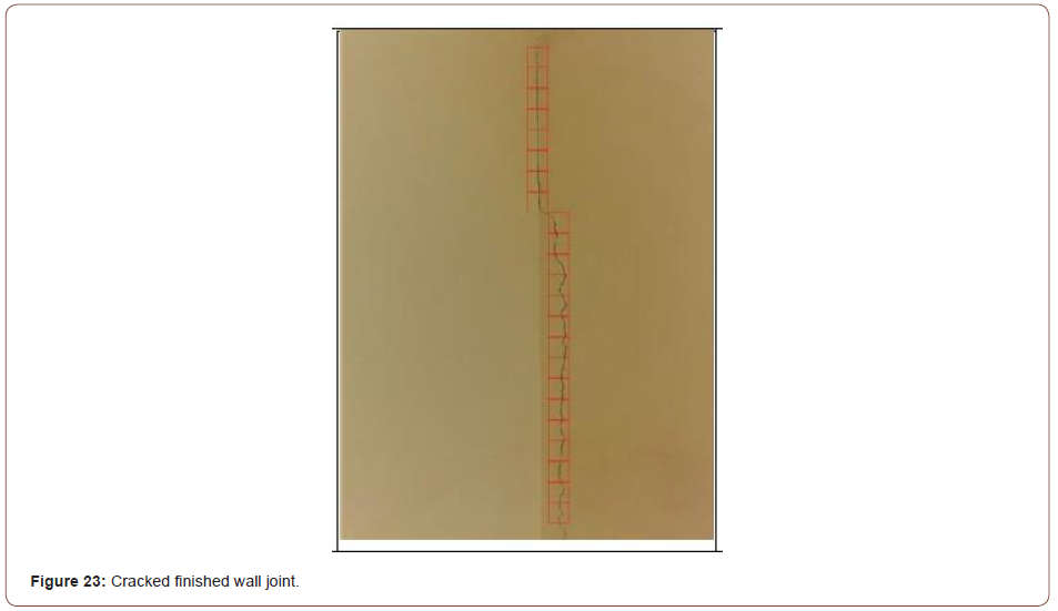
Testing dataset 2: In testing dataset 2, three different raw images examples are used to assess the robustness of the trained networks DCNN 1.2 and DCNN 2, as illustrated in Figures. 14(a)-(c). In order to test DCNNs over raw images, a testing and a reporting system was developed that crop raw images to sub-images for testing then reconstruct the original raw images out the of the tested sub images with reporting their testing results crack or background. Reported sub-images labeled as a crack are highlighted in a red border, while sub-images labeled as a background are reported with no borders. The total number of dataset 2 sub-images is 1618 (Figure 14).
Testing results
Dataset 1 testing results: In this section, the results of testing the three developed DCNNs: DCNN 1.1, DCNN 1.2 and DCNN 2 over testing dataset 1 are illustrated in Figure 15 and summarized in table 3. Also sample of the tested sub-images are provided in Figures 16 & 17. An example of detected cracks in Figure 16 shows effective detection of cracks of different orientations, backgrounds color and textures and a wide range of crack sizes, from wide cracks to hair cracks. Similarly Figure 17 shows an example of the effective detection of different complex backgrounds with wide range of colors, patterns and dark edges that could confuse the network to be detected as cracks. Also, it should be noted the high predictions scores the network achieved in both cases as shown in Figures 16 & 17 (Figures 15-17) (Table 3).
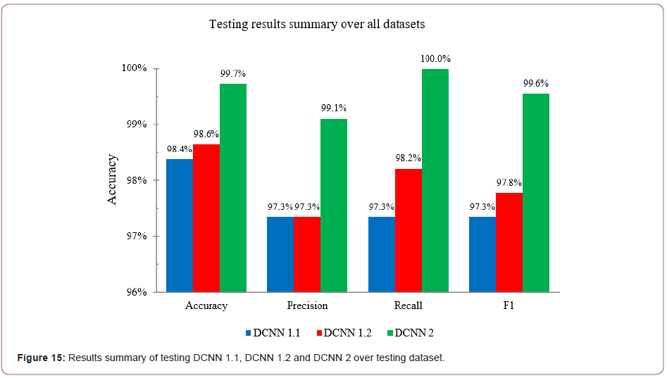
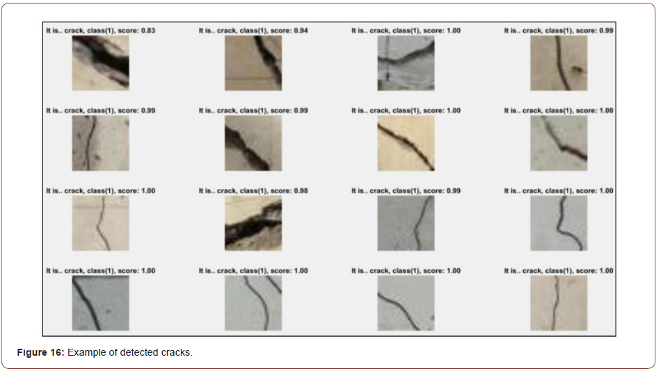
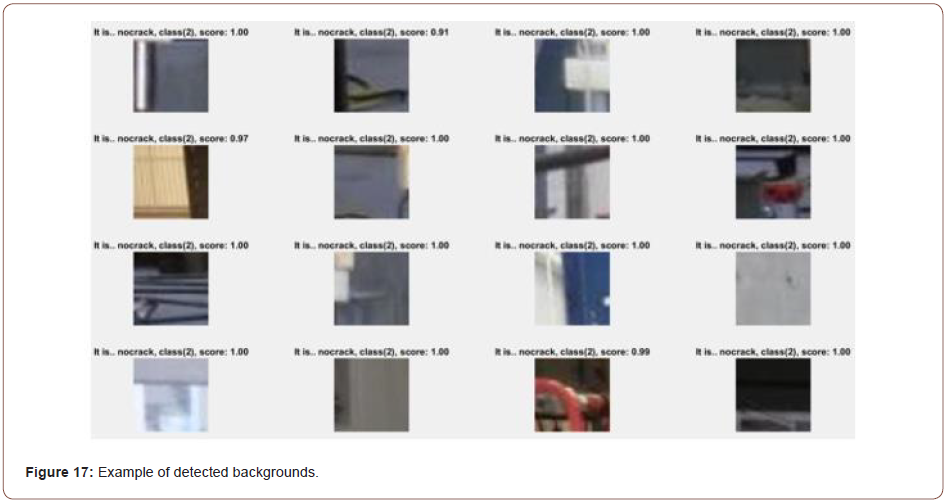
Table 3:Dimensions of layers and operations.

Dataset 2 testing results: In this section, the results of testing the DCNN 1.2 and DCNN 2 over testing dataset 2 are illustrated. The dataset was fed with new 1618 sub-images which has a more of reallife situation images like; cracked lab concrete beam and building’s cracks images and this makes the testing process more challenging, however as shown in Figures 19-23, DCNN 1.2 and DCNN 2 achieved overall accuracies of 97.9% and 98.2%, respectively, see Figure 18. It is shown in Figure 19 how the DCNN 2 could effectively detect cracks while having very complex background. DCNN 2 increase of performance over testing dataset 2 may appear not significant comparing to DCNN 1.2 in terms of absolute values; however, in terms of relative performance, DCNN 2 achieved error reduction of 14.2%, 4.6% and 35.6% in accuracy, precision and recall values, respectively, as illustrated in Figure 18. The testing results are summarized in Tables 4 & 5 (Figures 18-21) (Tables 4,5).
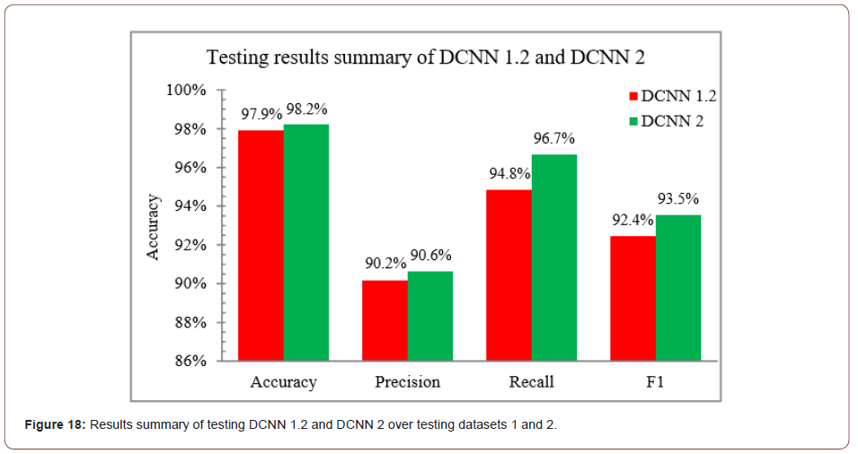
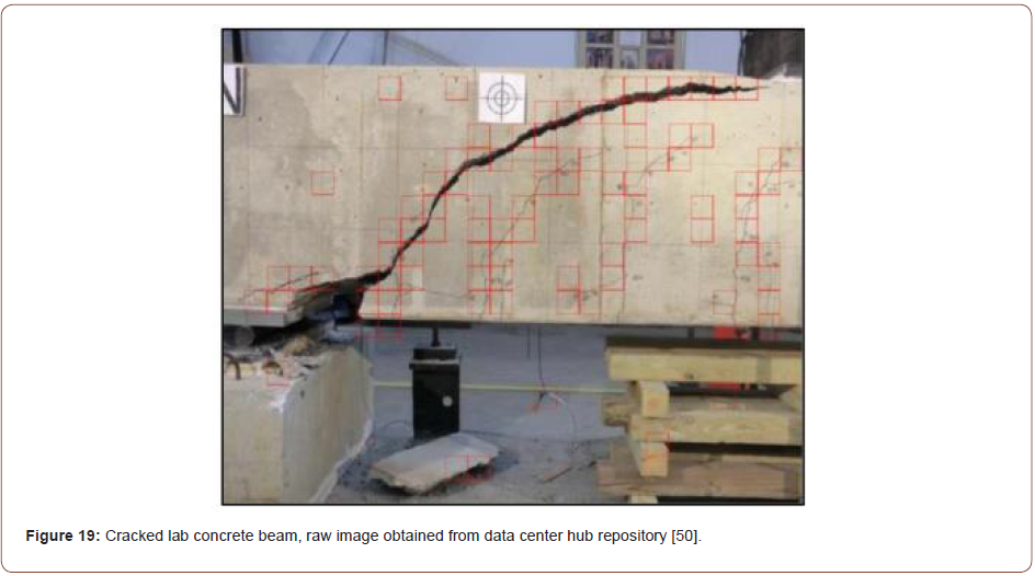
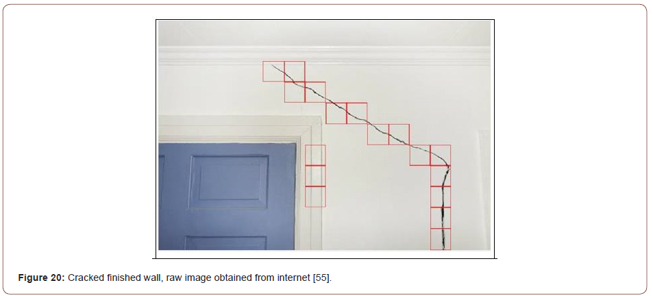
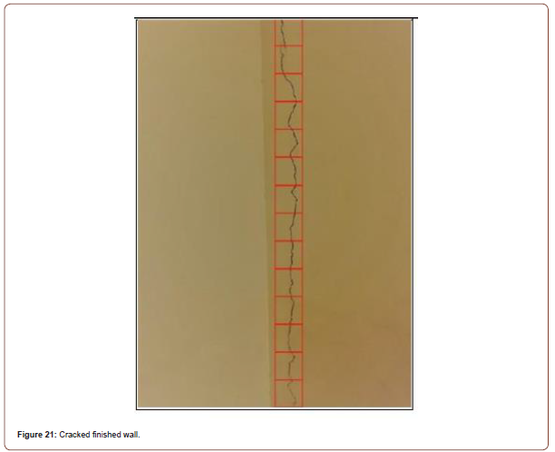
Table 4:Testing results summary of DCNN 1.2.

Table 5:Testing results summary of DCNN 2.

Conclusions
A concrete cracks detection system based on DCNNs is proposed. The training and validation data sets were built on using 118 raw images obtained from the internet. These 118 raw images were cropped and filtered into 12000 sub-images. The first trained network recoded training and validation accuracies 94.6 % and 91.63%, respectively. The network was trained after reducing the dropout rate to 0.3 instead of 0.5 and the network recorded an improved training and validation accuracies of 95.17% and 91.75%, respectively. In order to enlarge the training and validation dataset, synthetic images are added to the original training and validation dataset. The synthetic images were created by modeling two cracked concrete beams using ABAQUS software, and the images of the two beams were cropped and filtered into 3000 sub-images. The new developed synthetic sub-images were added to the original training and validation dataset creating a new enlarged dataset with 15000 sub-images with 20% synthetic images. The ratio between cracks and background sub-images was maintained to be 1:2 respectively. The trained network over the enlarged dataset with synthetic sub-images recorded an improved training and validation accuracies 96.85% and 93.15% respectively. The trained networks were tested over different testing images’ examples such as: (i) Images of cracked concrete beam in lab with complex surroundings like cables, windows, bearings, etc. (ii) Images of finished walls. The testing results showed the robustness of the proposed system in detecting concrete cracks in environments with complex backgrounds. The effectiveness of using synthetic images in enlarging crack training and validation datasets, and their positive impact in increasing the testing accuracy was illustrated. The trained network over 15000 sub-images with 20% synthetic sub-images recorded an average testing accuracy, precision and recall 98.2%, 90.6%, 96.7% respectively on a wide range of testing images with a total of 1988 sub-images. The proposed system was developed with a reporting system that facilitated and automated the testing process. Moreover, this system could be combined with remote control drones to facilitate and accelerate the process of damage detection and inspection of civil infrastructures, as a replacement of the routine on-site visual inspection process of civil structures. In future research work, a Deep CNN based system could be developed to detect and classify various concrete cracks/ damage types.
Acknowledgement
None.
Conflict of Interest
No conflict of interest.
References
- Aboudi J (1987) Stiffness reduction of cracked solids. Engineering Fracture Mechanics 26(5): 637–650.
- Doherty JE (1987) Nondestructive Evaluation. Chapter 12 In: Handbook on Experimental Mechanics, AS Kobayashi (Ed.) Society for Experimental Mechanics Inc., Bethel, Connecticut, USA.
- Doebling SW, Farrar CR, Prime MB (1998) A summary review of vibration-based damage identification methods. Shock Vib Digest 30(2): 91-105.
- Rabinovich D, Givoli D, Vigdergauz S (2007) XFEM-based crack detection scheme using a genetic algorithm. International Journal for Numerical Methods in Engineering, 71(9): 1051–1080.
- Chatzi EN, Hiriyur B, Waisman H, Smyth AW (2011) Experimental application and enhancement of the XFEM–GA algorithm for the detection of flaws in structures. Computers and Structure 89(7-8): 556–570.
- Cha YJ, Buyukozturk O (2015) Structural Damage Detection Using Modal Strain Energy and Hybrid Multiobjective Optimization. Computer-aided Civil and Infrastructure Engineering 30(5): 347–358.
- Teidj S, Khamlichi A, Driouach A (2016) Identification of Beam Cracks by Solution of an Inverse Problem. Procedia Technology 22: 86–93.
- Hou J, Wang H, Xu D, Jankowski Ł, Wang P (2020) Damage identification based on adding mass for liquid–solid coupling structures. Applied Sciences 10(7): 2312.
- Yoon H, Elanwar H, Choi H, Golparvar-Fard M, Spencer BF (2016) Target-free approach for vision-based structural system identification using consumer-grade cameras. Structural Control and Health Monitoring 23(12): 1405–1416.
- Abdel-Qader I, Pashaie-Rad S, Abudayyeh O, Yehia S (2006) PCA-Based algorithm for unsupervised bridge crack detection. Advances in Engineering Software 37(12): 771–778.
- Yamaguchi T, Hashimoto S (2010) Fast crack detection method for large-size concrete surface images using percolation-based image processing. Mach Vision Appl 21 (5): 797–809.
- Prasanna P, Dana K, Gucunski N, Basily B (2012) Computer-vision based crack detection and analysis. SPIE Smart Structures and Materials + Nondestructive Evaluation and Health Monitoring, San Diego, California, United State, April.
- Chen JG, Wadhwa N, Cha YJ, Durand F, Freeman WT, et al. (2015) Modal identification of simple structures with high-speed video using motion magnification. Journal of Sound and Vibration 345: 58–71.
- Cha YJ, Choi W, Büyüköztürk O (2017) Deep Learning-Based Crack Damage Detection Using Convolutional Neural Networks. Computer-aided Civil and Infrastructure Engineering 32(5): 361–378.
- Koch C, Georgieva K, Kasireddy V, Akinci B, Fieguth P (2015) A review on computer vision-based defect detection and condition assessment of concrete and asphalt civil infrastructure. Advanced Engineering Informatics 29(2): 196–210.
- Cha YJ, You K, Choi W (2016) Vision-based detection of loosened bolts using the Hough transform and support vector machines. Automation in Construction 71: 181–188.
- Rose P, Aaron B, Tamir D, Lu L, Hu J, et al. (2014) Supervised Computer-Vision-Based Sensing of Concrete Bridges for Crack-Detection and Assessment. Transportation Research Board 93rd Annual Meeting Compendium of Papers, Washington DC, USA.
- Lecun Y, Bottou L, Bengio Y, Haffner P (1998) Gradient-based learning applied to document recognition. Proceedings of the IEEE 86(11): 2278–2324.
- O Byrne M, Ghosh B, Schoefs F, Pakrashi V (2014) Regionally Enhanced Multiphase Segmentation Technique for Damaged Surfaces. Computer-aided Civil and Infrastructure Engineering 29(9): 644–658.
- Wu L, Mokhtari S, Nazef A, Nam B, Yun HB (2014) Improvement of crack-detection accuracy using a novel crack defragmentation technique in image-based road assessment. Journal of Computing in Civil Engineering, 30(1): 04014118-1 to 04014118-19.
- Jahanshahi MR, Masri SF, Padgett CW, Sukhatme GS (2013) An innovative methodology for detection and quantification of cracks through incorporation of depth perception. Machine Vision and Applications 24(2): 227–241.
- O Byrne M, Schoefs F, Ghosh B, Pakrashi V (2013) Texture Analysis Based Damage Detection of Ageing Infrastructural Elements. Computer-aided Civil and Infrastructure Engineering 28(3): 162–177.
- Moon HG, Kim JH (2011) Intelligent Crack Detecting Algorithm on the Concrete Crack Image Using Neural Network. Proceedings of the 28th ISARC. Seoul, Korea.
- Ciresan DC, Meier U, Masci J, Maria Gambardella L, Schmidhuber J (2011) Flexible, high performance convolutional neural networks for image classification. Proceedings of the 22nd International Joint Conference on Artificial Intelligence, Barcelona, Catalonia, Spain, July 16-22.
- Krizhevsky A, Sutskever I, Hinton GE (2012) Imagenet classification with deep convolutional neural networks. Proceedings of the 25th International Conference on Neural Information Processing Systems, Lake Tahoe, Nevada, USA, December,1097–1105.
- Simard PY, Steinkraus D, Platt JC (2003) Best practices for convolutional neural networks applied to visual document analysis. Proceedings of the Seventh International Conference on Document Analysis and Recognition, Edinburgh, Scotland, UK, August.
- Lecun Y, Bengio Y, Hinton G (2015) Deep learning. Nature, 521(7553): 436–444.
- Lee D, Kim J, Lee D, (2019) Robust Concrete Crack Detection Using Deep Learning-Based Semantic Segmentation. International Journal of Aeronautical and Space Sciences 20: 287–299.
- Alipour M, Harris DK (2020) Increasing the robustness of material-specific deep learning models for crack detection across different materials. Engineering Structures 206: 110157.
- Deng J, Lu Y, Lee VC (2020) Concrete crack detection with handwriting script interferences using faster region‐based convolutional neural network. Computer-aided Civil and Infrastructure Engineering 35(4): 373–388.
- Li B, Wang KCP, Zhang A, Yang E, Wang G (2020) Automatic classification of pavement crack using deep convolutional neural network. International Journal of Pavement Engineering 21(4): 457–463.
- Yang Q, Jiang S, Chen J, Lin W (2020) Crack detection based on ResNet with spatial attention. Computers and Concrete, 26(5): 411–420.
- Abdel-Qader I, Abudayyeh O, Kelly ME (2003) Analysis of edge-detection techniques for crack identification in bridges. Comput. Civil Eng. 17 (4): 255–263.
- Yamaguchi T, Nakamura S, Saegusa R, Hashimoto S (2008) Image-Based Crack Detection for Real Concrete Surfaces. IEEJ Transactions on Electrical and Electronic Engineering 3(1): 128–135.
- Lattanzi D, Miller GR (2014) Robust automated concrete damage detection algorithms for field applications. J Comput Civ Eng 28 (2): 253–262.
- Torok MM, Golparvar-Fard M, Kochersberger KB (2014) Image-based automated 3D crack detection for post-disaster building assessment. J Comput Civil Eng 28 (5): A4014004.
- Simler C, Trostmann E, Berndt D (2019) Automatic crack detection on concrete floor images. SPIE 11144, Photonics and Education in Measurement Science, Jena, Germany, September.
- Al-Salloum YA, Shah AA, Abbas H, Alsayed SH, Almusallam TH, et al. (2012) Prediction of compressive strength of concrete using neural networks. Computers and Concrete 10(2): 197–217.
- Asteris PG, Apostolopoulou M, Skentou AD, Moropoulou A (2019) Application of artificial neural networks for the prediction of the compressive strength of cement-based mortars. Computers and Concrete 24(4): 329–345.
- LeCun Y, Cortes C, Burges CJ (2010) MNIST handwritten digit database.
- Deng J, Dong W, Socher R, Li LJ, Kai Li, et al. (2009) ImageNet: A large-scale hierarchical image database.
- Krizhevsky A (2009) The CIFAR-10 and CIFAR-100 datasets.
- Steinkraus D, Buck I, Simard PY (2005) Using GPUs for machine learning algorithms. Eighth International Conference on Document Analysis and Recognition (ICDAR'05): Seoul, South Korea, August 29–September 1.
- Zhang L, Yang F, Daniel Zhang Y, Zhu YJ (2016) Road crack detection using deep convolutional neural network. 2016 IEEE International Conference on Image Processing (ICIP): Phoenix, AZ, USA, September.
- Yokoyama S, Matsumoto T (2017) Development of an automatic detector of cracks in concrete using machine learning. Procedia Engineering 171: 1250–1255.
- He K, Zhang X, Ren S, Sun J (2016) Deep residual learning for image recognition. Proceedings of the IEEE Conference on Computer Vision and Pattern Recognition, Boston, MA, USA, pp. 770–778.
- ABAQUS (2014) Version 6.14 User’s Manual, Dassault Systèmes Simulia Corp.; Providence, RI, USA.
- Albelwi S, Mahmood A (2017) A framework for designing the architectures of deep convolutional neural networks. Entropy 19(6): 242.
- Vedaldi A, Lenc K (2015) MatConvNet: convolutional neural networks for MATLAB. Proceedings of the 23rd ACM International Conference on Multimedia, Brisbane, Australia, October 26–30: 689–692.
- Pujol S (2017) The Effect of Scale on the Resistance of Reinforced Concrete Beams to Shear (NEES-2012- 1169). Database in Data center Hub; West Lafayette, Indiana, USA.
- Tilt-Up Concrete Association (2012) Tilt-Up today; Tilt-Up Concrete Association, Mount Vernon, USA.
- Rick (2009) Concrete texture with crack; Flicker, San Francisco, USA.
- Greene’s Inc. (2020) 2 ways utah weather can hurt concrete; Greene’s Inc., USA lake, Salt.
- Wilson DR, Martinez TR (2001) The need for small learning rates on large problems. Proceedings of International Joint Conference on Neural Networks, Washington DC, USA, July.
- Edens D (2018) 5 signs foundation crack; Edens Structural Solutions, Bixby, USA.
-
Mohamed Elmorsy, Hazem Elanwar, Ahmed Elbanna, Sherif A Mourad et al. Crack Detection in Environments with Complex Backgrounds Using Deep Convolution Neural Nets. Cur Trends Civil & Struct Eng. 8(4): 2022. CTCSE.MS.ID.000694. DOI: 10.33552/CTCSE.2022.08.000694.
-
Civil engineering, Damaging disasters, Designs, Constructions, Material technologies, Bridge
-

This work is licensed under a Creative Commons Attribution-NonCommercial 4.0 International License.


