 Review Article
Rapid Construction Method for Bridges with Long- Span Precast Girders Made of C80/95
Jens Heinrich1*, Reinhard Maurer2, Theo Reddemann3 and Till Schnetgöke3
1KHP Dortmund, Germany
2Formerly TU Dortmund University, KHP Dortmund, Germany
3Construction company Gebr Echterhoff GmbH & CO KG, Industriestraße, Germany
Jens Heinrich, Department of Civil Engineering, KHP Dortmund, Germany
Received Date:February 15, 2024; Published Date:March 04, 2024
Abstract
Fast construction with the least possible traffic disruptions in connection with a minimization of congestion-related CO2 emissions represent a new design goal for concrete bridges in Germany today under the banner of sustainable construction and climate protection. In the following article, the potential of prestressed high-strength concrete C80/95 for precast girders in an overpass structure over a 6-lane motorway without the need for an intermediate support in combination with the use of precast elements also for the abutments is reported as a pilot project. The article concludes with the remarkable result of a study on how much CO2 emissions can potentially be avoided by shortening the construction time of such structures.
Keywords:Pilot project; rapid construction; high-strength concrete; Prefabricated construction; Hybrid caps; CO2 emissions
Introduction
The use of high-strength concrete in conjunction with prestressing
significantly expands the possibilities of building with
concrete in bridge construction as well, as shown by the pilot project
presented in this article in precast construction with in-situ
concrete supplementation. In order to minimise traffic disruptions
and congestion-related CO2 emissions, the construction method
with the long-span precast girders made of C80/95 was combined
with the Echterhoff express construction method in the pilot project.
This resulted in a groundbreaking and innovative new construction
method for prefabricated bridges in Germany. Basically,
the high strengths of the C80/95 result in the following advantages:
a. Increased load-bearing resistance
b. In combination with a preload, significantly larger spans or
slenderness
c. Reduction of dead loads and lower quantities of concrete due
to smaller cross-sectional dimensions.
d. Savings in the start-up area due to lower dead burdens.
This potential enables, for example, overpass structures over 6-lane motorways without intermediate support as single-span girders with a span of approx. 45 m. Internationally, high-strength concrete was initially used in bridges, primarily in North America, France and Norway. The motivation was by no means only strength aspects, but also the immense possibilities for improving durability. An example of the potential of high-strength concrete is the Raftsund Bridge, a curved beam with a main span of approx. 300 m, built in Norway in 1998 [1]. In Germany, a number of smaller structures were initially carried out as pilot projects in high-performance concrete [2]. In 2002, the bridge over the Zwickauer Mulde near Glauchau was implemented as the first pilot project for the use of high-performance concrete in the construction of large bridges using in-situ concrete construction [3]. With a maximum span of 39.00 m, the structure has a structural cross-section height of only 1.05 m, corresponding to a maximum bending slenderness of

After completion, this structure was extensively monitored under static and dynamic test loads as well as to investigate the longterm deformation behaviour of the high-strength concrete C70/85 [4]. The monitoring showed a flawless structural behaviour under the test loads as well as essentially a confirmation of the standard- compliant design approaches for creep and shrinkage. Of decisive importance for the unerring production of the C70/85 as in-situ concrete were the accompanying quality assurance measures.
In principle, both an integral frame and a single-span girder are feasible for the transfer over a 6-lane motorway without intermediate support. The integral design allows for greater slenderness, but entails additional forced internal forces, the size of which is also decisively influenced by the substrate stiffness. The ground is part of the integral structure. With regard to the stiffnesses to be applied, it contains the greatest uncertainties in the overall system, which must be taken into account in an appropriate form when determining internal forces, for example by applying upper and lower limit values.
Since subsidence is to be expected in large areas of the Ruhr area, statically certain load-bearing systems are preferred. For this reason, a statically determined single-span girder system was chosen as the supporting structure for the pilot project.
Pilot project Amelsbürener Straße
Description of the building
In the course of the planned 6-lane expansion of the A1 motorway, a total of 15 replacement overpass structures were required in the motorway section between the Ascheberg and Münster-Hiltrup exits. In the case of the overpass structure on Amelsbürener Straße, a further pilot project was carried out in which the prefabricated construction method was to be tested outside the previous area of experience. The existing two-span bridge with spans of 2 x 20.65 m was replaced by a single-span bridge with prefabricated elements with a total length of 45 m. Amelsbürener Straße is thus the first overpass structure in Germany as a structurally determined single-span girder over a motorway without a central support in concrete construction with prefabricated elements with a span of 45 m. The substructures were designed as box-shaped abutments. The central support of the existing structure was completely omitted for the replacement building. The abutments were laid flat. The normative reference for design and construction was Eurocode 2 [5], in the version valid for Germany.
Planning and execution Bases
A key planning principle of this construction project was to minimise construction times. This can be achieved in particular by shifting work steps from the construction site to prefabrication. Therefore, possibilities were sought as to how a large proportion of precast elements could be used, but without influencing the monolithic load-bearing behaviour too much by too many joints.
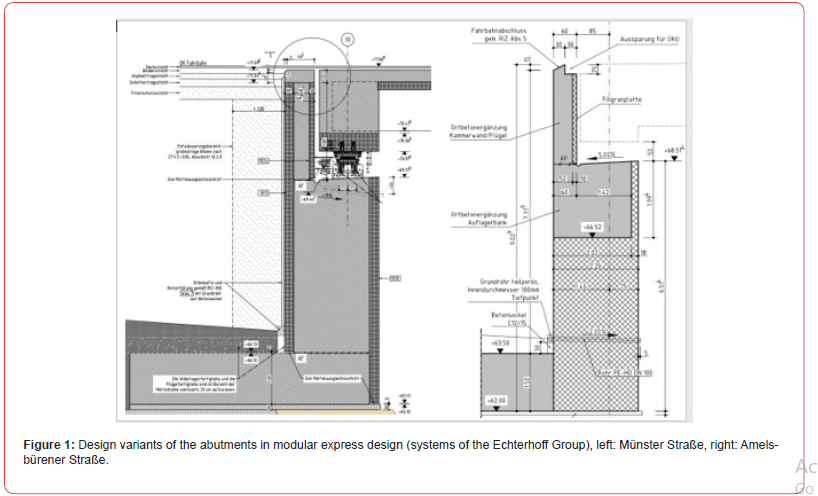
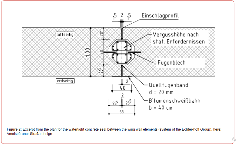
In the case of the substructures of the Echterhoff express construction method, two different design variants were developed, which are briefly described in this report (Figure 1). In variant 1, the sash walls consist of fully prefabricated elements with a one-sided connection reinforcement in the lower area for a force-fit connection with the in-situ concrete slab. The foundation slab is made of in-situ concrete. The wing elements serve as lateral formwork. These are thus connected to each other via the foundation plate. To ensure that the relative deformations in the head area of the sash wall elements remain small during use, reinforced concrete seals are arranged between the individual elements in profiled joints for the transmission of shear forces (Figure 2). Semi-prefabricated elements are used for the production of the abutment and chamber walls, which serve as lost formwork and are only statically applied to absorb the concreting loads. The wall core, made of in-situ concrete, takes over the entire load-bearing portion. The semi-finished parts are bonded to the monolithic wall cross-section in a shear-resistant manner.
In the case of the Amelsbürener Straße bridge, the substructures were built according to variant 2. While the abutment wing walls were erected using fully prefabricated elements with in-situ concrete seals, as in variant 1, the abutments were manufactured according to a modified design. A large part of the abutment walls is now prefabricated in the factory. The lower area of the wall elements was already pre-concreted in the factory, so that significantly more solid wall elements are created. As with the sash elements, the connection to the base plate is made by means of a corresponding connection reinforcement. In the upper area of the abutments, only an approx. 1.50 m high support beam in in-situ concrete construction is realized, which connects the abutment walls to each other in a shear-resistant manner and can ensure the load transfer from the bearings (Figure 1). The air-side facing shells, which serve as formwork for the support beam, are already arranged in the prefabricated elements, which ensures a high quality of exposed concrete.
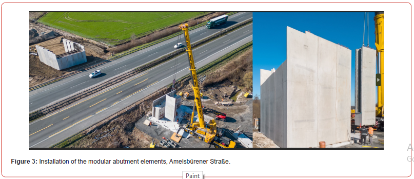
The assembly of the prefabricated reinforced concrete elements of this abutment structure, including the wing walls, was completed within 20 working hours on each side of the abutment. The subsequent supplementary work in the area of the reinforced concrete base and the in-situ concrete supplementary beam could be carried out in a very short time distance of approx. 6 working days. During the construction of the bridge abutments, there were no traffic disruptions on the A1 motorway (Figure 3).
Superstructure
In order to limit the dead weight of the precast girders, a highstrength concrete of grade C80/95 was used. In addition, it was necessary to optimize the cross-sectional shape of the finished parts so that a permissible total weight for production in the precast plant of approx. 110 tons would not be exceeded. For this purpose, the web cross-section was reduced to 35 cm in the field area and widened to the total cross-section width of 85 cm in the area of the supports. In order to avoid harmful deposits on the foot extensions of the lower chords, the transition from the hammer-head-shaped foot flares of the lower chords to the bridge area below 60° was planned (Figure 4).
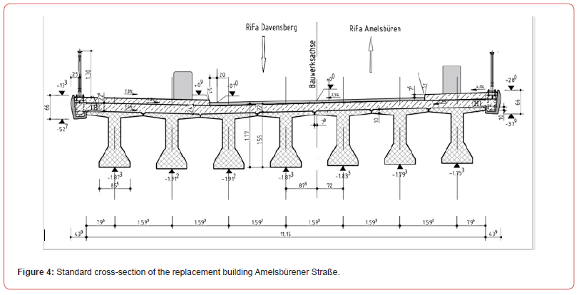
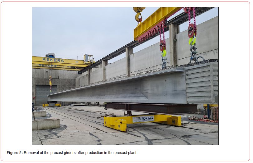
The prestressing of the precast elements consisted of a prestressing bed and two parabolic tendons arranged in steel sheathing tubes (subsequent bonding). The preload of the fitted bed could be arranged in the foot extension. However, the dead weight of the precast elements was so great that the prestressed bed post-tensioning could be dimensioned just enough to ensure decompression during excavation from the formwork (Figure 5). In order to prevent excessive deflection of the finished parts during storage, a partial preload of the subsequent prestressing was applied shortly after the production of all beams. The application of the remaining prestressing force and the grouting of these tendons was only carried out on the construction site after the in-situ concrete supplement had hardened. With a centre distance of 1.60 m between the prefabricated elements, a total of 7 longitudinal beams were required for the approx. 12 m wide superstructure.
Hybride Edge Beams
The origin of the hybrid caps comes from the requirement or considerations to keep the interference of current traffic as low as possible due to the construction work. In the case of conventional construction methods, the canopies are made above the flowing traffic by means of formwork scaffolding. The work processes required for this, at least for the stripping work and some bridge equipment, require traffic closures of the underlying tracks during the construction period. In the case of the construction of a road overpass over a railway line, a closure of the underlying railway line is necessary solely for the stripping work of the cap formwork. The same applies to the construction of a road overpass over a motorway or road. In order to counteract these traffic restrictions, the hybrid canopy was designed to serve as a formwork for concrete paving on the one hand and as a supporting element for railings, contact protection or noise barriers on the other. With the addition of the hybrid canopy construction and, for example, attached railings, which already serve as fall protection during the construction phase, all further bridge construction work can be carried out from a protected space from the bridge slab, without further traffic closures of the underlying driveways.
Usually, the hybrid canopies are designed, constructed and executed as a pure steel structure according to the rules of steel construction. The steel formwork element of the hybrid cap forms the outer boundary of the canopy construction as a lost formwork. The construction consisting of formwork element and swords for fastening to the superstructure also serves as a supporting element for railing, contact protection or noise barrier constructions in the state of assembly. The canopies are reinforced and are connected to the superstructure by means of cap connection reinforcement. Therefore, the load transfer of the concreted caps corresponds to the general state of the art in Germany.
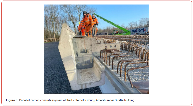
The steel formwork elements, which are visible from the outside, have an anti-corrosion coating. Another pilot aspect in this bridge construction project is the formation of the hybrid canopy construction made of carbon concrete. Since the coatings of the steel hybrid canopy constructions can be affected in the event of collision damage and thus lead to corrosion damage, a canopy construction using carbon concrete was developed at the request of the client, which is not susceptible to corrosion (Figure 6). The reinforcement of the canopy with carbon (carbon fibers) was deliberately chosen for corrosion protection reasons, as carbon fibers cannot corrode. A further advantage lies in the minimum concrete cover, which can be much lower when using carbon for the aforementioned reason and thus contributes significantly to the weight and cross-section reduction of the wall thicknesses of the hybrid canopy, or allows it.
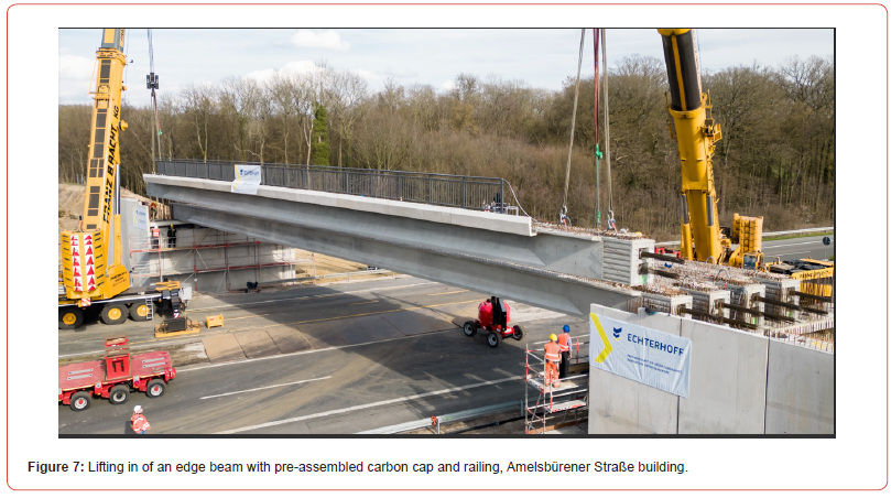
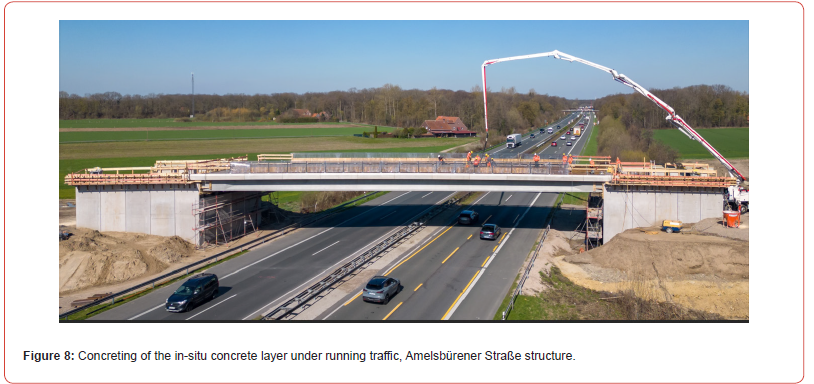
Since a pre-assembly of the carbon concrete cap in the precast plant would have led to a significant increase in the transport weights for the bridge girders, the bridge were equipped with the carbon concrete caps including the railing constructions at a motorway site close to the construction site 2 days before the assembly date and then installed in the final position (Figure 7). Thanks to this approach, installation of the bridge girders including the railings as fall protection, all further work such as supplementing the reinforcement of the end cross beams and the road slab, as well as the supplementary concrete for the bridge slab, could be carried out from above the protected space (Figure 8). For this reason, further motorway closures were no longer necessary. The patent-protected “hybrid cap” design was developed by the construction company Echterhoff.
Contribution to sustainability and climate protection
Cement production accounts for 8% to 9% of global CO2 emissions. For this reason, we rightly have to look at new, CO2-reduced cement production methods. But what influence do bridge construction work in the course of the motorway have on traffic obstructions and thus on the generation of CO2 emissions due to traffic jams? How does this compare replacement bridge construction work in modular construction with a total construction time of 6 to 8 months compared to conventional construction methods with a construction time of 24 months? The independent studies of the Ruhr University Bochum [6] and the RWTH Aachen University [7] in cooperation with the construction company Gebr. Echterhoff come to a common, very astonishing (concise) result. In his study [6], a life cycle analysis over 100 years from the start of construction to the dismantling of a bridge in the course of a motorway, Prof. Mark comes to the conclusion that with the increase in construction time, CO2 emissions also increase drastically as a result of the traffic jams associated with the construction period. The basis for this finding is the recording of traffic congestion over a period of 24 months during the construction of a 200 m long replacement bridge structure. With a daily traffic load of 45,000 vehicles, the total share of CO2 emissions in the first 2 years during the construction period is 83% in relation to the entire life cycle of 100 years.
Cement production accounts for 8% to 9% of global CO2 emissions. For this reason, we rightly have to look at new, CO2-reduced cement production methods. But what influence do bridge construction work in the course of the motorway have on traffic obstructions and thus on the generation of CO2 emissions due to traffic jams? How does this compare replacement bridge construction work in modular construction with a total construction time of 6 to 8 months compared to conventional construction methods with a construction time of 24 months? The independent studies of the Ruhr University Bochum [6] and the RWTH Aachen University [7] in cooperation with the construction company Gebr. Echterhoff come to a common, very astonishing (concise) result. In his study [6], a life cycle analysis over 100 years from the start of construction to the dismantling of a bridge in the course of a motorway, Prof. Mark comes to the conclusion that with the increase in construction time, CO2 emissions also increase drastically as a result of the traffic jams associated with the construction period. The basis for this finding is the recording of traffic congestion over a period of 24 months during the construction of a 200 m long replacement bridge structure. With a daily traffic load of 45,000 vehicles, the total share of CO2 emissions in the first 2 years during the construction period is 83% in relation to the entire life cycle of 100 years.
Summary
With the planning and execution of the Amelsbürener Straße bridge in prefabricated construction, a modular express construction method was successfully implemented for both the superstructures and the substructures. Two different design variants were presented for the production of the substructures, which can significantly shorten construction times due to a large factory prefabrication. Both pilot projects have achieved immense reductions in construction times. The superstructure was constructed with prestressed prefabricated elements made of highstrength concrete (C80/95). With the replacement construction of Amelsbürener Straße, the full potential of these high-strength prestressed precast girders was subsequently exploited when an overpass of a 6-lane motorway was realized without intermediate support. The total weight of these precast longitudinal beams was up to 110 tons. By using special hybrid caps made of steel or carbon concrete, the construction time can be reduced even further. The hybrid canopies can be mounted on the edge girders before they are lifted, eliminating the need for additional formwork work. Railings and noise barriers can also be pre-assembled. The great influence of the construction time on CO2 emissions has been shown in various studies. This clearly shows that the shorter the construction time of replacement bridge structures while traffic is running, the lower the enormous CO2 pollution from traffic jams.
References
- Ewert S (2003) Bridges – The Development of Spans and System. Ernst & Sohn.
- Bernhardt K, Brameshuber W, King G, Krill A, Zink M (1998) Prestressed high-performance concrete: First application in Germany in the Sasbach pilot project. Concrete and Reinforced Concrete Construction 94(5): 216-223.
- King G, Weigel F, Zinc M, Arnold A, Maurer R (2002) First large German bridge made of high-performance concrete - bridge over the Zwickauer Mulde near Glauchau. Concrete and Reinforced Concrete Construction 97(6): 303-307.
- Maurer R, Weigel F, Arnold A (2005) Structural monitoring of a bridge made of high-performance concrete. Concrete and Reinforced Concrete Construction 100(3): 195-206.
- Eurocode 2: Design and construction of reinforced concrete and prestressed concrete structures - Part 2: Concrete bridges, design and construction rules.
- Richter C, Reddemann T (2022) Saving CO2 emissions by shortening construction time using the example of the Afferder Weg / A1 construction project. Study. Center Building an Infrastructure Engineering of the RWTH Aachen Campus.
- Hoppe J, Forman P, Mark P (2022) CO2 balancing over the building life cycle. Chair of Concrete Construction, Ruhr University Bochum.
-
Jens Heinrich*, Reinhard Maurer, Theo Reddemann and Till Schnetgöke. Rapid Construction Method for Bridges with Long- Span Precast Girders Made of C80/95. Cur Trends Civil & Struct Eng. 10(4): 2024. CTCSE.MS.ID.000743.
-
Pilot project; rapid construction; high-strength concrete; Prefabricated construction; Hybrid caps; C02 emissions; Iris Publishers, Iris Indexing Sites
-

This work is licensed under a Creative Commons Attribution-NonCommercial 4.0 International License.


