


 Research Article
Geologic and Geotechnical Investigation for Engineering Design of Foundation Systems at the Federal University, Otuoke, Bayelsa State, Nigeria
Received Date:March 08, 2023; Published Date:March 29, 2023
Abstract
This study aims at assessing the sub-soil condition for design of foundation systems at the Federal University, Otuoke, Bayelsa State, Nigeria. A total of eighteen (18) soil borings employing the standard penetration testing (SPT) each to a depth of 30.0m and twenty-nine (29) shallow borings (3.00 m deep) were made at pre-selected positions across the entire area of the Federal University, Otuoke, Bayelsa State. On the basis of field investigations and laboratory testing carried out on the soil samples obtained from the project site, it is observed that five (5) identifiable soil horizons are present and this are namely: Brownish clayey layer (CL) - [top soil], greyish organic silty clays (OL), greyish clayey silty sands (SM) and (SC-SM), yellowish to whitish silty sands (SM) and well-graded sands and gravels (SW). The obtained value for the bearing capacity for continuous strip footings to be used at the Project Site is about 153.35 + 1.483B [kPa] where B = width of the structure to be built. For a B = 5.00 meters, the bearing capacity has been found to be 160.76 kPa. The recommended depth of emplacement of continuous strip footings is 0.75 meters. This value represents the bearing capacity of the upper bearing lateritic clays and silty clays at the project site. The range of values obtained for the bearing capacity for raft footings at the project site, based on the conventional SPT Method, is between 76.55 and 208.86 kPa with an average of 122.85 kPa. The recommended depth of emplacement of raft footings is 1.50 meters. This value represents the bearing capacity of the upper bearing lateritic clays and silty clays at the project site. Since the buildings at the University Campus may subjected to live loads from the movements of different numbers of students in a continuously day-to-day fashion over the years, the potentials of the silty soils becoming liquefied as a result of human traffic-induced vibration was also assessed during this study, since this is a permanent structure for ages to come. Soil dynamics analysis carried out indicates that there will be no possibility of Soil Liquefaction at the site as a result of vibration from the Gas Plant. This was found not to be possible even though the groundwater table was found near the ground surface because of the absence of totally silty soil beneath the ground surface.
Keywords:Subsoil; Baring capacity; Settlement; Foundation; Sensitivity analysis; Otuoke; Bayelsa State
Introduction
The geotechnical evaluation of subsoil condition of a site is necessary in generating relevant data inputs for the design and construction of foundations for proposed structures [1,2]. Sub-soil geotechnical data are required for proper design and construction of civil engineering structures to prevent adverse environmental impact or structural failure/prevention of post construction problems [3-5]. This is very important in view of the rapid urbanization, resulting in extensive infrastructural development. Geotechnical information is useful in ensuring that the effects of projects on the environment and natural resources are properly evaluated and mitigated where necessary. The study site at the Federal University, Otuoke, Bayelsa State is situated approximately between Latitudes 040 47’ 27.91’North and 040 47’ 44.37’’North of the Equator and Longitudes 006o 19’ 19.4’’ and 006o 19’ 52.12’’ East of the Greenwich Meridian. The Satellite Positions of the locations of the borings is as shown in (Figure 1). An aerial view of the main campus of the Federal University Otuoke is shown via satellite imageries. The general topography of the site is low-lying, relatively flat lying terrain and situated in an undeveloped area of Otuoke community in Ogbia Local Government Area of Bayelsa State. The vegetation around the general area consisted mostly of primary vegetation of tall trees underlain by an undergrowth of shrubs, grasses and other forms of secondary vegetal growths in places where the primary forest has been cleared for farming.
The study area falls within the Dahomey basin. The site sits astride the Benin Formation, which is often called the Coastal Plain Sands (Qp) of the lower Quaternary (Pliocene-Pleistocene) and Alluvium of upper Quaternary (Recent sediments) and consists of sands and gravels. The geological map of the area is as shown in Figure 2. It is within the Niger Delta region, which is made up of thick clastic sedimentary sequence with age ranging from Eocene to Recent. It consists in ascending order, of the Akata Formation, Agbada Formation and Benin Formation [6,7]. The site sits astride the clays, sand and the swampy mangrove of the Niger Delta. The study area falls within the Dahomey basin. The site sits astride the Benin Formation, which is often called the Coastal Plain Sands (Qp) of the lower Quaternary (Pliocene-Pleistocene) and Alluvium of upper Quaternary (Recent sediments) and consists of sands and gravels. The geological map of the area is as shown in figure 2. The Water Table at the site was encountered at depths varying from 2.40m to 3.10m below ground surface at the project site. Thus, the Water Table at the site lies between 2.40m and 3.10m beneath the ground surface. The correlation of the groundwater table at the study site is indicated in the Fence Diagrams for the three zones identified for the project site (Figures 1,2).

Methods of Study
Samplings
In general, disturbed samples were obtained during the drilling activity using the Shell-and-Auger equipment. Within the zone of cohesive materials such as clays or sandy clays, undisturbed soil samples were obtained during the percussion drilling with the aid of split-spoons and U4-tubes. Disturbed soils taken during the drilling process are shown in Figure 4b above. Sampling intervals during the drilling were 1.50-meters apart down to the end of the boring. All the depths were in relation to ground level at the time of investigations. The field survey involved boring, sounding and soil samplings. Three (6) borings were made to final depths of 20.00 meters. The boring employed the Shell-and-Auger Rig. The Standard Penetration Tests (SPT) were carried out at appropriate depth intervals of 1.50 meters or where a change in lithology was observed during the boring process. Both undisturbed samples (using Split Spoon Samplers and U-4 tubes) and slightly disturbed soil samples (using shelling augers) were obtained during the boring process. Table 1 shows the ground elevations and groundwater tables at boring locations while figure 3 shows the general outlay of the field boring locations. The recovered soil samples were subjected to both field and laboratory visual examinations as well as detailed laboratory testing. The overall investigation is intended to provide a geologic- and geotechnical engineering investigation which will form the basis for sound engineering design of foundation systems for the Federal University, Otuoke, Bayelsa State, Nigeria (Table 1) (Figure 3).


Table:1Ground Elevations and Ground water Tables at Boring locations at the Federal University, Otuoke.

Computations of the Bearing Capacities
In computing the bearing capacities of the soils at the various
boring sites, several classical computational methods have been
used. These methods include the following: -
a. SPT Method
b. Terzaghi’s Method
c. Meyerhof’s Method
d. Bowles Method
e. Brinch Hansen’s Method
Results and Discussion
The values of the bearing capacity based on Raft type (at foundation bearing level of 1.50 meters) for the Federal University Otuoke, Bayelsa State Foundation based on the various classical geotechnical computation methods are as given in Table 2 below, for purposes of comparison and analysis. These values are however, below the upper values for bearing capacity (380 to 470 kPa) cautioned for use by Bowles. Settlement considerations are by virtue of the inherent use of these equations limited to 25.4 mm. The use of the Factor of safety of 3.0 takes care of any unexpectedly high settlement values that may likely be obtained for this site. From the above, it could be observed that the range of Soil Bearing Capacity values useable at the site are based on a foundation depth (Df ) of 1.50 meters for a B value = 5.00 meters = 76.549 to 208.86 kPa with an average of 139.47 kPa. The above values of bearing capacity are based on the empirical methods of Bowles, Meyerhof [8], Hansen [9], Terzaghi & Peck [10] and proven field methods using the SPT techniques [9,11,12]. The soil profiles are quite homogeneous as shown in the Fence diagrams given in Figures 5b; 5c; and 5d, respectively. A Sensitivity Analysis of the Bearing Capacity of the soils for both Isolated and Raft Footings for depths ranging from 0.50m; 1.00m; 1.50m; 2.00m and 2.50 meters was carried out and the results are as shown in Table 2. Table 3 is the sensitivity analysis of bearing capacities of project site soils for isolated and raft foundations. Table 4 shows the final average values of Bearing Capacity for Isolated and Raft Foundations at different foundation depths (Tables 2-4).
Table:2Bearing Capacity Values for the Federal University, Otuoke, Bayelsa State [Df = 1.50m] (Based on F.S = 3.0).

Table:3A Sensitivity Analysis of Bearing Capacities of Project site soils for Isolated and Raft Foundations, Federal University Otuoke, Bayelsa State.

Table:4The Final Average Values of Bearing Capacity for Isolated and Raft Foundations at Different Foundation Depths.

Settlements and Rates of Settlements
Settlement considerations are by virtue of the inherent use of these equations limited to 25.4 mm. The use of the Factor of safety of 3.0 takes care of any unexpectedly high settlement values that may likely be obtained for this site. The likely settlement that may arise as a result of loading on the various structures was computed taking into account the dimensions of the structure and the subsurface lithology beneath the applied Foundations structures. It should be known that the Final settlement of foundation footings is the sum total of immediate settlement during construction phase and the Long-term settlement after T90 i.e 90% of consolidation. Table 5 is the summary of computed settlements at the project site while Table 6 shows the summary of the computed rates of settlements (Tables 5,6).
Table:5A Sensitivity Analysis of Bearing Capacities of Project site soils for Isolated and Raft Foundations, Federal University Otuoke, Bayelsa State.

Table:6The Final Average Values of Bearing Capacity for Isolated and Raft Foundations at Different Foundation Depths.

Factor of Safety of the Pile Foundation
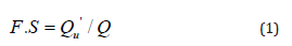
The factor of safety (FS) of pile foundation is defined as the ratio of the imposed Load on the pile to the mobilized bearing capacity of the soil (equal to the sum of base resistance and skin resistance). i.e,
For the recommended pile under consideration, the Ultimate
Carrying Capacity, Qu, can be assessed using equation (1) above as
follows: -
For a Steel Pipe diameter of 400mm and a Factor of Safety (F.S)
of 3.0.
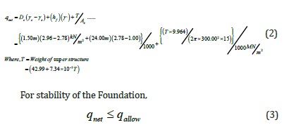
Imposed load on the piles = Wt. of super-structure + Wt. of substructural
pad overlying the pile cap.
Assuming the total load of the superstructure, = (T) Tons, and
Area of each Pier = (As), then the Total imposed Net soil pressure
(qnet) is:

Summary of Soil Profiles
Within the Project site tested, there are five (5) basic types of
soil profiles namely:
i. Brownish Clay Layer (CL) – Top Soil
ii. Greyish Organic silty Clays (OL)
iii. Yellowish Clayey Sands (SC )
iv. Greyish Silty- Sands (SM) and
v. Well-graded Gravelly-Sands (SW)
These basic soil types are found in these three Zones used in this study, as shown in the Fence Diagrams of each Zone (Figures 5a, b and c). Table 7 is the summary of bearing capacity values from field SPT soundings. Table 8 is the consolidation, bearing and drainage characteristics of materials in the area while Table 9 is the summary of pile bearing capacities at different pile diameters in each zone. Table 10 shows the summary of results on soil liquefaction potentials at the Federal University site, Otuoke, Bayelsa State (Figures 5a, 5b,5c) (Tables 7-10).
Table:7Summary of Bearing Capacity Values from Field SPT Soundings.

Table:8Consolidation, Bearing and Drainage Characteristics of Materials in the Area.

Table:9Summary of Pile Bearing Capacities at Different Pile Diameters in Each Zone.

Table:10Summary of Results on Soil Liquefaction Potentials at the Federal University site, Otuoke, Bayelsa State.


Conclusion
The results of the study revealed soil properties at the various Zones of the University Complex and the Bearing Capacities of the Piles to maximum depths of 30.00 meters at different Pile diameters. At all intensities of Earthquake [M = 6.0; 7.50 and 8.25], there was little possibility of any liquefaction occurring in the area. This can be explained by the fact that the water table at site is about 3.00 meters below the ground surface. Most liquefaction occurs when the water table is near the ground surface.
On the basis of the computations carried out as revealed in this
study, the following recommendations are hereby made: -
1. The obtained value for the Bearing Capacity for Isolated
Footings to be used at the Project Site is about 195.35 +
1.1867B [kPa] where B = Width of the Structure to be built. For
a B = 5.00 meters, the Bearing Capacity has been found to be
201.284 kPa. The recommended depth of emplacement
1. of isolated footings is 1.50 meters. This value represents the
bearing capacity of the upper bearing lateritic clayey sands at
the project site.
2. The obtained value for the Bearing Capacity for Continuous
Strip Footings to be used at the Project Site is about 153.35
+ 1.483B [kPa] where B = Width of the Structure to be built.
For a B = 5.00 meters, the Bearing Capacity has been found
to be 160.76 kPa. The recommended depth of emplacement of
Continuous Strip Footings is 0.75 meters. This value represents
the bearing capacity of the upper bearing Lateritic Clays and
Silty-Clays at the project site.
3. The range of values obtained for the Bearing Capacity for Raft
Footings at the project site, based on the methods of Meyerhof
[8]; Terzaghi & Peck [10] and the conventional SPT Method is
between 76.55 and 208.86 kPa with an average of 122.85 kPa.
The recommended depth of emplacement of Raft Footings is
1.50 meters. This value represents the bearing capacity of the
upper bearing Lateritic Clays and Silty-Clays at the project site.
4. A value of qallowed = [14.4] + [(9.964T)/( B x L)] kN / m2 can
be used as the allowable Soil Pressure on the soil at the project
site, since this value should be less than the average value of
the allowable soil pressure (bearing capacity ), q(allow) of the
soils at site. [Note: B = breadth; L = Length of structures at site].
5. The computed settlement data for the project area indicate
that the Immediate Settlement values for the Project Site is
estimated to be about ri = 0.0000132(T)(B) (meters) , where T
= the Dead weight of the Buildings at site. This is the settlement
expected to take place during the construction phase of the
Buildings at the Project site.
6. The computed settlement data for the project area indicate
that the Long-Term Settlement value for the Buildings at the
Site is estimated to be about 0.000132 T + {(0.520) Log 10 (1
+0.01498 T)} (meters), where T = the estimated Dead Weight
of the Buildings. This is the settlement expected to take place
long after the construction phase of the buildings at the various
zones at the Project sites.
7. About 50% of the settlements must have taken place about
3.70 years after construction, while 90% of the settlement will
take place after about 15.728 years after the completion of the
Buildings at the University Complex.
8. Since the buildings at the university Campus may subjected
to Live Loads from the movements of different numbers of
students in a continuously day-to-day fashion over the years,
the potentials of the silty soils becoming liquefied as a result
of human traffic-induced vibration was also assessed during
this study, since this is a permanent structure for ages to come.
Soil dynamics analysis carried out indicates that there will
be no possibility of Soil Liquefaction at the site as a result of
vibration from the Gas Plant. This was found not to be possible
even though the groundwater table was found near the ground
surface because of the absence of totally silty soil beneath the
ground surface [13-16].
Acknowledgment
The authors greatly appreciate the support of colleagues in the Department of Geology, Rivers State University, Port Harcourt.
Conflict of Interest
No conflict of interest.
References
- Oke SA, Amadi AN (2008) An assessment of the geotechnical properties of the sub-soil of parts of Federal University of Technology, Minna, Gidan Kwano Campus, for foundation design and construction. Journal of Science, Education and Technology 1(2): 87-102
- Oke SA, Okeke OE, Amadi AN, Onoduku US (2009) Geotechnical properties of the sub-soil for designing shallow foundation in some selected parts of Chanchaga area, Minna, Nigeria.
- Amadi AN, Eze CJ, Igwe CO, Okunlola IA, Okoye NO (2012) Architect’s and geologist’s view on the causes of building failures in Nigeria. Modern Applied Science, 6 (6): 31-38.
- Ngah SA, Nwankwoala HO (2013) Evaluation of Geotechnical Properties of the Sub-soil for Shallow Foundation Design in Onne, Rivers State, Nigeria. The Journal of Engineering and Science 2 (11): 08-16
- Oghenero AE, Akpokodje EG, Tse AC (2014) Geotechnical Properties of Subsurface Soils in Warri, Western Niger Delta, Nigeria. Journal of Earth Sciences and Geotechnical Engineering 4(1): 89-102
- Etu-Efeotor JO, Akpokodje EG (1990) Aquifer systems of the Niger Delta. Journal of Mining Geology 26(2): 279-284.
- Short KC, Stauble AJ (1967) Outline of Geology of the Niger Delta. American Association of Geologists 5(51): 761-779.
- Meyerhof GG (1951) The Ultimate Bearing Capacity of Foundations. Geotechnique.
- Peck RB, Hanson WE, Thornburn TH (1973) Foundation Engineering 2nd Edition John Wiley and Sons p.514.
- Terzaghi K (1943) Theoretical Soil Mechanics. Wiley & Sons, New York, USA.
- Vickers B (1978) Laboratory Work in Soil Mechanics, Second Edition.
- 1990) British Standard Methods of Test for soils for Civil Engineering Purposes. B.S 1377: Part 2, 1990. Published by the British Standards Institution, pp. 8-200.
- Murthy VNS (1984) Soil Mechanics and Foundation Engineering, Dhanpart Rah and Sons, India.p.763.
- Reyment RA (1965) Aspects of Geology of Nigeria. University of Ibadan Press, Nigeria. P.133.
- Skempton AW, MacDonald DH (1956) The Allowable Settlement of Buildings, Proc. Inst. Of Civil Engineers, Part 3, 5, pp. 727-784.
- Tomlinson M J (1999) Foundation Design and Construction 6th Edition, Longman, pp.536.
-

This work is licensed under a Creative Commons Attribution-NonCommercial 4.0 International License.


