 Review Article
Assessment of the Quality of Rolled Steel Bars according to the Bekaert Criterion, used for Prestressed Concrete
Robert Kruzel*
Faculty of Civil Engineering, Czestochowa University of Technology, Akademicka 3, 42-201 Częstochowa, Poland
Robert Kruzel, Faculty of Civil Engineering, Czestochowa University of Technology, Akademicka 3, 42-201 Częstochowa, Poland
Received Date:April 04, 2024; Published Date:April 11, 2024
Abstract
This paper presents the results of tests on wire rod and high carbon wires used in prestressed concrete construction for acceptance according to the guidelines imposed by Bekaert and the generally accepted Betaert standards. For prestressed structures, such acceptance of wire rod is not yet used. However, worldwide, for some steel products made of wire rod, these standards are mandatory. In the construction industry, where prestressed or post-tensioned This paper presents an analysis of phenomena occurring in the production processes of steel wire rod and wires made of high-carbon steels and their influence on shaping the properties of wires after the manufacturing process. The genesis of this research stems from contemporary trends in the metallurgical industry which aim to optimise quality and intensify the production process. At present, the main direction of development and modernization of metallurgical plants is the implementation of technologies for high-speed production of wire rod and wires from high-carbon steels, used, among others, in the production of ropes, springs. used, among others, and for the widely discussed construction industry. The multi-parameter analysis of the problem included a theoretical analysis of the phenomena occurring in the manufacturing process of wire rod and wires, supported by experimental measurements and comprehensive studies of mechanical properties, technological, fatigue strength, structure, surface topography. The results obtained from the above-mentioned research made it possible to analyse the changes of properties in wire after the manufacturing process and to develop guidelines for modernisation of technology in industrial plants as well as a new approach to quality control of steel for the construction industry.
Keywords:Concrete string; ribbed bars; concrete cables
Introduction
The first patent for prestressing concrete with steel bars was obtained by P.H. Jackson of California in 1888, when the idea of prestressed concrete was then described as an innovative way of strengthening concrete structures. But technological considerations of obtaining cheap steel with high strength prevented the practical application of this idea to prestressing. For steel wire to be used in prestressed concrete or post-tensioned concrete structures, it must meet many requirements for high tensile strength and technological properties. The decisive influence on the quality of steel wire is the quality of wire rod. In general, it can be said that prestressed concrete is made up of steel strings (wires) that are tensioned before casting and released after the concrete has hardened [1]. In prestressed concrete (prestressed concrete), prestressing forces are transmitted due to the adhesion to the concrete of wires suitably shaped by waving or surface pressing. To increase the adhesion of the wires to the concrete in prestressed structures, ribbed bars [2,3] or wires twisted into strands or special ropes called prestressing ropes are often used. Similarly, “cableconcrete” is made, in which the whole reinforcement in the form of steel cable-cables and thick ribbed bars are mounted to previously poured concrete structures with prepared technological openings, where they are inserted, stretched and poured with concrete. In both methods, when the tension force is removed, the wires shrink while compressing the faces of the concrete elements [4]. These reinforcements in reinforced concrete structures basically have a passive role, i.e., they strengthen the concrete only after the load occurs. The subject of prestressed reinforcement, as well as safety and reliability of reinforced concrete structures, fits well into the category of sustainable development, because sustainable development is intergenerational solidarity consisting in finding such solutions which guarantee further growth and allow active inclusion of all social groups in development processes, at the same time giving them the opportunity to benefit from economic growth. It is worth remembering that sustainable development in the construction industry is to ensure a reasonable and successive increase in the standard of living - not only for the current, but above all future generations. Millions of years of the existence of evolving nature and the phenomena occurring in it, should be a lesson for us and a source of knowledge on the best solutions. In the long run, the synergy resulting from eco-development will certainly translate into optimal efficiency in every sphere of human activity [5-7].
That is why concretes are pre-stressed with high-strength high-carbon steels to reduce the use of natural building materials and at the same time to permanently reinforce modern structures. Compared to low alloy steels used for reinforcing bars, where the carbon content is up to 0.30%, prestressing steel has up to 0.95% carbon. The addition of carbon gives the steel high strength, but as the carbon content increases, so does the brittleness of the steel. Steels with strengths ranging from 1800 to 3000 MPa are used for prestressing. The most common strengths are around 1800 and 2000 MPa. A very important difference between high-carbon steels and low-alloy steels is the way bars and wires are produced. Reinforcing bars of low alloy steels are rolled with a diameter of 5.5 mm and then hardened using the Stelmor technology, which involves rapid and controlled cooling to obtain the appropriate properties. (It is here that the achievement of the appropriate mechanical properties of bars rolled in the Stelmor technology, through such selection of the conditions of multi-stage cooling by air and water spraying, allow to obtain in the carbon steel wire rod ferritic-perlitic structure in the entire cross-section of the bar Both the strength and hardness are equal at the cross-section of the wire rod, as well as along the entire length, in the coil rolled steel) [33]. A further reduction of the diameter of the wires to be compressed is achieved in the process of cold working by drawing, until the required diameter is obtained. The greater the number of drawing operations the greater the strength, but lower the ductility and limit strain at break [8-10].
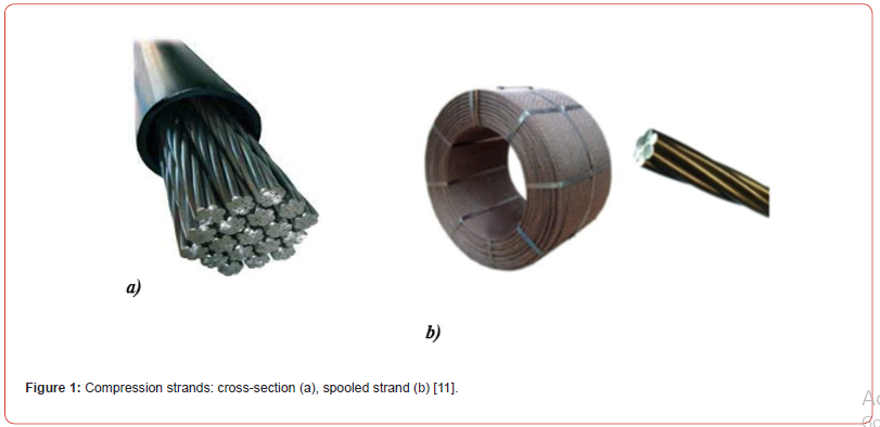
The prestressing force is introduced into the prestressed concrete element by means of prestressing tendons. The dominant type of tendon is a seven-wire steel strand (Figure 1a) [11]. Such strands are usually composed of seven round wires and have different diameters (7x2,5, 7x4, 7x5, 7x6 mm). In the application for cable concrete the 7x5 mm strands with outer diameter of about 16 mm are predominant. Such a strand is built from the central wire (king wire) and six outer wires braided on it. The outer wires are usually slightly smaller in diameter than the inner wire. The prestressing strands are produced in drawing plants and sold in coils of 3t weight (Figure 1b) [11].
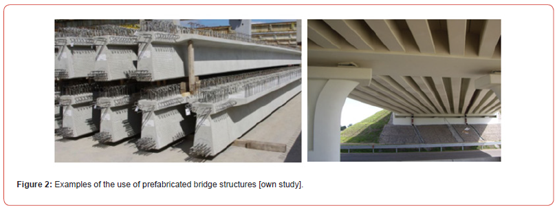
Prestressed structures, such as prestressed concrete or posttensioned concrete, are structures very often used as a reinforced concrete element into which, after it has been concreted and obtained the required strength, an additional system of forces has been introduced causing an initial state of stress. According to the idea of prestressed structures, this is a state of stress opposite to that which will occur under external loads. Both elements with tendons running internally (with and without adhesion) and those where the tendons run outside the structure are considered as post-tensioned elements. Prestressed concretes are very commonly used: from railroad sleepers, traction poles to bridges (Figure 2), and roof girders, nuclear reactor housings and airport runways [7,12,13].
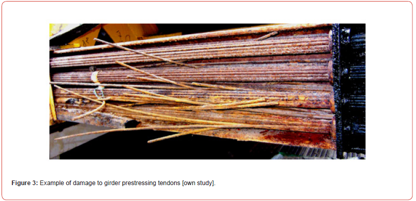
However, such structures require constant inspection and especially maintenance. The steel tendons prestressing the girders are subject to the occurrence of corrosion, and when the structure is loaded, damage to these tendons may occur, as shown in Figure 3. During repair works and removal of cable duct covers, one can often see foci of corrosion and find in many places missing anti-corrosion protection as well as corroded and torn-off cables - Figure 3. In view of such a serious situation, a decision should be made quickly to replace the existing tendons. Apparently, this was not the case with the now famous 2018 Morandi 14 bridge disaster in Genoa. Several causes were considered, primarily years of neglect in its maintenance, disregard for damage, and a design defect. The reality of the construction showed that replacing the tendons was in practice impossible: removing the bituminous mass is technically very difficult and labor intensive, and consequently uneconomical [8, 14-16].
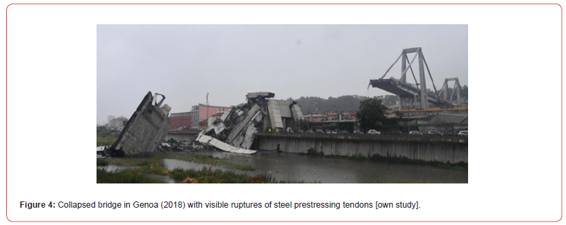
The reinforced concrete bridge in Genoa (Italy), using prestressed elements, has been under constant maintenance in recent years due to half a century of construction and the dynamic loads from traffic unimaginable in the 1960s on the A10 freeway. It had already been estimated for some years that the costs of ongoing repairs would make them uneconomic compared to a thorough rebuilding of the entire structure. In addition to the costs, there was also the problem of switching off the structure, for which so far there have been no detours in the Ligurian region, and indeed nowhere south of the Alps, capable of carrying comparable traffic. In addition to the approach viaducts, the central part of the bridge had three similar spans in the shape of superimposed letters “A” and “V” with pylons of about 90m in height, to which a bridge slab was suspended with two cantilevers at the ends (at a height of about 45m). Each such set with connectors freely suspended between them was 210m long. The western element collapsed: the one over the river and railroad line, fortunately because there were no residential houses under it. The suspensions - 34 on each segment, were most likely made of prestressed concrete and, as one might expect, probably corroded the anchorages of the prestressing rods or cables at the highest force-carrying points of attachment to the cantilevered end of the running board as shown in Figure 3, and possibly at the gables as well. The vibration from the wind, a pulse of lightning that supposedly struck the pylon, triggered the disaster. It is also worth noting here that the opposite set of analogous three segments had steel ties attached to the 4 tensile suspension members along their entire length, and the middle pylon clearly had something reinforced at the gables. These other two twin-span sets, structurally independent of the collapsed one, were not damaged except for the expansion joint of the collapsed connector over the railroad
Cathodic Protection of Steel
There is a new - simple cathodic method for electrochemical corrosion, in which there is no need for an external power source, so this method can be used in objects exposed to cyclic contact with water. Cathodic protection of steel involves the creation of a galvanic cell between the reinforcing steel and the zinc sacrificial, with a corrosion potential more negative than that of the steel [9,17]. The water solution in the pores of the concrete plays the role of the electrolyte. In the cell thus formed, current flows from the protector to the protected metal, i.e. the reinforcing steel. Due to the fact that in the created cell the protector becomes the anode and the reinforcing steel becomes the cathode, the oxidation (corrosion) reaction takes place on the anode, and the metal is permanently protected. The cathodic method, allows the protection of separated zones and begins to be effective already after the protector is connected to the rebar and after grouting, which creates a comprehensive system of corrosion protection for reinforcing steel and allows to maintain the longest possible service life of the entire structure [11,18].
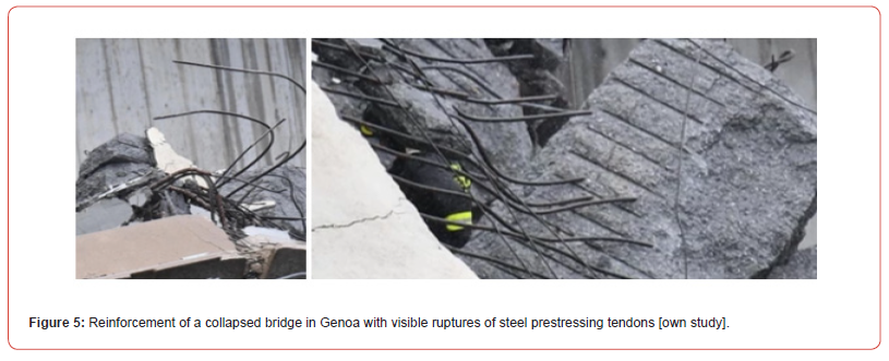
However, it is still unclear why a section of the giant 250-meterlong structure collapsed just before noon on August 14, 2018, during a violent storm. The collapsed bridge is shown in photos Figures 4 & 5. Only hypotheses continue to be pointed out, such as an error in design, negligent maintenance, disregard for progressive corrosion, and increasing overload over the years due to heavy traffic on this most important artery in the city. Analyses of the causes of disasters of this type show that there was no regular checking of the condition of the building for the so-called resonance frequencies. Then we have fatigue of materials, rusting of concrete and finally waterlogging of the structure, foundations, which could also take place in this case due to rainfall. The following paper presents the results of testing high-carbon wire rod used in prestressed concrete construction for acceptance according to the guidelines imposed by Bekaert and the generally accepted Betaert standards [18,19]. Such acceptance of wire rod is not yet used in the construction industry. However, for some steel products made of wire rod, these standards are mandatory, e.g. for the production of reinforcement in the form of steel cord for the reinforcement of car tires. In the construction industry where prestressed or post-tensioned prestressed concrete is required these tests should be, in the opinion of the authors of this paper, even obligatory.
Modern trends in manufacturing processes of steel wires
Medium and high carbon steel wires are widely used in industry, e.g. for steel cables, springs, cord, for prestressing concrete structures, etc. Wire intended for the above-mentioned products must have high strength and technological properties, as well as high fatigue life [20,21]. In recent years, a lot of work has been done to improve the mechanical and technological properties of steel wires by modifying the drawing conditions. Following the development of the drawing industry in recent years, one can see a significant development of drawing technology towards improvement of process efficiency and quality of drawn wires. Intensification of the drawing process changes the deformation conditions, forcing manufacturers to apply new technological solutions for surface treatment, lubrication, and drawing process, e.g. by using modified conventional and hydrodynamic drawing dies. Therefore, it is important to know the influence of new high-speed multistage drawing technologies on drawing process parameters and properties of steel wires, e.g. for the construction of such responsible structures as bridges and viaducts.
In the drawing process of low carbon steel wires, the preliminary annealing of the wire rod is omitted. The wire rod undergoes only surface treatment, which includes pickling, acid neutralisation, application of lubricating layers and drying of the wire rod. The prepared wire rod is then drawn to the specified final size. Depending on the purpose of the wire and its diameter, an additional intermediate annealing of the wire is carried out, usually in a protective atmosphere. Due to the high costs associated with pickling, mechanical descaling methods, e.g. wire rod bending and cleaning with brushes, are becoming more and more common worldwide. Mechanical descaling equipment is installed directly in front of the drawing mill. The omission of pickling and underreaming in the drawing process, by using mechanical descaling methods and wire annealing in a protective atmosphere, has significantly reduced the cost of steel wire manufacturing. But the quality of the outer surface of the wires and the defects that occur have a significant impact on the subsequent failure of the wires in prestressed structures.
In order to improve the efficiency of the drawing process in large plants, modern multistage drawing machines and cassettes, which are an extension of roller drawing dies, are installed, allowing the realization of large degrees of deformation at significantly higher drawing speeds. At present, intermediate recrystallization annealing operations are usually omitted in the production of low carbon steel wires [22-24]. The available scientific literature also shows that drawing technology significantly affects the microstructural changes in the drawing process of high carbon perlitic steel wires. Analyzing the high-speed drawing process, the influence of the aging process on the structural changes and properties of the drawn wires cannot be overlooked either. Numerous studies have unequivocally shown that ageing processes are among the main factors responsible for decreasing wire ductility and increasing their yield and tensile strength. Ageing processes in the drawing process occur as a function of time and wire temperature. Moreover, these phenomena take place when wires are stored at ambient temperature. Therefore, very high temperatures of wire drawn at high speeds as well as a high degree of their strengthening may cause the occurrence of dynamic ageing phenomena which deteriorate the plastic as well as technological properties of wire.
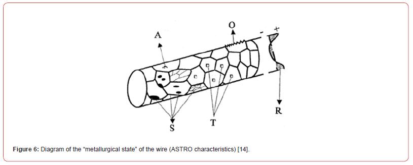
Therefore, it seems necessary to carry out comprehensive structural investigations in wires after drawing process. Investigations of the effect of drawing speed on the previously mentioned structural changes will be carried out according to the ASTRO characteristic proposed by E. Aernoudt. On the other hand, the research on the quality of wire rod according to the guidelines of comprehensive Bekaertˊan evaluation used in the production of prestressed concrete. Figure 6 shows a diagram of the “metallurgical state” of a wire called ASTRO characterization. According to E. Aernoudt [14], a complete ASTRO characterization includes: chemical analysis of the steel (A), structure (S), texture (T), self-stress (R), and surface roughness (O) [14]. Analyzing these issues, one should also pay attention to the fact that it is the technical progress that forces manufacturers of wire and wire products to continuously improve the technology of their production. An additional factor stimulating the development of the drawing industry are economic reasons. In order to increase competitiveness in the global market modern wire factories are forced to seek new solutions to increase their productivity and reduce production costs while maintaining high quality of drawn products.
Currently, the main direction of development and modernization of drawing plants is the implementation of technology for highspeed drawing of high-carbon steel wires. The main obstacle in the implementation of this technology is the intense heating of the surface layer of the wire, which leads to the deterioration of lubrication conditions, rapid wear of drawing dies and a decrease in wire properties below the applicable industry standards. Drawing plants have partially solved this problem by using phosphate underlubrication layers, salt lubricant carriers and rotary drawing dies on the first drawing stage in the drawing process of high carbon steel wires. Summarizing the state of research to date on the effect of high-speed drawing on the properties of high-carbon steel wires, it should be stated that this problem has not been fully clarified. Fragmentary or partial solutions to the issues of highspeed multistage drawing, however, are limited only to the analysis of the high-speed drawing process in conventional drawing dies. These studies show that when wire is drawn at speeds above 15 m/s, intense heating of the wire surface layer occurs, which can lead to a significant deterioration of lubrication conditions and a reduction in the quality of the drawn products below current industry standards. It has been shown that borax grease layers and typical drawing lubricants do not guarantee adequate lubrication when drawing wires at speeds above 15 m/s [25,26].
Improving lubrication conditions in the high-speed wire drawing process for prestressed concrete
The improvement of lubrication conditions in the drawing process is also possible by using hydrodynamic drawing dies in which the deformation is realized through the lubricant layer with significantly lower friction COE in comparison to drawing in conventional drawing dies. However, it was shown that the use of hydrodynamic drawing dies positively influences the changes of structure and properties of drawn wires. However, these investigations were performed at very low drawing velocities, usually not exceeding 5 m/s. An increase in drawing speed in the range from 5 to 25 m/s, while maintaining good lubricating conditions manifested by a sufficient amount of grease on the wire does not cause a significant decrease in wire properties. However, an increase in drawing speed above 25 m/s causes a significant deterioration of lubrication conditions, which increases friction and may lead to accelerated wear of conventional drawing dies. The occurrence of surface delamination in high-carbon steel wires drawn in conventional drawing dies at high drawing speeds, of the order of 25 m/s, is associated with their higher strain irregularity, reduction of plastic properties, decrease in the orientation of cementite platelets, and increase in the degree of their fragmentation.
An increase in drawing speed causes an increase in pressure in the deformation zone of the hydrodynamic drawing die, which acting on the wire surface results in its smoothing and in extreme conditions may lead to a decrease in wire diameter. At high drawing speeds, in the order of 20÷30 m/s, the mechanism of wire properties shaping results from the interaction of the main parameters differentiating the conventional and hydrodynamic drawing processes such as friction, counter drawing, lubricant viscosity and pressure, deformation temperature. It means that wire properties after hydrodynamic drawing not always and not all can be better than after conventional drawing. Analyzing the phenomena occurring of multistage drawing processes at high speeds of high carbon steel wires in conventional and hydrodynamic drawing machines, as well as the analysis of the effects of these phenomena on the properties of drawing wires intended for steel prestressing tendons in precast concrete, makes it necessary to search for new solutions in order to improve the quality and increase the effectiveness of drawing processes [27,28].
Intensification of the drawing process and sustainability
The intensification of the drawing process can be achieved by increasing the size of individual crumples and by increasing the drawing speed. At present, due to the fact that as a result of significant technical development multistage drawing machines are available on the market, allowing the realization of the dry drawing process in 20 strings with the total crushing exceeding 95%, the main factor enabling the increase in productivity is the drawing speed, where it can be stated that the high drawing speed causes intense heating of the wire surface layer, which leads to worsening of lubrication conditions and properties of the drawn wires. This forces manufacturers to modify existing drawing technologies for high carbon steel wires. According to the typical technology for manufacturing high-carbon steel wires for drawing ropes, wire rod after patenting undergoes a surface treatment, which includes: etching, washing, boraxing and drying of wire rod. Material prepared this way is drawn on multistage drawing machines, so called straight drawing machines with the speed of 15÷20m/s, with the use of calcium, sodium or calciumsodium soaps. This technology does not guarantee good lubrication conditions, therefore companies manufacturing drawing lubricants were forced to develop new greases which are more resistant to high temperatures.
Bad lubrication conditions during drawing at high speeds in the traditional drawing technology were related to the borax lubricating layers, which did not guarantee the absorption and maintenance of a sufficiently large amount of lubricant on the drawing wire surface during the drawing process. Therefore, the borax lubricating layers have been replaced by phosphate layers, which enables a significant improvement of lubricating conditions and mechanical-technological properties of wires. Currently, during the phosphating process, wires are additionally coated with zinc salts of phosphoric acid. As a consequence, a layer of fine crystals, known in the literature as “salt lubricant carriers”, is formed on the surface of the wire rod. The fine salt crystals on the surface of the wire rod increase its porosity and adhesion of the coating to the metal surface. This allows more lubricant to be taken up during the drawing process, which results in a decrease in the temperature of the surface layer of the wire, allowing the drawing speed to be increased. The final stage of the modernization of the high-speed drawing line for steel wires is the installation of a rotary drawing die on the first drawing stage, which causes an improvement in lubrication conditions and a decrease in drawing stress in the drawing process. Due to the problems with cooling rotary drawing dies during drawing in industrial conditions the rotational speed of such drawing dies does not usually exceed 25rpm.
Coupled element and prestressed concrete used in bridge structures
A post-tensioned element is a reinforced concrete element into which, after it has been concreted and obtained the required strength, an additional system of forces has been introduced causing an initial state of stress. According to the idea of prestressed structures, it is a state of stress opposite to that which will appear under the influence of external loads. Both elements with tendons running internally (with and without adhesion) and those where the tendons run outside the structure are considered as post-tensioned elements. Although different types of non-metallic tendons (carbon fibers, aramid, glass ... etc.) are still being tested and used in the world, 99% of prestressed structures are made using steel cables or rods, wires. Steel wire ropes for prestressed structures are a product of wires, and their use in technology has been known for over 100 years. The reliability of ropes and their fatigue life largely depends on the properties of the wires from which they are made.
The continuous technological progress of steel melting and casting processes, wire rod rolling, descaling, wire heat treatment, and above all, the improvement of drawing conditions, especially on the basis of new methods of theoretical analysis of the process, makes it possible to obtain wires from high-carbon steels with increasingly better mechanical and technical properties and higher fatigue strength. Wire rope for prestressed structures is a loadbearing element of complex construction, whose main components are wires, strands, cores and lubricants. The technological process of wire rope for prestressed structures is complex and laborintensive. It can be divided into three stages: drawing the wires, making the strands and cores and winding the strands and core into a ready rope.
High-carbon steel wires intended for the production of ropes for prestressed structures, with 0,60 to 0,95% carbon content, should have high tensile strength and, at the same time, very good plastic properties and high abrasion resistance. In addition, the wires must show high suitability for working in the complex state of alternating stresses occurring in ropes for prestressed structures. In the working rope in a prestressed construction, the wire is subjected to cyclically alternating tension, bending, torsion and considerable lateral pressures, which causes its fatigue wear and cracking. Progressive fatigue wear of rope for prestressed structures is caused by changes in its component parts, i.e. wire and core. Measurable symptoms of fatigue wear of rope in prestressed structures are cracking of wires and elongation of the working rope.
Fatigue life of steel cables in prestressed structures
Papers published so far concerning fatigue life of prestressed
ropes show that the increase in number of wire cracks until the rope
breaks is influenced not only by operating conditions but also by
the construction of the rope for prestressed structures, technology
and quality of its manufacturing and, most of all, properties of
wires used for its manufacturing. The production of wires for ropes
for prestressed structures consists of a number of technological
operations. Their number depends on the type and quality of highcarbon
steel wire rod, the desired final diameter and the planned
mechanical and technological properties. In the production process
of round wires for prestressed structures, the basic technological
operations include:
a. surface treatment (removal of scale, application of lubricating
layers),
b. cold plastic processing (multistage drawing),
c. heat treatment (for high-carbon steels - patenting).
In the process of drawing wires for ropes for prestressed structures, these operations can be repeated many times, and each of them affects the final properties of the wire. As far as the operations of wire surface preparation for drawing and heat treatment are sufficiently developed and their repeatability depends on equipment and “technical culture” in a particular drawing plant, the relations between wire properties and drawing process conditions are not fully understood. In the drawing process there is a number of technological difficulties connected with obtaining the required dimensional tolerances, surface quality and obtaining the adequate mechanical and technical properties of wire. Moreover, the wire properties are influenced by the way of its plastic deformation, change in the material strengthening, the effect of drawing stresses and self-stresses in connection with the change in the structure, texture and state of the surface layer of drawn wires.
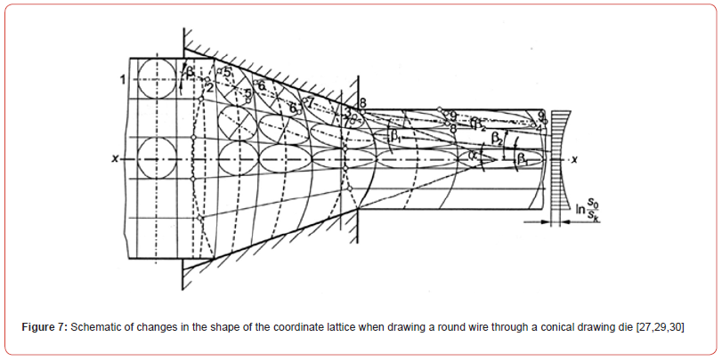
A lot of theoretical and experimental work has been done on the deformation inhomogeneity and the relationship between the parameters of the drawing process and the strain intensity distribution. Based on this work, some regularities governing this process can be identified. Different strain intensity across the cross-section of the drawn material results in non-uniform wire properties, related to the occurrence of differences in the structural structure, texture and stress distribution, as well as the geometric structure of the wire surface layer. On the other hand, the conical shape of the deformation zone, friction at the metal-drawing dies contact surface and the increase in the material length with a uniaxial decrease in its diameter make the deformation in the individual layers of the material, from the axis to its surface, non-uniform. The nature of the flow of the metal through the conical tractor and the changes in the shape and dimensions of the rectangular coordinate grid, plotted on the longitudinal section passing through the wire axis of symmetry, is shown in Figure 7 [27,29,30].
Friction during wire drawing has an influence on the temperature rise of the wire. The heat release during cold drawing is due to friction and plastic deformation work. Research indicates that about 10% of the heat is due to friction, while the remaining 90% is due to plastic deformation. The heat related to plastic deformation work causes an almost uniform increase in temperature across the cross-section of the drawn product, while the heat related to friction increases the temperature of the metal surface layer. Hence, the highest temperature in the surface layer occurs just after the deformed wire leaves the drawing die. After some time, the temperature is equalized between the surface and the wire axis due to heat conduction.
Authors’ Study on Steel Materials for Prestressed Structures
In the following work, quality testing of rolled steel in the form of wire rod and drawn steel in the form of steel wire was performed based on a niche and little-known method developed for cord wire intended for reinforcement of automobile tires, a method that is not used for any other purpose of steel wire. Bekaert has developed just such a comprehensive method for evaluating wire rod, in which various characteristics are assigned points (penalties). The technical specifications for wire rod define the chemical composition and mechanical properties and require the wire rod manufacturer to perform additional tests, such as metallographic testing, determination of surface quality and dimensional uniformity of the wire rod. Metallographic testing includes evaluation of perlite microstructure, phosphate bands, segregation, decarburization and non-metallic inclusions. Surfaces are examined for defects such as scratches, rerolls, seams and pitting. During wire rod examination, the severity of metallographic features and surface defects is evaluated and penalty points are assigned based on the level or size of the defect. The sum of penalty points reflects the quality of a given heat of wire rod steel and is represented by the wire rod quality index (KJ) and the wire rod cleanliness index, SJ. The wire rod quality index, KJ, is determined by penalty points for metallographic examination of samples from twelve (12) individual coils (KJ = 100 - penalty points). The wire rod cleanliness index, SJ, shall be determined by penalty points for surface quality of samples from twelve (12) individual coils (SJ = 100 - penalty points). The wire rod quality index, KJ, and the steel cleanliness index, SJ, are included in the Certificate of Steel Heat Analysis (COA) or the wire rod shipping document. Under the Bekaert system for quality wire rod, surface cracks less than 0.15 mm are not penalized.
Non-metallic inclusions in wire rod are determined by microscopic examination (100X-200X) of several fields in samples from twelve different coils. Both frequency (number of inclusions) and thickness are recorded. The evaluation of inclusion frequency is based on the Swedish Jernkontoret method (ASTM E-45). The thickness of inclusions, or more precisely the ratio of length (l) to thickness (t), reflects the deformability of non-metallic inclusions. Inclusions with l/t>3 are considered deformable. Penalties for nonmetallic inclusions include scoring for both frequency and thickness. Complete results of wire rod heating tests are included in the acceptance certificate provided to the wire manufacturer. The authors’ own research was conducted using high-carbon steel wire rod from a Czech metallurgical plant with the following chemical composition shown in the Table 1, was used for the tests. In the authors’ own research, wire rod a nominal of diameter 5.5 mm which, as stated after a review of the literature in this field, and from the above analysis of steel quality, must be of good quality and intended for concrete strands and must not show any surface defects, especially in the form of collapses, cracks or fractures. Surface defects may cause non-uniform texturing during drawing or cold rolling and significantly reduce the mechanical properties of the material (Table 1).
Table 1:Chemical composition of steel for testing (Metallurgical attestation).

The structure of wire products includes both curved and straight sections, and only curved sections, as well as various types of tendons, prestressed and post-tensioned concrete used in reinforced and prestressed concrete structures. In the process of manufacturing various products from wire, the starting material of wire coils is usually straightened first and then transformed into various products. Even in cases where the product to be shaped has the same curvature along its entire length, it is generally the case that the initial straightening is carried out first and only then does the actual shaping of the product take place. It is connected with the aspiration to obtain as equal conditions as possible for the process of shaping the given product. It should be remembered that seemingly uniform conditions under which the drawing process takes place, in fact change within certain limits, and an external symptom of the changeability of these conditions is the fluctuation of the wire curvature after leaving the drawing die or after being wound onto the drawing machine drum. In order to stabilize the operating conditions of various machines, the wire is preliminarily straightened. The wire straightening consists in giving it such a curve during the active phase of the process that after removing the external load the material is straight. The unloading of the material leads to a partial return to the original curvature. However, for the complete straightening it is necessary to give the material the opposite curvature in relation to the original one, because then the material will be straightened after the unloading.
Analysis of factors influencing wire cracking during operation in prestressed structures
The performed analysis of the state of residual stresses in drawn wires showed that in the surface layers of the wire on the side of the drum tensile stresses remain after the drawing process, while on the opposite side, depending on the drawing conditions, tensile or compressive stresses may occur [31,32]. During straightening, the residual stresses are superimposed on the active stresses, whereby on the side of the drum conventionally referred to as the inner side, where tensile residual stresses were present after the drawing process, the active stresses are also tensile. In this situation, plasticization of the material begins on the inner side. In order to obtain a straight wire, it is indispensable to bend the wire in the direction opposite to the original curvature, since the stress relief of the wire is related to the tendency to return to the state before deformation. During straightening, plasticization can also occur on the outer side. Drawing the wire at high strain and on small diameter drawing machines promotes the occurrence of two plastic zones. Apart from the chemical composition, the purity of the steel plays an important role. It was found that non-metallic inclusions decrease the fatigue resistance of prestressed concrete. The main reason for this is that in very thin strings, under load, concentrations of stresses form around the inclusion which leads to local cracks and, as a result, wire breaks. Excessive content of sulfur, phosphorus, copper, gases and other harmful admixtures in steel also reduces fatigue resistance. As a result, special types of steels were developed for the production of strings in construction: with a minimum of non-metallic inclusions, without aluminum with a content of P and S not more than 0.030%, while the content of Cr, Ni and Cu not more than 0.05% of each of these components. This steel is characterized by a 40-50% lower saturation with gases such as oxygen, nitrogen and hydrogen. The wire rod, with a suitably prepared surface for cold-drawing, is pickled in hydrochloric acid and, after rinsing with water, a primer is applied, which may be borax, lime or phosphate. The final treatment is drying [33].
Main study. Quality assessment of steel wire rod used for prestressed structures, using the Bekaert method
In prestressed structures worldwide, there is a lack of testing for the steels used in the form of wire rod and rope, which could improve the reliability of their use in such responsible structures as bridges. A comprehensive method has been developed at Bekaert (Belgium) for the assessment of wire rod used in car tires. It seems that this method, which qualifies various properties of wire rod in the form of penalty points, could be mandatorily applied to the assessment of wire rod, from which wires will be produced, for prestressed structures such as prestressed concrete. The technical conditions of this method of wire rod quality assessment, in addition to assessing the chemical composition and its mechanical properties, force the wire rod producer to carry out additional tests, such as: metallographic tests, determination of surface defects, determination of the ovality of the wire rod. Within the scope of metallographic tests conducted, band structure, segregation and inclusions are evaluated. During the examination of the surface, defects in the form of scratches and cracks are taken into account. During the examination of metallographic features and surface defects of the wire rod, an assessment of these defects is made. The method also includes a penalty point system, which enables the assessment of a melt or batch of wire rod by determining the wire rod quality index KJ and its purity grade SJ. The wire rod quality index KJ is determined on the basis of penalty points after strip structures, segregations, cracks and inclusions have been determined on 12 samples. The calculation method of wire rod quality index and steel cleanliness index - SJ, is as follows: KJ (SJ) = 100 minus the sum of penalty points. In the authors’ own research, wire samples and their structures were analyzed for 10 samples, and the results in the form of penalty points for strand structure are summarized in Table 2 and penalty points for segregation in Table 3.
Table 2:Criteria of penalty points for band structures.
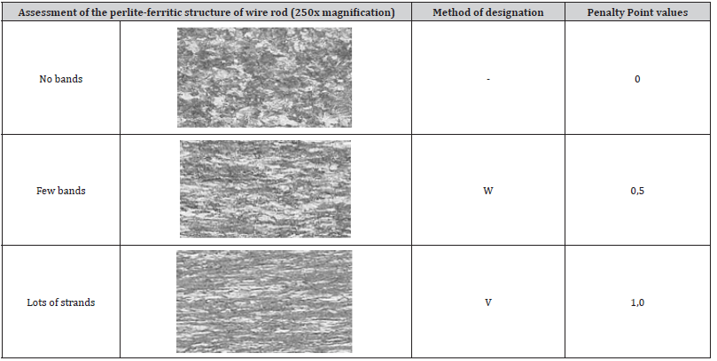
Table 3:Criteria for segregation points.

Analysis of the surface quality of wires after drawing along with their surface topography
In the drawing process, as the total crumple increases (after successive draws), more and more striations of the structure start to appear in the whole volume of the deformed material. With the increase of the total crease there is also an increase in the intensity of the fibrous texture <110>, which becomes the dominant texture in the final wire. For special applications of wire rod, they are always measured. In our study, the authors analyzed the surface quality of wires after drawing and their surface topography, according to the Bekaert penalty point system. Cracks are marked from a length of 0.15 mm. For special applications of wire rod, e.g. for prestressed structures, according to the authors, they should always be measured. The values of these penalty points, caused by surface defects, are illustrated from the surface measurements of the wire rod and are presented numerically in Table 4 & Figure 8.
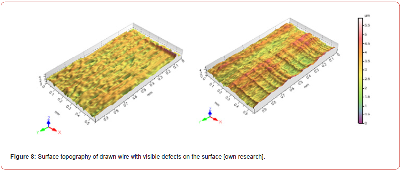
Table 4:Penalty points due to surface defects.

Quantitative analysis of non-metallic inclusions for tested steel wire rod
In our study, non-metallic inclusions, divided into hard and nonhard, were also performed for the steel under study and determined using a microscope on the wire specimens, which were taken at the most contaminated area of each specimen, according to the number and thickness of the inclusions. The tests presented are based on the Swedish Jemkontoret method (according to ASTME45). The penalty point value for the test sample also depends on the degree of deformation of the inclusions. Table 5 summarizes the penalty point values for inclusions in wire rod made of low carbon (mild) steel and wire rod made of medium and high carbon (hard) steel. Penalty points for inclusion thickness were calculated by observing the surface of each sample under a microscope and then selecting the most contaminated areas, as shown in the following images of the structures (Figure 9 & Table 5). The number of penalty points for inclusions, for the tested steel samples is summarized in Table 6.
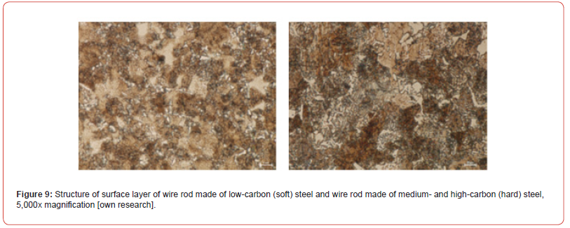
Table 5:Penalty points depending on degree of incisal deformation.
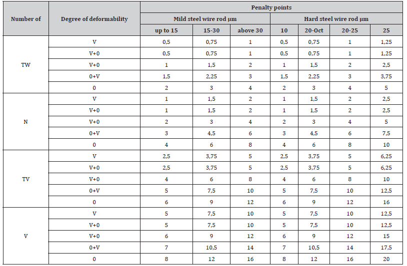
Table 6:Penalty points for inclusions.

TW: very small; N: normal; TV: quite large; V: large
Examination of wire rod ovality with analysis of shape in cross-section
Ovality, which is the difference between the maximum and minimum dimensions of diameters measured on the same section, is rated as poor or significant (Table 7). In industrial practice, ovality is expressed as a percentage of 100 coils (Figure 10).
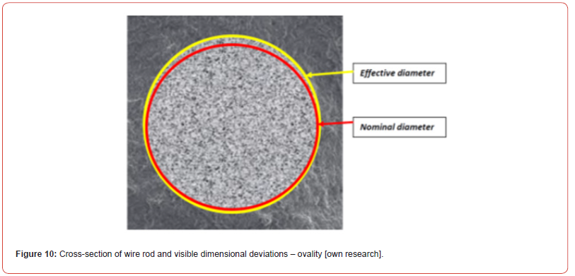
Table 7:The dependence of rolling ovals on its diameter.

Metallographic analysis of inclusions in steel, including sulphides and non-metallic inclusions including oxides and silicates
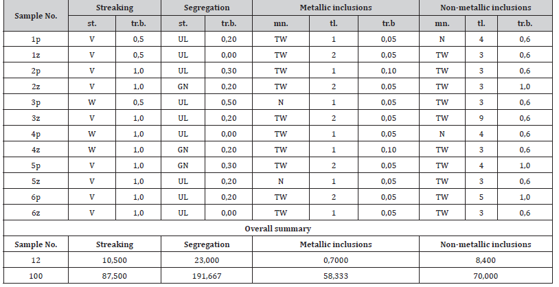
In addition to chemical analysis, metallographic analysis was performed on the wire sample. The results of this analysis are listed in Tables 8 and 9. Mechanical inclusions include sulfides and silicates (≥ 3 μm in size). Non-metallic inclusions include point oxides and silicates (thickness < 3 μm). The maximum allowable thickness of non-metallic inclusions is 15 μm. as illustrated by the following structures (Figure 11 & Tables 8,9):
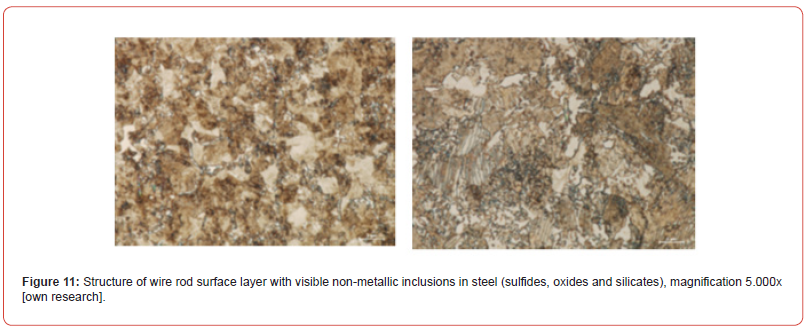
Table 8:Metalcutting by Bekaert.
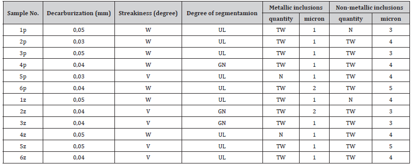
Table 9:Quality rating by GA – 03 – 02.
Summary
Summarizing the above studies, it is important to state that for prestressed structures used in construction for bridges, viaducts, etc. where significant amounts of rolled steel in the form of wire rod and drawn steel in the form of steel wires are used, no attention is paid to the very important issue of its defectiveness, which can lead to disasters after a long period of operation, as it happened in 2018 in Italy in Genoa. Based on the Bekaert method of examining the finished product such as wires and wire rod, which involves assigning penalty points to various steel characteristics and their defects. Characteristics such as metallographic examination, determination of surface quality and dimensional uniformity of wire rod, which include evaluation of perlitic microstructure, phosphorus bands, segregation, decarburization and non-metallic inclusions have been studied. Surface examinations analyze the presence of defects such as scratches, rerolls, seams and pitting. During wire rod examination, the severity of metallographic features and surface defects was evaluated and penalty points were assigned according to the level or size of the defect. The sum of the penalty points reflecting the quality of the individual steel features was subtracted from 100 giving the result = KJ. The minimum KJ value should be 72 (quality index (KJ), according to Bekaert guidelines). Then, all results above this value mean that the wire rod meets the requirements of manufacturers of steel wire for prestressed concrete and prestressed concrete. As can be seen from the above tests: the tested wire rod has a final quality rating according to Bekaert of KJ = 78.40. This means that it is of very high quality and is successfully suitable for such a responsible product as bridge concrete wire and for use in prestressed concrete. Surface defects are not specified here because none were found. The chemical and metallographic properties of the material are judged to be very good and comparable to those of the world’s major manufacturers of wire rod for prestressed concrete and prestressed bridge concrete. The wire rod has a final quality grade according to Bekaert, which will be: KJ = 78.40. This means that it is of very good quality and is successfully suitable for such a responsible product as prestressed concrete wire rod and for use in prestressed concrete. However, this is not always the case. It should be noted here that such testing is not performed as standard by prestressed concrete manufacturers, which can have disastrous consequences for such structures in the future, where erosion of concrete and steel reinforcement having hidden defects can cause a disaster similar to the one described in the above article. May such a disaster in which people die never happen again.
References
- Adamczyk J, Burdek M, Suliga M, Pilarczyk JW (2012) Wpływ kształtu ciągadła na chropowatość powierzchni drutów ze stali wysokowęglowej. Hutnik – Wiadomości Hutnicze (12): 892-895.
- Adamczyk J, Suliga M, Pilarczyk JW, Krnać J (2012) The analysis of influence of the shape of conical die on properties of high carbon steel wires. Steel Research International, Special Edition, Proceedings of the 14th International Conference on Metal Forming, METAL FORMING 2012, Akademia Górniczo-Hutnicza, Kraków, Poland, 16-19 pp. 499-502.
- Adamczyk J, Suliga M, Pilarczyk JW, Krnać J, Burdek M (2013) Wpływ geometrii ciągadła na wytrzymałość zmęczeniową drutów ze stali. Hutnik - Wiadomości Hutnicze 1(2): 7-9.
- Adamczyk J, Suliga M, Pilarczyk JW, Burdek M (2012) The influence of die approach and bearing part of die on mechanical-technological properties of high carbon steel wires. Archives of Metallurgy and Materials 57: 1105-1110.
- Avitzur B (1976) The application of hydrodynamic lubrication in wire drawing and extrusion. Wire Industry pp. 74-79.
- Enghag P (2010) Steel Wire Technology. Repro Örebro Universilty, Örebro, Sweden.
- Golis B, Pilarczyk JW, Dyja H, Błażejewski Z, Muskalski Z (2010) Effort and fracture of wire in the drawing process. Wire Journal International pp. 104-111.
- Blikharskyy Y, Selejdak J (2021) Influence of the percentage of reinforcement damage on the bearing capacity of RC beams, Construction of Optimized Energy Potential (CoOEP) 10(1): 145-150.
- Jarl M, Axelsson F (2002) Wear of die, measured and calculated by the process control system in a drawing machine, Proceedings WAI International Technical Conference, Monterrey, N.L. Mexico pp. 143-151.
- Kruzel R, Suliga M (2013) The effect of multiple bending of wire on the residual stresses of high carbon steel wires. Metalurgija 52(1): 93-95.
- Pilarczyk JW (2006) Selected issues of drawing wires from high-carbon steel. Monographs series 115, Częstochowa University of Technology Publishing House. Częstochowa, Poland.
- Kruzel R, Suliga M (2012) The influence of conventional and hydrodynamic die rotational speed on drawing process and properties of high carbon steel wires. Steel Research International, Special Edition, Proceedings of the 14th International Conference on Metal Forming, METAL FORMING 2012, Akademia Górniczo-Hutnicza, Kraków, Poland pp. 519-522.
- Milenin A, Dyja H, Muskalski Z (2003) Finite element modeling of the influence of changes in the drawing direction between passes on the final distribution of strains in the wire rod cross-section. FIMM 2003 conference, "Physical and mathematical modeling of plastic forming processes", Publishing House of the Warsaw University of Technology, Scientific Works, Mechanics, Warsaw (201).
- Aernoudt EAD (2009) Drawing induced structural and mechanical anisotropy. Mordica Memorial Lecture, WAI’s 79th Annual Convention.
- Avitzur B (1983) Handbook of Metal-Forming Processes. A Wiley – Interscience publication. John Wiley & Sons, New York, USA.
- Gillström P, Jarl M (2007) Wear of die after drawing of pickled or reverse bent wire rod. Wear 262: 858-867.
- Sang-Kon Lee, Won-Ho Hwang, Dae-Cheol Ko, Byung-Min Kim, Woo-Sik Ko (2007) Pass schedule of wet-wire drawing process with ultra-high speed for tire steel cord. Key Engineering Materials 340(341): 683-688.
- Walentek A (2007) Quantitative characterization of microstructure of two-phase materials: the case of pearlite. Katholieke Universiteit Leuven, Leuven, Belgium (Doctoral thesis).
- Suliga M, Kruzel R (2013) The mechanical properties of high carbon steel wires drawn in conventional and hydrodynamic dies. Metalurgija 52(1): 43-46.
- Knap F, Karuzel R, Cieślak Ł (2004) Ciągnienie drutów, prętów i rur. Metalurgia Nr 36, Wydawnictwo Wydziału Inżynierii Procesowej, Materiałowej i Fizyki Stosowanej, Politechniki Częstochowskiej, Częstochowa.
- Sevillano JG (2010) A twist on heavily drawn wires. Mordica Memorial Lecture, WAI’s 80th Annual Convention.
- Gzesh D, Pallin CH, Deschampt F (2006) Particle size influence on drawing performance of dry powder wiredrawing lubricants. Wire Journal International pp. 88-92.
- Jarl M, Överstam H (2008) Simulation of temperatures in the wire drawing process. Wire Journal International 41(2): 150-155.
- Pietrzak A, Jura J (2021) Selection of the test method and its influence on the obtained results of soil strength parameters, Construction of Optimized Energy Potential (CoOEP) 10(2).
- Knap F (2006) Naprężenia własne w drutach ciągnionych. Hutnik – Wiadomości Hutnicze (6): 195-199.
- Nemec I (2005) Investigation of the influence of high drawing speed on the mechanical and technological properties of wires. Diploma thesis (Postgraduate studies). Żelezarny a dratovny Bohumin, Czech Republic.
- Golis B, Pilarczyk JW (2003) Druty stalowe. Metalurgia Nr 35. Politechnika Częstochowska, Częstochowa, Poland.
- Golis B, Pilarczyk JW, Suliga M (2012) Mechanical descaling of wire rod. Scientific – technical seminary Wires for rope made from high carbon steel - technology and properties. The Wire Association International, Inc. Poland Chapter, Zakopane pp, 92-102.
- Milenin A, Dyja H, Muskalski Z (2003) Analiz s pomoshchju metoda koniechnykh elementov processa volochenia provoloki s izmenieniem napravlenija volochenia miezhdu provodami. Tematicheskij sbornik nauchnykh trudov, “Soviershenstvovanije processov i oborudovanija obrabotki davleniem w metalurgii i mashinostrojenii. Ministerstwo obrazovanija i nauki Ukrainy, Donbaskaja gosudarstviennaja mashino¬stroitelnaja akademija. Kramatorsk pp. 58-64.
- Muskalski Z, Sosna S, Suliga M, Wiewiórowska S (2010) Analiza procesu ciągnienia drutów z dużymi prędkościami. Hutnik - Wiadomości Hutnicze (9): 517-519.
- Muskalski ZJ (2011) Selected issues in the theory and technology of drawing wires from high-carbon steel. Series: Monographs No. 14. Publisher of the Faculty of Process Engineering, Materials and Applied Physics, Częstochowa University of Technology, Częstochowa, Poland.
- Pawłowicz JA (2020) Computer-aided design in the construction industry - BIM technology as a modern design tool, Construction of Optimized Energy Potential (CoOEP) 9(2): 81-88.
- Sosna S (2010) Analysis of the influence of high drawing speeds on the properties of high-carbon steel wires. Częstochowa University of Technology, Częstochowa (PhD thesis).
-
Robert Kruzel*. Assessment of the Quality of Rolled Steel Bars according to the Bekaert Criterion, used for Prestressed Concrete. Cur Trends Civil & Struct Eng. 10(5): 2024. CTCSE.MS.ID.000749.
-
Concrete string; ribbed bars; concrete cables; Iris Publishers; Iris Publishers Group
-

This work is licensed under a Creative Commons Attribution-NonCommercial 4.0 International License.


