 Review Article
A Case from the Geotechnical Practice of Construction in Cramped Conditions
Sokolov Nikolay Sergeevich*
Head of the Department of Construction Technologies, Geotechnics and Economics of Construction, I.N. Ulyanov Chuv SU, Director of LLC NPF FORST, Ph.D.,Associate Professor, Member of ROMMGiF and ISSMGE, Cheboksary, Russia
Sokolov Sergey Nikolaevich, Head of the Department of Construction Technologies, Geotechnics and Economics of Construction, I.N. Ulyanov Chuv SU, Director of LLC NPF FORST, Ph.D., Associate Professor, Member of ROMMGiF and ISSMGE, Cheboksary, Russia
Received Date:January 30, 2024; Published Date:February 20, 2024
Abstract
The problems of underground space development in the cramped conditions of existing industries are a complex geotechnical task and require a specific approach. At the same time, the presence of weak engineering and geological elements significantly aggravates the implementation of geotechnical work. Increasing the load-bearing capacity of foundation foundations are always under the close attention of geotechnicians, designers and builders. Use of bored injection piles arranged with The use of non-standard physical processes in most cases successfully solves many complex and atypical geotechnical problems. The article is a review.
Keywords:Geotechnical construction; electrohydraulics; monolithic reinforced concrete grillage; bored injection piles ERT; cramped geotechnical conditions.
Introduction
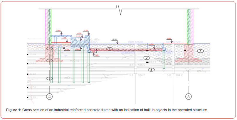
Civil engineers, geotechnical engineers, and design engineers always pay close attention to the construction of buildings and structures in cramped conditions [1-5]. Such construction is especially of genuine interest in the construction of objects within a functioning technological process, as the construction of a new building that complements it [6-13]. This article provides a wellimplemented geotechnical example of inserting an object. Fig.1 shows an explanatory cross-section of the industrial frame with an indication of the built-in objects in the operated industrial structure. The use of electric-discharge geotechnical technology in the construction of bored injection piles makes it possible to harmoniously arrange buried reinforced concrete structures in the above-mentioned conditions.
According to the results of the engineering and geological surveys, the construction site belongs to the III category of complexity of soil conditions. Geomorphologically, the survey area is confined to the northern part of the Volga Upland – the Chuvash Plateau and is located on the watershed surface between unnamed tributaries of the valleys of the Mal River. Civil and the Uta River. Engineering and geological structure of the construction site up to the depth investigated by drilling (18.0 m)) is represented by a thick stratum of Quaternary deposits of technogenic (tQh) and eluvial-deluvial genesis (edQh-p). From the hydrogeological point of view, the area up to the depth of 18.0 m investigated by drilling is characterized by the presence of one non-pressurized groundwater aquifer, penetrated in all wells from and confined to the quaternary bulk soils of IGE No. 1 and the roof of fractured eluvial-deluvial clays of IGE No. 2. The aquifer for the aquifer is served by the underlying denser layers of clay IGE No. 2 and 3.
The structural scheme of the built-in facility in the existing
operated building is as follows:
a) FM-1. Monolithic reinforced concrete structure consisting
of a floor, wall, columns, pile foundations, furnace foundations.
b) FM-2. Monolithic reinforced concrete foundation for
bunkers. The foundation is pile, on top of the bored injection
piles ERT are united by a monolithic reinforced concrete
grillage.
c) Monolithic reinforced concrete retaining walls PS-1, PS-2
- angle type on pile foundation.
Vertical “micropiles” of solid cross-section with a drilling diameter of 300.0 mm, reinforced to the full height with spatial reinforcement cages, were used as buried reinforced concrete structures. Accepted pile marking: SR-13-30 (length 13.0 m, drill diameter 300.0 mm); SR-15-30 (length 15.0 m, drill diameter 300.0 mm); SR-16-30 (length 16.0 m, drill diameter 300.0 mm); SR-17-30 (length 17.0 m, drill diameter 300.0 mm). Anchoring (reinforcement outlet from the pile head) into the monolithic reinforced concrete grillage (slab) is 400.0 mm, and the embedding of the pile head (reinforced concrete head) into the reinforced concrete grillage (slab) is 50.0 mm.
The sequence of installation of bored injection piles ERT is as follows in the following positions 1-18:
a. Self-compacting fine-grained concrete mixes of strength
class B25, waterproof grade not lower than W4 in accordance
with GOST 26633-2015 “Heavy and fine-grained concretes.
Specifications” prepared on the construction site or in
specialized concrete plants.
b. The concrete mixture must meet the requirements of
GOST 7473-2010 “Concrete mixtures. Technical conditions”.
c. Workability of concrete mixture P4... P5, tested by AZNII
cone.
d. Water separation of the concrete mixture is not more than
2%.
e. The concrete mixture should not have inclusions of
crushed stone and gravel with a size of more than 10.0 mm.
f. For concrete mixtures, use Portland cement without
mineral additives of a strength grade not lower than M500.
g. Quartz sand serves as an aggregate for concrete. It is
allowed to use clean fine sands with a fineness modulus of at
least 1.7.
h. The following additives may be used in the manufacture of
bored injection piles: superplasticizers, hardening accelerators,
setting retardants, corrosion inhibitors and antifreeze additives.
i. Tap and technical water for concrete mix, free of sugars
and phenols of more than 10.0 mg/l, petroleum products and
fats. The pH is between 4.0 and 12.5.
j. It is forbidden to add water to the fine-grained concrete
mixture to increase its mobility.
k. Selection of the composition of the concrete mixture with
determination of the composition and amount of additives is
carried out by the construction laboratory.
l. Reinforcement of piles is provided for the entire length
and is carried out in separate sections of spatial welded
reinforcement cages. Connect the frames to each other by
overlapping with the help of binding wire.
m. The longitudinal bars of the spatial reinforcement cage
are: reinforcement with a diameter of 18.0 mm of A500C
class; transverse reinforcement made of reinforcement with
a diameter of 10.0 mm of A240 class. The protective layer of
concrete is not less than 30.0 mm.
n. The stiffness of the spatial frame is provided by steel rings
made of pipes with a diameter of 159 mm and a wall thickness
of at least 4.0 mm.
o. In order to provide a protective layer of concrete,
centralizers made of steel strips with a width of 20.0 mm and a
thickness of 4.0 mm are provided in the amount of at least three
in one cross-section of the spatial reinforcement cage with a
spacing along the length of the frame of no more than 2.0 m.
p. Manual arc welding of the spatial frame elements is
carried out with electrodes of E42A, E46A, E50A types.
q. It is forbidden to use reinforcement made of 35GS steel
for the manufacture of welded spatial reinforcement cages.
Notes:
a) Anchoring (reinforcement outlet from the pile head) into
a reinforced concrete slab 400.0 mm.
b) Embedding the head (reinforced concrete head) of the
pile into a reinforced concrete slab of 50.0 mm.
c) Cover the surfaces of building structures buried in the
ground with bituminous mastic twice on a primed base.
r. Heavy concrete of strength classes B20, B25, water
resistance grade not lower than W4, frost resistance F100,
workability of concrete mixture P4-P5, checked by the
settlement of the AZNII cone.
s. The settlement of the cone of the concrete mixture is not
less than 21.0 cm, the size of the aggregate (granite crushed
stone) is not more than 40.0 mm.
t. Installation of foundations should be carried out on
preparation of B7.5 class concrete with a thickness of 100.0
mm.
u. Reinforcement of structures is carried out by separate
bars or frames. Longitudinal and transverse reinforcement
of class A500C. At the joints of the reinforcing bars, make
an overlap equal to 50 diameters of the reinforcement. The
protective layer of concrete for working reinforcement is not
less than 40.0 mm.
v. At all other intersections, connections should be made
with the help of binding wire.
w. Manual arc welding of rebar is carried out with electrodes
of E42A, E46A, E50A types.
The sequence of installation of monolithic reinforced concrete grillages on the heads of ERT bored injection piles is as follows:
a) When developing a pit for monolithic reinforced concrete
structures, in order to exclude the possibility of surface water
entering it on the basis of the requirements of pos. 1.3 SNiP
3.01.01-85 “Organization of Construction Production” As part
of the preparatory work, it is necessary to perform temporary
drainage from the construction site by planning the site area,
ensuring their rapid outflow using permanent or temporary
devices in accordance with the requirements of SNiP 3.02.01-
87 “Earthworks, Bases and Foundations”.
b) Before concreting structures, horizontal surfaces must be
cleaned of debris, dirt, oils, snow and ice, cement film, etc.
c) The concrete mixture should be laid in horizontal layers
without technological breaks with a direction in one direction.
d) If continuous concreting is not possible, it is allowed to
arrange working joints with their location in agreement with
the authors of the working project. Contact surfaces should be
cleaned of cement film. As a rule, the cement film should be
removed immediately after the cement has set (in hot weather
6-8 hours after the end of laying, in cool weather - 12-24 hours).
Cleaning of the concrete surface from the cement film should be
carried out without damaging the surface of the concrete, the
strength of the concrete should be within 2.0-3.0 kgf/cm2 when
treated with an air jet and 15.0-25.0 kgf/cm2 when machining
with a metal brush. It is forbidden to use percussion tools
(jackhammers, perforators, concrete breakers, etc.) to remove
the cement film from the concrete surface. Concrete mixture
prepared for laying the surface of the hardened working joints
should be coated with colloidal adhesive M400 (water-cement
ratio not more than 0.35) with a thickness of no more than 5.0
mm immediately before continuing concreting.
e) Compact the concrete mixture with vibrators until the
settling stops and the cement dough shines on the surface.
f) It is forbidden to use concrete mixture that has lost its
workability. Adding water to increase mobility is not allowed.
g) When compacting the concrete mixture, it is not allowed
to rest the vibrators on reinforcement and embedded products,
tie rods and other elements of formwork fastening. The depth
of immersion of the deep vibrator in the fine-grained concrete
mixture should ensure its deepening into the previously laid
layer by 5.0-1.0 cm. The step of repositioning of deep vibrators
should not exceed one and a half of their radius of action, for
surface vibrators it should provide an overlap of 100.0 mm
vibrator pad of the boundary of an already vibrated area.
h) In the initial period of hardening, concrete must be
protected from precipitation or moisture loss, and then
maintain a temperature and humidity regime with the creation
of conditions that ensure the growth of its strength.
i) Measures for the maintenance of concrete, the procedure
and terms of their hardening, control over their implementation
and the terms of dismantling of structures shall be established
by the PPR.
j) Movement of people on concreted building structures
and installation of formwork of overlying building structures is
allowed after concrete reaches a strength of at least 1.5 MPa.
k) It is not allowed to fill the sinuses of manufactured
structures with frozen soil (Figure 1).
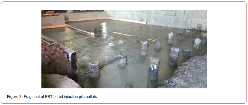
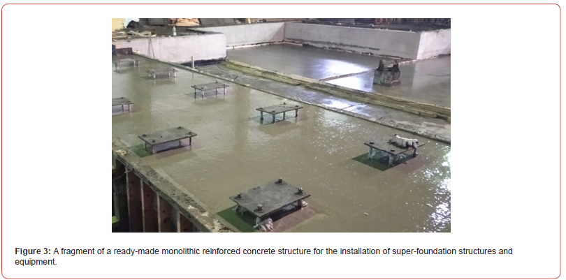
Figures 2 & 3 below show the actual outlets (heads) of the ERT bored injection piles, as well as a fragment of the monolithic reinforced concrete grillage along the heads of the ERT piles.


References
- Ilyichev VA, Mangushev RA, Nikiforova NS (2012) Experience in the development of underground space of Russian megapolises. Russian megacities underground space (2): 17-20.
- Ulitskiy VM, Shashkin AG, Shashkin KG (2010) Geotechnical support for urban development South Geotechnical support of urban development. Art Petersburg, Georeconstruction Publ, pp. 551
- Ilichev VA, Konovalov PA, Nikiforova NS, Bulgakov LA (2004) Deformations of the Retaining Structures Upon Deep Excavations in Moscow. Proc. Of Fifth Int. Conf on Case Histories in Geotechnical Engineering, New York, USA pp. 5–24.
- Ilichev VA, Nikiforova NS, Koreneva EB (2007) Computing the evaluation of deformations of the buildings located near deep foundation tranches. Proc. of the XVIth European conf. on soil mechanics and geotechnical engineering. Madrid, Spain, 24–27th September «Geo-technical Engineering in urban Environments 2: 581–585.
- Ilyichev VA, Nikiforova NS, Konnov AV (2021) Forecast of changes in the temperature state of the building foundation in the conditions of climate warming. Soil Mechanics and Foundation Engineering (6): 18–24.
- Nikiforova NS, Vnukov DA (2011) Geotechnical cut-off diaphragms for built-up area protection in urban underground development. The pros, of the 7thI nt. Symp. «Geotechnical aspects of underground construction in soft ground», 16–18 May, 2011. tc28 IS Roma, AGI, pp. 157.
- Nikiforova NS, Vnukov DA (2004) The use of cut off of different types as a protection measure for existing buildings at the nearby underground pipelines installation. Proc. of Int. Geotech. Conf. dedicated to the Year of Russia in Kazakhstan. Almaty, Kazakhstan, pp. 338–342.
- Petrukhin VP, Shuljatjev OA, Mozgacheva OA (2003) Effect of geotechnical work on settlement of surrounding buildings at underground construction. Proceedings of the 13th European Conference on Soil Mechanics and Geotechnical Engineering. Prague.
- Ter Martirosyan ZG, Ter-Martirosyan AZ, Angelo GO (2019) Interaction of crushed stone piles with the surrounding soil and grillage. Soil Mechanics and Foundation Engineering (3): 2–6.
- Pivar J (2011) Stone columns – determination of the soil improvement factor. Slovak journal of civil engineering 19(3): 17–21.
- Sokolov NS (2016) Technological methods of buroinjection pile construction with multi-place widening. 10: 54.
- Sokolov NS, Viktorova SS (2018) Method of Aligning the Lurches of Objects with Large-Sized Foundations and Increased Loads on them //Periodico Tche Quimica T. 15. Special Issue 1: 1-11.
- Sokolov NS, Petrov MV, Ivanov VA (2014) Problems of calculation of drilled piles, manufactured with the use of discharge-impulse technology. Proceedings of the VIII All-Russian (II International) Conference. Editorial Board: N.S. Sokolov (Editor-in-Chief), D.L. Kuzmin (Responsible Secretary), AN Plotnikov, LA Sakmarova, AG Lukin, VF Bogdanov, VI Tarasov pp. 415-420.
-
Sokolov Nikolay Sergeevich*. A Case from the Geotechnical Practice of Construction in Cramped Conditions. Cur Trends Civil & Struct Eng. 10(3): 2024. CTCSE.MS.ID.000739.
-
Geotechnical construction; electrohydraulics; monolithic reinforced concrete grillage; bored injection piles ERT; cramped geotechnical conditions; Iris Publishers, Iris Indexing Sites
-

This work is licensed under a Creative Commons Attribution-NonCommercial 4.0 International License.


