


 Review Article
Review of Mechanical Bar Couplers for Splicing Precast Concrete Members
Department of Civil and Environmental Engineering, Florida International University, Miami, FL 33174, USA
Received Date:December 19,2020; Published Date: January 12, 2021
Abstract
One of the methods for connecting precast concrete members is the application of grouted sleeve couplers. The use of this type of connection is becoming more common over the years and in many cases provides for a time-effective, labor-friendly, and economic alternative to other connection types. However, their application has been limited to non- or low-seismic regions due to the reduction in the ductility capacity attributed to these connections. Recent studies have shown that they can be implemented in the moderate and high seismic zones providing that they are placed in the locations away from damage protected members or arranged to allow yielding of connected bars. This paper aims at reviewing the performance of grouted sleeve couplers under tensile and bending loads as well as gathering in one place recent approaches in improving their ductility behavior. The results of this study are expected to pave the way for researchers to apply this type of connection in seismic areas and motivate new ideas for improving their performance.
Keywords: Mechanical Bar Coupler; Structural Splice; Precast Concrete Members; Prefabricated Elements; Grouted Sleeve Coupler; Ductility; Headed Sleeve Splice; Seismic Application.
Introduction
The application of precast members provides for a rapid, durable, and labor-friendly method of construction. Prefabricated elements are often joined by splicing or coupling steel reinforcement. Joining prefabricated elements can therefore be performed using mechanical splicer/couplers. Mechanical bar couplers have been in use since 1973 [1]. Among all types of mechanical bar couplers that include 1- Shear screw coupler, 2-Headed bar coupler, 3- Grouted sleeve couplers, 4- Threaded coupler, and 5- Swaged couplers, grouted sleeve couplers are most often used for connecting precast members. Also, the combination of threaded and grouted sleeve couplers have recently presented itself as an acceptable alternative.
Much research has been conducted to investigate the capacity, behavior, suitability, and effectiveness of grouted sleeve and threaded sleeve couplers that are used for concrete members. Their ability in carrying the tension loads have been proven effective through several pull-out experiments. Examples include:
1- Tests of grouted sleeve in the market (NMB) under monotonic loading by Jansson at Michigan DOT, 2008, and Einea et al., 1995 [2,3].
2- Static and dynamic tests of grouted sleeve and headed bars sleeve couplers at the University of Nevada, Reno, by Haber, 2013 and Tazarv, 2014 [4,5];
3- Tests of threaded sleeve couplers under monotonic and cyclic loadings by Kruavit et al. (2020) [6]
4- Dynamic and impact tests of grouted splices by Noureddine, (1995) and Rowell and Hager, 2010 [7]; and
5- Multiple tests of splice sleeves in Japan and Malaysia (NMB Splice Sleeve).
Due to the reduction in the ductility of member attributed to mechanical connections, however, the application of grouted sleeve splices/couplers in seismic regions has been limited or allowed with specific consideration/guidance as per ACI 318-14 and NCHRP report [8,9]. The reason for reducing the ductility is explained by higher rigidity of the coupler region compared to bars alone; thus, limiting the yielding at the connection zone. Recent investigations have devised means to improve this condition and raise ductility behavior in order to implement these connections in the seismic regions.
The goal of this paper is to review types of mechanical bar couplers and their performance under gravity as well as lateral loads. It will help researchers to know the tensile and ductile behavior of the grouted sleeve couplers as well as their failure modes. This paper also covers the design criteria for such couplers. As such, it paves the way for wider implementation of this type of connections for the precast concrete elements, especially in the seismic areas.
Mechanical Bar Couplers
Mechanical bar couplers offer an attractive time- and costeffective means for connecting precast elements. In general, they are divided into five categories (Figure 1). These are:

a) Shear screw couplers,
b) Headed bar couplers,
c) Grouted sleeve couplers,
d) Threaded couplers, and
e) Swaged couplers.
Shear screw splice is made of lock shear screw, shear rails, and coupling sleeve. Equal length of bars is placed into the sleeve from each side, then the screws are tightened till the heads of screw shear off. In headed bar couplers, the plated end of bars is encased in sleeves that are threaded into each other. In grouted sleeve, two bars are connected to each other by placing them into a steel sleeve followed by grout filling of the sleeve. In one version of grouted sleeve splice, the length required for coupler is reduced by adding threads inside the sleeve. In threaded couplers, the threaded bars are turned into a coupler with matching internal threads. Both straight and tapered threads have been used for the bar. In swaged coupler, straight bars are connected to pressed steel sleeve [10,11].
The most common type of mechanical couplers are grouted sleeve couplers. The load is transferred between the bars by the coupler. They have been used to connect prefabricated elements. One prefabricated element has the role of host. There are holes at the face of the host element to receive the protruding bars from the element to be connected. The connection between the host and the joining element is established when the bars are inserted into the sleeves and filled with the grout (Figure 2). Pouring the grout in the sleeve can be performed before positioning of the bars, referred to as pre-grout, or it can be performed after placing the bars in the sleeve using grout pump [9]. Figure 3 shows several types of couplers that are in the market.
Grouted Sleeve Couplers Under Axial Tensile Loads
The behavior of grouted couplers under monotonic axial load has been investigated by several researchers. Alias et al. [14] experimentally investigated the performance of grouted sleeve couplers under axial loads in which the connector employed a mild steel pipe filled with nonshrinkage grout. The role of the grout was to bond the reinforcing rebars with the connector. The sleeve connector received a bar at each end, and the bars met each other at the midlength of the connector and the grout was poured into the sleeve. Figure 4 shows the typical configuration of the connector.
They conducted pull out tests to investigate the performance of the connection under tensile loads. Eight specimens with different sleeve and development lengths were built and tested (Figure 5). All specimens were tested under incremental tensile loads until failure by using Universal Testing Machine. The average grout compressive strength at the time of the experiment was 6700 psi (46 N/mm2), and the tensile loads were applied to the splices/couplers with an average rate of 13.5 lbf/s (0.06 kN/s). Three modes of failure were identified in the pull-out tests; 1- fracture of the bar outside the connector (Figure 6a);
2- pull out of the bar from the grout (Figure 6b); and 3- pull out of the grout from the sleeve (internal sleeve-grout failure) (Figure 6c).


Based on the results, they concluded that the development length of the reinforcing bar is the most effective parameter in the performance of the connectors. Additionally, the required development length can be reduced to 10 times diameter, where, in the design standards, it is considered 40 times of bar diameter [14].
The development length reduction can be attributed to the confinement provided by the sleeve.
Einea et al. [2] investigated the bond strength of grouted sleeve couplers at failure. Yield strength of the bar, compressive and tensile strength of the grout, the properties of the sleeve, and the geometry of the bar as well as its confining condition were identified as variables that impacted the bond strength of reinforcing bars confined with sleeve. The bar diameter as well as its embedment length into the confined grout, the sleeve’s wall thickness, and the geometry of the sleeve’s ends were also of importance. They found a linear relationship between the bond strength at failure, U, and the square root of grout strength (Equation 1):
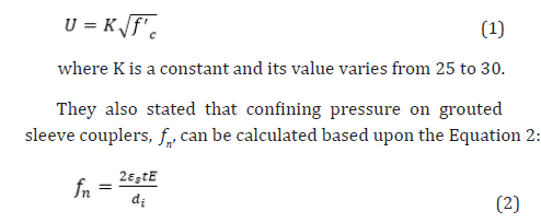
where ε s, t, E, and di are tangential strain in the sleeve, the thickness of sleeve wall, the module of elasticity of the sleeve material, and inside diameter of the sleeve, respectively [3]. From their work, it can be seen that as the inside diameter of the sleeve increases without changing its thickness wall, the confining pressure decreases. Hence, the ultimate bond strength decreases. With decreasing the bond, the capacity of the splice decreases. Also, as the wall thickness of the sleeve, t, increases, the confining pressure increases. Thus, the ultimate bond stress increases. Accordingly, the splice capacity increases.
Seo et al. (2016) investigated a type of mechanical grouted coupler called headed-splice sleeve (HSS) (Figure 7). This splice has a large opening on one end and a small opening on the other. Through the large opening, the rebar with head connected mechanically to the rebar is inserted into the sleeve. The smaller opening is threaded and receives the other rebar by threading into the sleeve. The grout is poured into the sleeve to bond and anchor the headed rebar and to provide the splice with its capacity. In their investigation, the bond behavior of the splice system was studied. Variables of their studies were development length of the rebar and presence and size of the head. They found that the presence of the head prevented the brittle failure of splice. In other words, it caused the failure to occur with the failure of the rebar rather than the grout failure. Also, they noticed that the diameter of the head was dependent on the geometry of the sleeve and calculated the proper ratio of diameter of the sleeve to diameter of the head to be 1.3 [15].
In their work, the bond strength of the HSS was calculated by Equation 3.

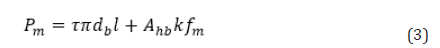
where Pm is the maximum bond strength (N or lb); k is 3.4 based on the analysis results; l is the development length of the rebar (mm or in.); and τ is the bond stress obtained in the experimental test (N/mm2 or psi) and calculated by Equation 4. Ahb is the improved bearing area by head anchorage device (mm2 or in2), calculated by Equation 5.

where db is the diameter of the rebar (mm or in.), and fm is the compressive strength of grout mortar (N/mm2 or psi).

where Am is the mortar bearing surface area (area inside the sleeve) (mm2 or in2) and Ah is the bearing area of head (mm2 or in2 ) [15].
Another type of grouted sleeve coupler in precast members (Figure 8) was investigated by Henin and Moracous (2014). This coupler was deemed to be more cost-efficient and easier to implement than the proprietary couplers including, NMB Splice Sleeve, Sleeve Lock by Dayton Superior, and Lenton Interlok [16].

Their proposed sleeve coupler is a grout-filled round pipe in which the diameter, length, and thickness of the sleeve are determined based on the bars to be spliced. Design of the sleeve is based upon shear-friction theory for transferring the force of one bar to the grout, from the grout to the steel pipe, from the steel pipe to the grout, and at the end from the grout to the other bar.
In their investigation, two types of grouted sleeve coupler, Types P and T, as shown in Figure 9, were designed and tested. Type T had threads along the interior surface of the entire sleeve, while Type P had the threads at the upper part only and was welded to a steel plate at the bottom part.

Their study included testing of 18 specimens, 9 specimens of each type with different sleeve length. According to the test results, the embedment length of the bar (𝑙b) was calculated (Equation 6), in which 𝑑b is the diameter of the bar, P is the force, and Fb is the bond strength between the bar and the surrounding grout.
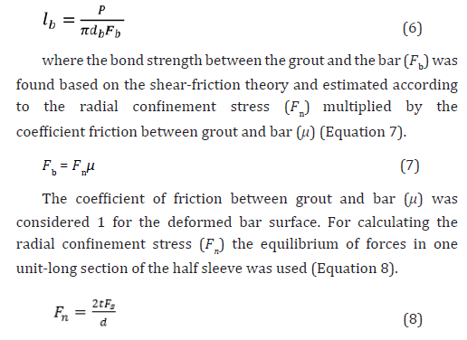
where t, 𝐹s, and d are the wall thickness, yield stress, and inside diameter of the sleeve, respectively. They also found that to avoid crushing failure of grout, the radial confinement stress should be less than 0.2f’c, where f'c is the compressive strength of the grout. Finally, for the proposed sleeve coupler, the required embedment length of the splices was calculated based on Equation 9.
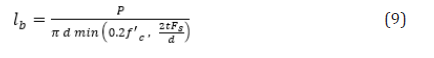
The required sleeve length (𝑙s) was also estimated to be twice the embedment length rounded up to the nearest inch [16].
Grouted Sleeve Couplers for Elements Subject to Lateral Loads
Although strength has been the most important criteria for the application of grouted sleeve couplers for many years, reaching sufficient ductility has recently emerged as a concern [17]. Significant amount of research has been conducted to investigate the effect of grouted sleeve couplers on the ductility of the precast members in seismic regions. It was found, in many cases, that the connection made with grouted couplers is too rigid to allow yielding within its length. Thus, the entire elongation occurs in the rebar close to the end of the sleeve. Therefore, the ductility of the member is reduced. Many approaches, including debonding the bars and moving the grouted sleeve couplers farther inside the elements, have been implemented to improve the ductility performance of these connectors in the precast elements.
Haber e t a l . [4] and Pantelides et al. [18] investigated the displacement ductility of several precast column connections using grouted and headed sleeve couplers. The results are summarized in Table 1.

As shown in Table 1, for precast column connections using grout filled coupler (GC), displacement ductility ratio is as low as 60 % of that of cast-in-place (CIP) connections.
In their research, Tazarv and Saiidi, 2014, 2015, and 2016, developed an approach to quantify the reduction in the displacement ductility. Based on the pull-out tests and numerical simulations, they found that reduced analytical plastic hinge length, Lspp, due to the presence of any type of mechanical coupler can be calculated based on Equation 10 [5,10,19].

where:
Lspp: Reduced analytical plastic hinge length due to the presence of the mechanical coupler (in.)
L𝘱: Analytical plastic hinge length for CIP members as defined in AASHTO Guide Specification for LRFD Seismic Bridge Design (2011) (in.)
HSP: Distance from the top surface of member to the nearest end of the mechanical coupler (in.)
Figure 10 shows the actual and idealized curvature diagram for the column with grouted sleeve coupler in the plastic hinge region.

Several solution schemes have been attempted to improve the ductility behavior of the grouted sleeve couplers in precast members. Debonding of connected bars outside the coupler (Figure 11) was found to be an effective approach since it postpones the rebar fracture and reduces spalling of adjacent capacity-protected elements [20-22]. Accordingly, the ductility of the system and as a result, the energy dissipation capacity of the structure will be increased with debonding solution. Pantelides et al., 2014, experimentally studied the effect of debonding of bars on the ductility of the member. They found that debonding increased the displacement ductility capacity from 5.4 to 6.8. There is a need for more research to investigate the effect of debonding material, debonding length, and location of debonding on the ductility behavior of a member in seismic regions [18].

Tazarv and Saeidi (2014) investigated another approach to improve the ductility of the system. They shifted away the location of the grouted sleeve couplers from the column ends to emulate the seismic response of CIP counterparts in terms of energy dissipation and displacement capacity (Figure 12). They found that this approach combined with debonding can effectively increase the ductility of the system.

Grouted Sleeve Couplers in The Design Specifications
ACI 318-14 defines two types of mechanical bar couplers, Type 1 and Type 2. Type 1 is referred to as the connectors that can develop 125% of the yield strength of the bars A( b 𝐹y ). Type 2 is referred to as the couplers that can both conform to the requirement of Type 1 and can develop the ultimate strength (nominal tensile strength 𝐹u) of the bars to be joined. ACI 318-14 requires using the Type 1 only in the locations in which the couplers shall not experience yielding. This requirement ensures that premature failure, bar pullout or coupler fracture will not impact the system’s ductility. Therefore, Type 1 of mechanical couplers is not allowed to be implemented in plastic hinge regions for all Seismic design categories (SDCs). However, Type 2 is permitted to be used anywhere except within half a member depth from the face of the connecting element in special moment frames (SMF) with ductile connections if the connections are not “strong” [8].
AASHTO LRFD does not use Type 1 and 2 terminologies. It requires that in SDCs C and D (Seismic Zone 3 and 4), any mechanical coupler to be used outside the plastic hinge region [23]. It also determines that in piles or shafts, where such placement is virtually impossible, mechanical couplers can be used in plastic regions if they develop the tensile strength of the bars.
Summary and Conclusion
In this study, the performance of a grouted sleeve couplers under the tensile and lateral load was investigated. The limitations on their application were discussed and recent approaches to overcome this constraint was reviewed and explained. Following is a summary of the results:
1. Mechanical bar couplers are divided into 5 categories: (a) shear screw couplers, (b) headed bar couplers, (c) grouted sleeve couplers, (d) threaded couplers, and (e) swaged couplers. Among all, grouted sleeve couplers are used most for splicing precast members.
2. The most effective parameter for the performance of grouted sleeve couplers under tension load is the development length. The required development length was reported to be at least 10 times the bar diameter.
3. The capacity of grouted couplers is related to their bond strength. As the inside sleeve diameter increases the confining pressure decreases; hence, the bond strength decreases. Accordingly, the splice capacity decreases.
4. The presence of head in the headed-splice sleeve prevents premature failure of the splice as it results in the bar rupture rather than grout failure. Therefore, it helps to avoid brittle failure.
5. In headed sleeve splices, the head diameter is reliant on the sleeve geometry, and the ratio of the diameter of the sleeve to the diameter of the head can be estimated to be 1.3.
6. Two methods are used to increase the ductility performance of the grouted sleeve couplers under lateral loads: 1- Shifting away the location of the grout-filled coupler from the end of connection (and away from damage protected members) and 2- Debonding of bars outside the grouted sleeve coupler.
7. The debonding approach can increase the ductility capacity of the member up to 25 percent.
In a parallel research study, the authors have provided a general review of means and methods for splicing precast piles complementing the study reported in this paper [24].
Acknowledgments
The study reported in this paper is supported by the Accelerated Bridge Construction University Transportation Center (ABC-UTC, www.abc-utc.fiu.edu) at Florida International University (FIU) under a grant from the U.S. Department of Transportation Office of Research, Developement and Technology, University Transportation Centers Program, Grant No. 69A3551747121. The contents of this report reflect the views of the authors, who are responsible for the facts and the accuracy of the information presented herein.
Declaration of Competing Interest
The authors declare that they have no known competing financial interests or personal relationships that could have appeared to influence the work reported in this paper.
References
- Yee A (1973) New precast prestressed system saves money in Hawaii PCI J 18: 10-3.
- Jansson PO (2008) Evaluation of grout-filled mechanical splices for precast concrete
- Einea A, Yamane T, Tadros MK (1995) Grout-filled pipe splices for precast concrete construction. Pci J40: 82-93.
- Haber ZB (2013) Precast column-footing connections for accelerated bridge construction in seismic zones. University of Nevada, Reno,
- Tazarv M (2014) Next generation of bridge columns for accelerated bridge construction in high seismic zones. University of Nevada, Reno,
- Kruavit P, Ruangrassamee A, Hussain Q (2020) Experimental and Analytical Study on Reinforcing Steels with Threaded Mechanical Couplers under Monotonic and Cyclic Loadings. Eng J24: 61-70.
- Rowell SP, Hager KP (2010) Investigation of the dynamic performance of large reinforcement bar mechanical Struct. Congr pp. 2059- 2075.
- ACI Committee (2014) 318, Building Code Requirements for Structural Concrete (ACI 318-14) and Commentary (ACI 318R-14). Am Concr Institute, Farmingt Hills, MI, pp. 519.
- Culmo MP, Marsh L, Stanton J, Mertz D (2017) Recommended AASHTO Guide Specifications for ABC Design and
- Tazarv M, Saiidi MS (2016) Seismic design of bridge columns incorporating mechanical bar splices in plastic hinge Eng Struct 124: 507-520.
- Mehrabi AB, Khedmatgozar Dolati SS (2020) Alternative Materials and Configurations for Prestressed-precast Concrete Pile Splice
- Redd SC (2016) Strength, durability, and application of grouted couplers for integral abutments in accelerated bridge construction projects.
- (2020) Mechanical couplers in market (Nvent).
- Alias A, Sapawi F, Kusbiantoro A, Zubir MA, Abd Rahman AB (2014) Performance of grouted splice sleeve connector under tensile load. J Mech Eng Sci 7: 1096-1102.
- Seo S-Y, Nam B-R, Kim S-K (2016) Tensile strength of the grout-filled head-splice-sleeve. Constr Build Mater 124: 155-
- Henin E, Morcous G (2015) Non-proprietary bar splice sleeve for precast concrete Eng Struct 83: 154-162.
- Marsh ML (2011) Application of accelerated bridge construction connections in moderate-to-high seismic regions. vol. 698. Transportation Research Board.
- Pantelides CP, Ameli MJ, Parks JE, Brown DN (2014) Seismic evaluation of grouted splice sleeve connections for precast RC bridge piers in ABC. Utah Department of Transportation.
- Tazarv M, Saiidi MS (2015) Design and Construction of Bridge Columns Incorporating Mechanical Bar Splices In Plastic Hinge Zones.
- Belleri A, Riva P (2012) Seismic performance and retrofit of precast concrete grouted sleeve
- Cohagen LS, Pang JBK, Stanton JF, Eberhard MO (2008) A precast concrete bridge bent designed to re-center after an earthquake. TransNow Seattle, WA, 684.
- Mashal M, White S, Palermo A (2014) Experimental testing of emulative connections for accelerated bridge construction in seismic areas. Austroads Bridg. Conf. 9th Sydney, New South Wales, Australia.
- AASHTO (2017) AASHTO LRFD Bridge Design Specifications (8th edn) American Association of State Highway and Transportation Officials, Washington, D.C, USA.
- Dolati SSK, Mehrabi A. Review of available systems and materials for splicing prestressed-precast concrete Structures 2021; 30:850–65. https://doi.org/10.1016/j.istruc.2021.01.029.
-

This work is licensed under a Creative Commons Attribution-NonCommercial 4.0 International License.


