


 Research Article
Modelling and Controlling a Dexterous Walking Space Manipulator for In-Orbit Missions
Received Date:January 22, 2024; Published Date:February 15, 2024
Abstract
Robotics, Automation and Autonomous Systems are the main pillars for large-scale futuristic in-orbit missions. The state-of-the-art semiautonomous robotic manipulators in orbit are operated from the International Space Station and have limited walking features restricting their workspace. Hence, they cannot efficiently assemble complex infrastructures in-situ, such as space telescopes and space-based solar power. To overcome the technological gaps in the conventional space manipulators, the next generation of walking space manipulator, known as the End-Over- End Walking Robot (E-Walker), is introduced. The E-Walker’s inbuilt redundancy and modular design offers enhanced workspace utilization, greater agility and maneuverability both for in-space missions and other terres- trial applications. The assembly mission Concept of Operations (ConOps) dealt in this paper is the modular Large Aperture Space Telescope (LAST) and presents the modelling of a fully dexterous seven degrees-of-freedom E-Walker with its gait analysis and control. The closed-loop performance of the E-Walker is analyzed under perturbed microgravity conditions using two widely used space-proven controllers
a. The Proportional-Integral-Derivative controller coupled with the Computed-Torque-Controller (PID-CTC) and
b. The robust H∞ controller. The simulation results prove E-Walker’s efficacy for accomplishing multiplex in-situ assembly of a large aperture space telescope.
Keywords:In-Space Services; End-Over-End Walking Robot; Modelling; Robust Control
Introduction
In-orbit missions are being scaled up to meet the growing scientific demands of the space community. The candidate inorbit missions include servicing, assembly, manufacturing, repairs, recycling, and Active Debris Removal (ADR) [1-12]. Amongst in-orbit assembly missions, the assembly of Space-based Solar Power (SBSP) generation, Active Debris Removal (ADR), and large aperture space telescopes for astronomy and earth observation are gaining momentum [13-18]. The drive to establish advanced robotic systems for these missions is attributable to the escalating concern over human safety in the extremities of the space environment. Astronauts conducting Extra- Vehicular Activities (EVA) on the International Space Station (ISS) are prone to numerous risks including suit leaks, accidental detachment from the spaceship, exhaustion, sickness etc. [19]. Additionally, the development of advanced space suits with added protective measures to support EVA significantly increases the mission cost [20]. Integrating autonomous robotic systems to support large-scale in-orbit missions has numerous added benefits which include flexibility, precise manoeuvring, repeatability, task sharing, time management etc., when compared to EVA. However, the Guidance, Navigation and Control (GNC) is highly challenging for these missions given the complexities involved due to the parametric uncertainties and external disturbances in the space environment [21]. The precise manoeuvring of the space robot relies heavily on the attitude stabilization of the base spacecraft and the trajectory control of the robotic manipulator as a whole.
Space robots are widely classified into,
Free-Flying Space Robots - base remains fixed and is controlled, restricting the workspace of the spacecraft.
Free-Floating Space Robots - base is in motion as it is uncontrolled [22, 23]. In [24-27], the authors presented another classification.
Controlled-Floating Space Robot (CFSR), where the base is free to move but in a controlled manner providing an unlimited workspace.
The free-flying concept would be majorly used in future In-orbit Servicing, Assembly and Manufacturing (ISAM) missions where the scale of the mission is large, and a base station is constructed for the mission. In the free-flying space robot, the attitude of the base spacecraft is stabilized, and the candidate robotic architecture utilizes the platform to perform the tasks assigned. A CFSR concept on the other hand could be used for any missions involving ISAM, ADR and inclination correction. During an ADR mission, the chaser space robot tries to capture a cooperative or non-cooperative target. The CFSR would try to match the motion of the target prior to capture and restrict the cumulative motion post capture. The GNC problem for a Free-Flying Space Robot and the CFSR is to maintain its attitude due to the non-linear dynamic coupling effects between the spacecraft platform and the fixed-to-base robotic manipulator. Understandably, the GNC problem is much more complex when the CFSR is in motion compared to a Free-Flying Space Robot with a stationary base spacecraft [24,27]. The CFSR concept can be extended to dual or multi-arms.
This paper mainly focuses on the Large Aperture Space Telescope (LAST) mission which involves a space robot. The potential robotic architectures for such missions include,
Railed manipulator These are robotic manipulators mounted on a mobile base. Even though robots on a rail offer an enhanced workspace, it is often confined to the fixed operating environment, which imposes various constraints. Additionally, the cost and mass of the mission increases significantly as it requires additional structures to be built around the spacecraft; the tracks limit the robotic manipulator to access the whole mission workspace [28].
Walking manipulators: These are robotic manipulators with capabilities to walk around the spacecraft platform via connector ports. They provide an enhanced workspace when compared to conventional fixed-to-base or railed robots.
The current state-of-the-art semi-autonomous robotic manipulators in orbit are operated from the ISS - the Canadarm2 and the European Robotic Arm (ERA) respectively [29-32]. However, these robots have limited walking features limiting their workspace. Overall, the basic need for the next-generation space robotic manipulators is to benefit from an innovative design with inbuilt redundancy that offers significantly enhanced workspace, greater agility, dexterity, and maneuverability. The design should be optimized to minimize the mass, volume, launch cost, and power requirements for the whole mission. To meet these requirements, a fully dexterous robotic manipulator with in-built mobility is an essential payload for numerous upcoming in- orbit missions. Such walking manipulators could also undertake the construction of human habitats on the Moon and Mars.
In this paper, the robotic system designed to carry out futuristic in-orbit tasks is a seven Degrees-of-Freedom (DoF) End-Over-End Walking Robot (E-Walker) [17]. Both ends of the E-Walker are equipped with an end-effector to latch onto the static connector ports made available on the spacecraft platform. The redundant design along with its improved elbow joint design helps the E-Walker with added mobility features compared to the Canadarm2 and the ERA. The offset in the Canadarm2’s elbow joint provides it with the end-over-end walking capability. However, it requires an additional rail of connectors to be placed at a distance of the offset to facilitate this motion. The ERA’s elbow joint is limited to 180 degrees, which limits its walking to an end-to-end motion. The Modular spacecraft assembly and reconfiguration demon- strator (MOSAR) project involves an autonomous walking robotic manipulator to assemble modular spacecraft components [33,34]. The project was a feasibility study in which the walking robot performed assembly tasks of modular spacecraft components in earth-analogue conditions. In [35] the specifications for the earth-analogue and proposed space-based design of the candidate walking manipulator are presented. The motion of the MOSAR robot is a replica of the ERA, limiting itself to an end-to- end motion. During an end-to-end motion, the walking manipulator relies heavily on its roll joints in either shoulder, which is undesirable for a space mission. A failure of one of these joints would limit its end-to-end motion. On the other hand, the E-Walker design takes into account all the advantages of Canadarm2, ERA and MOSAR and provides a robotic solution with added mobility features as depicted in Figure 1.

Previous studies include the design engineering and feasibility of the E-Walker to assemble a 25m Large Aperture Space Telescope (LAST) [17], gait pattern analysis, modelling and control, of a five DoF E-Walker to assemble a 25m LAST [36-39]. To address the constant clamour for redundancy and dexterity within robotic manipulators for space-missions, this paper presents a seven DoF E-Walker. In addition to covering the high-level design of the seven DoF E-Walker, the kinematic and dynamic modelling, joint limits and accessible workspace are presented. E-Walker’s gait pat- tern is analyzed to elaborate on the different phases involved during its motion in a straight-line path.
The non-linear dynamic model of the E-Walker is then simulated in a closed loop using a Proportional-Integral-Derivative controller coupled with the Computed-Torque controller (PID-CTC). Additionally, the robustness of the system is further evaluated using an H-infinity (H∞) controller. These two control methodologies were chosen due to their wider use. The PID controller is utilized by 90% of industrial systems for process and motion control and more than 99% of space missions have used PID controllers since 1957 [40,41]. On the other hand, amongst the wide range of nonlinear controllers currently available, the H∞ controller is being widely used for space applications now a- days [42-45]. Given the popularity of both these controllers, their performances are analyzed under perturbed conditions using simulation results carried out over a cycle of E-Walker’s motion. The desired joint parameters of the E-Walker are tracked to meet the required configuration.
The rest of the paper is organized into four sections. Section 2 discusses the kinematic and dynamic model of the seven DoF E-Walker along with its gait pattern analysis. In Section 3, the E-Walker’s robust closed-loop control equations with a PID- CTC and H∞ controller is presented. Section 4 analyses the performances of each of these controllers in a MATLAB/Simulink platform. Section 5 provides the conclusions of this paper and an insight into future research.
End Over End Walking Robot
The E-Walker is a walking robotic manipulator with the capability to be mobile around its base platform. The proposed design of the E-Walker has seven Degrees-of-Freedom (DoF), comprising of three revolute joints, each in the shoulder and the wrist. The symmetricity of the manipulator is maintained across its one DoF in the elbow joint. In addition to inbuilt redundancy, the E-Walker robot benefits from a modular design that offers significantly enhanced workspace, greater agility, and manoeuvrability. Unlike any other fixed-to-base robotic manipulator, the E-Walker has the capability to be mobile around its base platform in any direction. The movement can be considered as a replica of the “Queen” in the game of chess, in a 3D space. In addition to the seven joints, two grasping mechanisms on either end help form a rigid contact to the base. For terrestrial applications, the grasper could be magnetic, adhesive, fingered etc., based on the task-in-hand. For a space-based application, the grasper is a Latching-End-Effector (LEE), forming a rigid connection between the E-Walker and the spacecraft platform. The LEE provides the necessary mechanical, data and power connection for the E-Walker. The LEE latches onto the grapple fixtures on the connector ports available on the spacecraft. The added mobility features of the E-Walker compared to the conventional walking robotic manipulators identifies it as a potential candidate for future space and terrestrial activities. [17] presents the feasibility of a dual E-Walker system for assembling a 25m LAST in orbit (Figure. 2).

Seven DoF E-Walker Kinematics

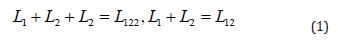
The kinematics of the seven DoF E-Walker comprises the forward and inverse kinematics. The forward kinematic analysis considers a three-dimensional (3D) coordinate system at the Centre of each joint. The inertial reference frame with origin o is shown in Figure 3a. The axis of rotation for each joint can also be visualized in this figure. The joints are defined by qi, where i represents the ith joint, i =1− 7 . The distance between each joint is considered to be LiThe two principle links are considered to be of length L3, the distance q 1-2 and q 2-3 is considered to be L2. The distance from the end effector tip to q1 is considered to be L1. Additionally,
The forward kinematic analysis was performed utilizing the Denavit Hartenberg (DH) convention to select frames for reference and interpret the end-effector position and orientation based on the joint parameters [46]. Figure 3
Joint limits and Workspace
Based on the joint constraints due to actuator sizing and
positioning in the E-Walker design, joints q1 and q1 connected to
the grippers, would have the ability to rotate 360 degrees around
the Z-axis. Joints q3,4,5 would rotate around the X-axis, whereas q 2,6 would rotate around the Y-axis of the inertial reference frame,
shown in Figure 3. During a space mission, the E-Walker would
latch on to connector ports available to manoeuvre around the
spacecraft platform, much like the Canadarm2 and the ERA on the ISS. With one end of the E-Walker fixed to the static connector ports
at all times, the other end can be treated as a wrist with a gripper to
perform manipulation tasks. For a one-step pick and place operation
within the reach of the E-Walker, six DoF would be adequate to
reach a point in 3D space. Therefore, one joint of the fixed end is
fixed at its initial position (θ 2 = 0 in Phase-1 and θ6 = 0 in Phase-2).
Joints q2 and q6 can be utilized for multi-step operations, which
includes transferring the E-Walker from one connector port to
another in their respective phases of motion. Additionally, due to
the symmetric design of the E-Walker, the lower limit of the elbow
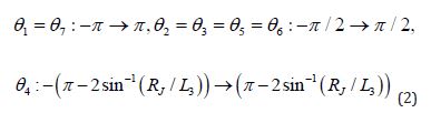
joint q4 as shown in Figure 4, is 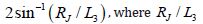 denotes the radius of the joint. The limitations of all the joints can
therefore be enlisted as follows:
denotes the radius of the joint. The limitations of all the joints can
therefore be enlisted as follows:
Referring back to Figure 3, the maximum reachability for q3 would be 

Inverse Kinematics
The next step is to derive the inverse kinematics of the seven
DoF E-Walker using Figure 5. The end-effector CoM attached to q7 is denoted as d. The top view of the E- Walker on the X-Y plane,
in the inertial reference frame, can be seen in Figure 5a. Joints q5-7 are responsible for the orientation of the gripper. In case of
grasping a PMU or fractional PMS from the Ssc, the robot gripper
should be held perpendicular to the connector port around the
mirror segments. This is also a crucial step in the case of normal
walking motion. Figure 5b shows E-Walker’s wrist joints in a 3D
plane, with an object placed arbitrarily. Lengths d1, d2 and d3 are
the positions of the object relative to q6 in the reference coordinate
system. Now, considering the object’s orientations as the desired
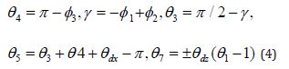
directions of the gripper, the joint angles θ1 and θ6 for Phase-1 can
be calculated from Figure 5a and 5b as:
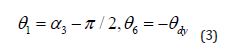
Considering Figure 5c, the angles of joints q 3,4,5,7 are derived as follows:
In Phase 2, the end-effector attached to q7 is fixed to the base. The inverse kinematic modelling will see a switch in the kinematic formulation. Joint q7 ’s formulation in Phase-1 will be taken up by q1 in Phase-2, wherea q2,3 q2,3 ’s formulation in Phase-1 will be taken up by q5,6 in Phase-2 respectively.
Seven DoF E-Walker Gait Pattern
The E-Walker’s motion is comprised of two phases of motion. Figure 3 shows E-Walker’s motion across a straight-line trajectory on a spacecraft platform. The E-Walker starts at an initial position as shown in Fig. 3a. During Phase-1, LEE1 is fixed to the base and LEE2’s motion is tracked (Figure 3b). Figure 3c shows Phase-2, where LEE2 is locked and LEE1’s motion is tracked, completing the first cycle of motion. The cyclic motion helps the E-Walker to move forwards or backwards in any direction. During any phase of its motion, one end of the E-Walker is always fixed-to-the-base, minimizing the Guidance, Navigation and Control Requirements when compared to conventional space robot concepts. The modular design benefits the E-Walker to be sized based on the mission workspace. This breaks the usual norm of building a large robot for a large mission.
Seven DoF E-Walker Dynamics
Using the Euler-Lagrange equation [46], the non-linear dynamic equation of the E- Walker is given as:
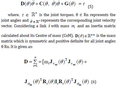

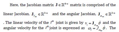
mass matrix is a crucial component in the robot dynamic equation and plays a significant role in robot control.
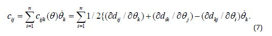
D(θ)  is also useful to calculate , which comprises
the Coriolis and Centrifugal forces. These forces act contrary to the
motor commands and can be given by:
is also useful to calculate , which comprises
the Coriolis and Centrifugal forces. These forces act contrary to the
motor commands and can be given by:
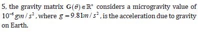
During a space mission, due to the micro-gravity conditions, the effect of potential energy is usually neglected. However, near-less gravity plays an important role in the control of robot dynamics in orbit and is taken into consideration in this paper. In Equation
E-Walker Control
The desired behavior of the dynamical systems used in today’s large-scale industries is maintained using closed-loop controllers. From the field of process control to aerospace engineering, controllers facilitate the efficient working of all the equipment onboard. Two well-established controllers in the space community are integrated into the non- linear dynamic model of the E-Walker under perturbed conditions. The E-Walker’s joint parameters are tracked to attain the desired performance.
PID-CTC for E-Walker Dynamical Model
For the initial verification of the E-Walker model, the widely used Proportional- Integral-Derivative (PID) controller is used. The PID control law in terms of the error dynamics is given as follows:

Although PID controllers are used in the majority of industrial applications, conventional PID controllers are not robust enough for various applications such as time-varying processes, large time delays, inherent non-linearities and disturbance rejections [47]. As future large-scale space missions would be prone to varied external and internal disturbances generated within the system, the conventional PID controller will not provide adequate robustness for the E-Walker’s accurate position and motion control.
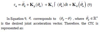
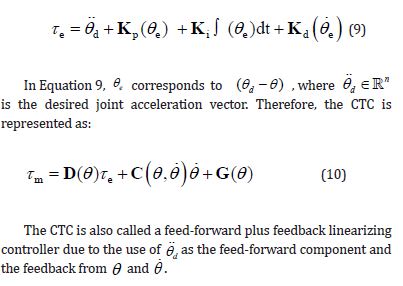
The E-Walker can overcome this shortcoming by using a Computed Torque Controller (CTC) alongside the PID controller. A CTC would convert the nonlinear dynamical system into a linear one using feedforward compensation. The desired joint parameters are defined based on a trajectory function. The error signal is calculated between the desired and actual system response, which helps the system achieve the required performance.
The CTC control equation is given as:
Nonlinear H∞ Controller for E-Walker Dynamical Model
Controlling the non-linear system dynamics under perturbed conditions is difficult for classical linear controllers such as the PID controller. Further, the linearized model used by the PID-CTC does not accurately represent the nonlinear characteristics of the E-Walker. Therefore, there is a necessity to design nonlinear controllers to guarantee the stability and robustness of the closedloop system. The H∞ controller when applied to a non-linear mathematical model, guarantees a pre-defined attenuation of the disturbances affecting the system [48,49].
Now, Equation 5 can be re-written to express it in the terms of nominal and uncertain parameters, whilst considering the external disturbance:
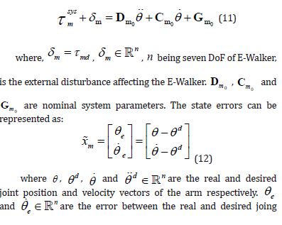
positions and velocity vectors respectively. The Nonlinear H∞ controller depends on few tuning parameters for optimal tracking of the desired trajectory. The parameters have to satisfy the condition set by the following Ricatti equation [49]:
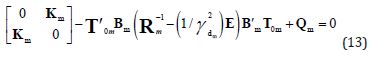
The equations for the parameters introduced in Equation 13 are presented below. The control algorithm requires parameters Qm its sub-matrices along with the attenuation ydmis to be defined by the user. The term Qm is defined as:
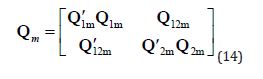
where 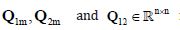 represents the weighing
matrices which is to be defined by the control designer. Km is a
positive definite matrix and is defined by the elements of the Qm matrix:
represents the weighing
matrices which is to be defined by the control designer. Km is a
positive definite matrix and is defined by the elements of the Qm matrix:

Now, given an attenuation level  the Rm matrix is
automatically selected from a range of bounded random values to satisfy equations as
the Rm matrix is
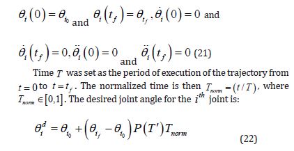
automatically selected from a range of bounded random values to satisfy equations as 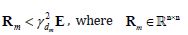 comprises of
the tuning parameters of the controller and
comprises of
the tuning parameters of the controller and  is an identity
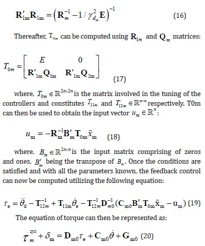
matrix. Once the values for these parameters are obtained, R1m can
be solved using the Cholesky factorization as follows [49]:
is an identity
matrix. Once the values for these parameters are obtained, R1m can
be solved using the Cholesky factorization as follows [49]:
E-Walker Trajectory
The trajectory of the E-Walker is defined by a 5th order polynomial function P(T′) that satisfies all initial and final conditions for the joint parameters [27]. It helps to avoid any discontinuities in acceleration and impulsive jerks, thereby improves the tracking accuracy [50]. The initial and final conditions of the joint parameters are as follows:
Table 1: External Disturbances used in Simulations.

The high-level simulation model of an E-Walker onboard a spacecraft is shown in Figure 6
Simulation Results of E-Walker
For the simulations, the links and joints of the E-Walker are considered to be hollow cylindrical. The distance 122 L from Figure 3 is considered to be 0.5m, and the distance 3 L is considered to be 3.5m. Based on these link lengths and joint offsets, the dynamic model of the E-Walker was simulated in MATLAB/Simulink. This section presents the performance of the E-Walker’s joint parameters over one cycle of its motion, controlled using a PIDCTC and non-linear H∞ controller. Throughout these simulations, microgravity conditions are considered with acceleration due to gravity (g = 9.81ms2) having a value of 10−6 g . Disturbances are introduced into the simulations to test the robustness of the PIDCTC and H∞ controller. External disturbances on the E-Walker can come in various forms, like gravity gradient, aerodynamic drag, solar radiation and magnetic torque [51, 52]. This explains why the space environment is extremely dynamic and dependent on a multitude of parameters. Additionally, random vibrations are also experienced in space affecting the dynamics of the E-Walker. These forces are generally of the magnitude 10-17→10-3NM [51]. Based on the given data, the simulation also considers external disturbances with values much higher than what is typically encountered. Sinusoidal noise and Gaussian random noise of zero mean are introduced into the non-linear dynamic model of the E-Walker. Table 1 presents the data of the external disturbances used, whereas Figure 7 shows the graphic. The random gaussian and sinusoidal waves are shown in Figure 7a and 7b respectively. Figure 7c presents the net external disturbance on the E-Walker.
In a straight-line trajectory, joints q3−5 play an important role as they help the whole system perform an end-over-end motion. For the simulations, the joint con- figurations used were A = [90; 90; 0; 0; 0; 90; 90], B = [90; 90; 30; 120; 30; 90; 90] and C = [90; 90; −30; −120; −30; 90; 90]. Understandably, from the joint configurations, three joints(q3-5)are sufficient to move the E-Walker along a straight line. One cycle is comprised of two phases. In Phase-1, the E-Walker moves from configuration A-B.


The simulation is run from t = 0s: 30s. During Phase-2, the E-Walker moves from configuration C-B, and the simulation is run from t = 30s: 90s, s being in seconds. For Cycle-1, Phase-1’s motion is half the motion as in Phase-2. For multiple cycles, Phase-1 would also begin from configuration C and go to configuration B, requiring 60 seconds to execute. The joint configurations suggest that the E-Walker would achieve an inverted V position when the internal angles of joints (q3-5) make 180 degrees.
Figure 8 presents the simulation results of the E-Walker joint parameters using non- linear H∞ control with γ dm considered to be 0.2. From Fig. 8a, the desired and the actual response of the joint angles are plotted. From the simulation plots, it is seen that the desired joint angle configurations for Phase-1 and Phase-2 are plotted accurately, with joints shifting from joint configuration A-B in Phase-1 and from C-B in Phase 2. It is seen that the actual joint configuration matches the desired configuration at every time step, validating the robustness of the non-linear H∞ controller. As shown in Figure 8b, the joint velocities follow the initial (0deg/ s) and final (0deg/ s)desired values in each phase. The peak velocity of each joint is achieved halfway through the phase. The joint torque performance is shown in Figure 8c. The simulations show the joint torque, where during Phase-1, the LEE attached to joint 1 is fixed to the base. During Phase- 1, joint q3 is seen experiencing the maximum torque, which is understandable with 3 q helping the E-Walker’s motion back to the base platform. In Phase-2, the LEE attached to 7 q is fixed to the base. Due to the symmetrical nature of the E-Walker’s motion, 5 q experiences the maximum torque in the second phase of the E-Walker’s motion, completing one cycle. It was observed that the peak torque requirements during Phase 1 was much higher ( 62Nm)when compared to Phase 2 ( 42Nm) under micro-gravity conditions. This was due to the simulation time for Phase-1 being only 30s when compared to the 60s of Phase-2. The torque requirements during both the phases of motion can be reduced by enhancing the simulation time, based on the mission requirements and the payload consideration. Figure 8
Figure 8d showcases E-Walker’s trajectory over one complete cycle. It is seen that the E-Walker starts from its initial position, with joint configuration A. With 122 L as 0.5m and 3 L joints as 3.5m, in each phase, the E-Walker is expected to walk 3.5m based on the joint configuration stated above, to meet the desired performance. Therefore, in one cycle, the E-Walker should be walking 7m. From the simulations, based on the actual joint parameters, it is seen that, during Phase-1 of Cycle 1, with joint 1 fixed to the base, the E-walker traverses 3.5m along the X-axis. During Phase-2, it is seen that the E-walker completes a full-motion, traversing 7m along the X-axis. The E-Walker’s gait pattern is further analyzed over three cycles to check for any added deviations in the joint parameters along the motion (8e). It was observed that under the disturbances specified, the E-Walker could traverse along multiple cycles with minimal deviations using the non-linear H∞ controller in the loop. Additionally, Figure 8f presents the power requirements of individual joints throughout the motion of the E-Walker. The following equation presents the relationship between the power and the computed torque and joint velocities of the E-Walker:

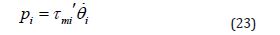
where, i p is the power of individual joints, with mi τ ′ being the transpose of individual joint torques mi τ and i θ being respective joint velocities. It was observed that the peak instantaneous power was observed during Phase 1 ( 140W) as the simulation time was less compared to Phase 2. Based on the individual power requirements, the average of the total power was calculated for the E-Walker’s motion over 1 cycle and it was computed too around 72W . These initial results help to validate the model and the gait controller for walking along a straight line.
It was observed that under these perturbations the performance of the PID-CTC was similar to the non-linear H∞ controller, with insignificant deviations. To understand the robustness of each of these controllers under disturbances of higher magnitude, the following section presents a comparison of the controller performances by evaluating the joint parameter deviations and the system requirements.
Comparison of Controller Performances
To test the robustness of the controller in addition to having a good margin of safety, simulations were run on the E-Walker model with external disturbances ranging up to 1Nm. They are sinusoidal waves with Gaussian random noise of zero means, similar to Figure 7. The performances of the PID-CTC and H∞ controller was analyzed under these perturbations in Figure 9. The joint parameter deviations are recorded over a series of applied disturbances ranging from 10−6 → Nm. Note that 1Nm is an extremely high value of disturbance torque compared to the actual disturbance torques experienced in the Low Earth Orbit. This high value is used in the simulation to test the robustness of the presented controllers.
From Figure 9, it is evident that the performance of the H∞ controller is only slightly better with the increase in perturbations. Figure 9a shows that up to 0.1Nmof external disturbance, both the controllers have similar joint angle deviations, near to zero. However, from 0.1−1Nm, the maximum deviation angle with the PID-CTC is around 0.9 degrees for the LEE, whereas with the H∞ controller it stays around 0.6 degrees. As understood, the H∞ controller only provides a slightly better LEE joint angle tracking ( 0.3 degrees more precise) when compared to the PID-CTC. However, it is to be noted that the LEE deviation is a result of the accumulation of every other joint deviation. The cumulative deviation of all the joints affects the LEE’s final position in the 3D space. It was observed that when PID-CTC was used, the net joint deviations added up to a positional deviation of 2mm in the X axis (direction of motion) of the LEE’s final position. In comparison, the H∞ controller maintains a deviation as low as 0.4mm in the X axis. Deviations in the other axes were significantly low.

Similarly, the joint velocity deviation for both the controllers remains around zero for up to 0.1Nm. However, from 0.1−1Nm, the deviation shoots up to 1.8deg / s with the PID-CTC and remains as low as 0.9deg / s with the H∞ controller (see 9b). Additionally, Figure 9c shows the total average power required during the E-Walker’s motion under external disturbances with both the controllers in the loop. Minimal deviation in total average power ( 0.5W) is observed for both the controllers when the disturbances are around 1Nm.
Figure 10 showcases the control effort of each of the controllers under different acceleration due to gravity (g) values in orbit. Gravitational anomalies exist in space and the simulation takes into consideration g values ranging from 0 −10m / s2 . The torque requirements are plotted alongside different g values. It is seen that up to 1.0m / s2 , the torque requirements are similar. As the g value increases, it is understandable that the PID-CTC controller demands a higher torque, such that under earth-analog conditions (g = 9.81m / s2 ), the torque demand is around 1000Nm more compared to the non-linear H∞ controller.

These results demonstrate that both the non-linear H∞ controller and PID-CTC are suitable controllers for the E-Walker. When compared to the ERA (accuracy: 5mm), the closed-loop accuracy levels of the E-Walker are well within the limits. Under worst case perturbations, it is observed that the H∞ controller offers better robustness when compared to PID-CTC. In conclusion, both controllers are potential candidates to serve as the baseline controller for the E-Walker’s precise tracking of the joint parameters and the decision is ultimately on the user to choose between accuracy and robustness (H∞) or reduced control complexity and less computational effort (PID-CTC).
Conclusions and Future Research
This paper introduced an End-Over-End Walking Robot (E-Walker) with seven Degrees-of-Freedom (DoF) as a potential candidate to perform future in-orbit activities. The choice of the E-Walker is attributed to its capability to enhance its workspace with the capability to walk around. The kinematic and dynamic modelling helped understand E-Walker’s configuration, which helped analyses its gait pattern. For the
Figure 9 control aspect, it was of utmost importance to propose a controller which would help with the precise tracking of the E-Walker’s joint parameters in microgravity. Therefore, the industrially proven and tested PID-CTC and the much-advanced robust nonlinear H∞ controller was designed for the E-Walker’s non-linear dynamic model. The popularity of these controllers in state-of-the-art space missions led to the choice of utilizing them for the E-Walker.
On analysis, the performance of both these controllers was satisfactory and the closed-loop accuracy was much within the levels when compared to conventional in-orbit walking manipulators. On further scrutiny it was found that the accuracy achieved by the H∞ controller was slightly better compared to the conventional PIDCTC, under perturbed conditions given the price of computational effort. Nevertheless, it was concluded that the choice of the controller is ultimately based on the mission requirements. Simulation results of the E-Walker’s successful tracking of the joint parameters were plotted using MATLAB/Simulink. Overall, this paper presents the feasibility of the E-Walker to be integrated into future large-scale space missions requiring high precision and repeatability. The LAST mission involves multiple pick- and-place operations of the mirror modules and the E-Walker is a potential robotic candidate for the mission given its added mobility features and safe manoeuvring capability across the spacecraft platform with the mission payload. Additionally, the seven DoF E-Walker presented would be able to extend the mission lifecycle by carrying out routine maintenance and servicing missions. The E-Walker design shown is versatile, and it is a candidate robot for future planetary or orbital missions. Figure 10
Future research includes simulation-based validation of the E-Walker design with either of the controllers discussed in this paper to carry out any ISAM-based tasks under micro-gravity conditions. Algorithms for collaborative task-sharing between multiple E-Walkers need to be developed to assist with these tasks. Additionally, an Earth-based small-scale E-Walker prototype is being developed at the University of Lincoln for the hardware-inloop validation with the robust controllers in the loop. The prototype would be useful to validate the E-Walkers maneuverability and could be a useful platform to be used for any terrestrial activities.
Acknowledgments
This study is fully funded by the University of Lincoln, UK.
Conflict of Interest
No conflict of interest.
References
- (2021) Catapult: A $1Bn UK Opportunity for In-Orbit Services.
- Oda M, Kibe K, Yamagata F (1996) ETS-VII, Space Robot in-orbit Experiment Satellite. In: Proc. IEEE International Conference on Robotics and Automation, Minnesota, USA 28: 739-744.
- Whittaker W, Urmson C, Staritz P, Kennedy B, Ambrose R (2000) Robotics for Assembly, Inspection, and Maintenance of Space Macrofacilities. In: Proc. AIAA Space Conference and Exposition, California, USA p. 21.
- Yoshida K, Hashizume K, Abiko S (2001) Zero Reaction Maneuver: Flight Validation with ETS-VII Space Robot and extension to Kinematically Redundant Arm. In: Proc. IEEE International Conference on Robotics and Automation, Seoul, South Korea p. 26.
- Friend R (2008) Orbital Express Program Summary and Mission Overview. Proc. SPIE Astronomical Telescopes and Instrumentation, Marseille, France 28: 11-21.
- Li WJ, Cheng DY, Liu XG, Wang YB, Shi WH, et al., (2019) On-Orbit Service (OOS) of Spacecraft: A review of engineering developments. Progress in Aerospace Sciences 108: 32-120.
- Flores-Abad A, Ma O, Pham K, Ulrich S (2014) A Review of Space Robotics Technologies for On-Orbit Servicing. Progress in Aerospace Sciences 68: 1-26.
- Reed BB, Smith RC, Naasz B, Pellegrino J, Bacon C (2016) The Restore-L Servicing Mission. Proc. AIAA Space Conference, Long Beach California, USA.
- Medina A, Tomassini A, Suatoni M, Avil´es M, Solway N, (2017) Towards a Standardized Grasping and Refuelling On-Orbit Servicing for GEO Spacecraft. Acta Astronautica 134: 1-10.
- Jackson L, Saaj CM, Seddaoui A (2020) Downsizing an Orbital Space Robot: A Dynamic System based evaluation. Advances in Space Research 65(10): 2247-2262.
- Romano M (2021) In: Baillieul J, Samad T (eds.) Space Robotics.
- Xu Y (2021) Adaptive Attitude-Tracking Control of Spacecraft considering On-Orbit Refueling. Transactions of the Institute of Measurement and Control 43(6): 1298-1309.
- Seboldt W (2004) Space-and earth-based solar power for the growing energy needs of future generations. Acta Astronautica 55(3): 389-399 New Opportunities for Space. Selected Proceedings of the 54th International Astronautical Federation Congress.
- Whittaker W, Staritz P, Ambrose R, Kennedy B, Fredrickson S, et al., (2001) Robotic assembly of space solar-power facilities. Journal of Aerospace Engineering 14(2): 59-64.
- Taylor B, Aglietti G, Fellowes S, Ainley S, Salmon T, et al. (2018) Remove Debris Mission, From Concept to Orbit. In: Proc. 32nd Annual AIAA/USU Conference on Small Satellites, Utah.
- Wilde M, Harder J, Stoll E (2019) Editorial: On-Orbit Servicing and Active Debris Removal: Enabling a Paradigm Shift in Spaceflight. Frontiers in Robotics and AI 6: 136.
- Nair MH, Rai MC, Poozhiyil M (2022) Design Engineering a Walking Robotic Manipulator for In-Space Assembly Missions. Frontiers in Robotics and AI 9: 995813.
- Lee N, Backes P, Burdick J, Pellegrino S, Fulle C, et al., (2016) Architecture for In-Space Robotic Assembly of a Modular Space Telescope. Journal of Astronomical Telescopes, Instruments, and Systems 2(4).
- Fazekas A (2020) Top 5 Space Station Repair Spacewalk Dangers.
- (2020) Spaceplace.nasa.gov: Why Do We Send Robots to Space? NASA Space Place – NASA Science for Kids.
- Zeleke M (2013) Strategies for Control of Space Robots: A Review and Research Agenda. Global Journal of Researches in Engineering Mechanical and Mechanics Engineering 13: 23-28.
- Dubowsky S, Papadopoulos E (1993) Kinematics, Dynamics, and Control of Free-Flying and Free-Floating Space Robotic Systems. IEEE Transactions on robotics and automation 9(5): 531-543.
- Moosavian SAA, Papadopoulos E (2007) Free-Flying Robots in Space: an Overview of Dynamics Modeling, Planning and Control. Robotica 25(5): 537-547.
- Virgili Llop J, Zagaris C, Richard Zappulla I, Bradstreet A, Romano M (2019) A Convex-Programming-based Guidance Algorithm to Capture a Tumbling Object on Orbit using a Spacecraft Equipped with a Robotic Manipulator. The Inter- national Journal of Robotics Research 38(1): 40-72.
- Virgili-Llop J, Romano M (2019) Simultaneous Capture and Detumble of a Resident Space Object by a Free-Flying Spacecraft-Manipulator System. Frontiers in Robotics and AI 6: 14.
- Seddaoui A, Saaj C (2019) Combined Nonlinear H-infinity Controller for a Controlled Floating Space Robot. Journal of Guidance, Control and Dynamics 42(8): 1878-1885.
- Seddaoui A, Saaj CM, Nair MH (2021) Modeling a Controlled-Floating Space Robot for In-Space Services: A Beginner’s Tutorial. Frontiers in Robotics and AI 8: 725333.
- Nanjangud A, Blacker PC, Young A, Saaj CM, Underwood CI, et al. (2019) Robotic Architectures for the On-Orbit Assembly of Large Space Telescopes. In: Proc. of the Advanced Space Technologies in Robotics and Automation (ASTRA 2019) Symposium, ESA-ESTEC, Noordwijk, Netherlands.
- King D (2001) Space Servicing: Past, Present and Future. In: Proc. of the 6th International Symposium on Artificial Intelligence and Robotics & Automation in Space (i-SAIRAS), Montreal, Canada, June 18-22.
- Gibbs G, Sachdev S (2002) Canada and the International Space Station Program: Overview and Status. Acta Astronautica 51(1-9): 591-600.
- Boumans R, Heemskerk C (1998) The European Robotic Arm for the International Space Station. Robotics and Autonomous Systems 23(1-2): 17-27.
- Cruijssen H, Ellenbroek M, Henderson M, Petersen H, Verzijden P, et al. (2014) The European Robotic Arm: A High-performance mechanism finally on its way to Space. In: Proc. of the 42nd Aerospace Mechanism Symposium, Maryland, USA.
- Letier P, Yan XT, Deremetz M, Bianco A, Grunwald G, et al., (2019) MOSAR: Modular Spacecraft Assembly and Reconfiguration Demonstrator. In: Proc. of the 15th Symposium on Advanced Space Technologies in Robotics and Automation, ESA- ESTEC, Noordwijk, the Netherlands.
- Rodr´ıguez I, Bauer AS, Nottensteiner K, Leidner D, Grunwald G, Roa MA (2021) Autonomous Robot Planning System for In-Space Assembly of Reconfigurable Structures. In: Proc. IEEE Aerospace Conference (Online). pp. 1-17
- (2022) SAS: Walking Manipulator, A reconfigurable mobile manipulator for in- orbit-servicing.
- Nair MH, Saaj CM, Esfahani AG (2020) Modelling and Control of an End-Over- End Walking Robot. In: Towards Autonomous Robotic Systems 128-133.
- Nair MH, Saaj CM, Esfahani AG, Nanjangud A, Eckersley S, Bianco P, et al. (2020) In-space Robotic Assembly and Servicing of High-Value Infrastructure. In: Proc. 71st International Astronautical Federation (IAC), Dubai, October 12 - 16
- Nair MH, Saaj CM, Esfahani AG, et al., (2020) On Robotic in-Orbit Assembly of Large Aperture Space Telescopes. In: IEEE/RSJ International Conference on Intelligent Robots and Systems (IROS), Las Vegas, USA.
- Nair MH, Saaj M, Adlen S, Esfahani AG, Eckersley S, et al. (2020) Advances in Robotic In-Orbit Assembly of Large Aperture Space Telescopes. In: Proc. 15th International Symposium in Artificial Intelligence, Robotics and Automation in Space (i-SAIRAS), Pasadena, USA.
- Astrom K, Hagglund T (1995) PID Controllers: Theory, Design, and Tuning, Second Edition. International Society of Automation.
- Xie YC, Huang H, Hu Y, Zhang GQ (2016) Applications of Advanced Control Methods in Spacecrafts: Progress, Challenges, and Future Prospects. Frontiers of Information Technology & Electronic Engineering 17(9): 841-861.
- Yang CD, Kung CC (2000) Nonlinear H∞ Flight Control of General Six-Degree- of-Freedom Motions. Journal of Guidance, Control, and Dynamics 23(2): 278-288.
- Raffo GV, Ortega MG, Rubio FR (2011) Nonlinear H∞ Controller for the Quad- rotor Helicopter with Input Coupling. IFAC Proceedings Volumes 44(1): 13834-13839.
- Uang HJ, Lien CC (2006) Mixed H2/H∞ PID Tracking Control Design for Uncertain Spacecraft Systems Using a Cerebellar Model Articulation Controller. In Proc. IEEE Control Theory and Applications 153(1): 1-13.
- Huang Y, Jia Y (2016) Nonlinear Robust H∞ Tracking Control for 6 DOF Spacecraft Formation with Input Saturation. In: In Proc. 55th IEEE Conference on Decision and Control, Las Vegas, USA.
- Spong MW, Vidyasagar M (2020) Robot Dynamics and Control, 2nd (edn.) John Wiley & Sons.
- Yusof, R, Omatu S, Khalid M (1994) Self-tuning PID Control: A Multivariable Derivation and Application. Automatica Vol. 30(12): 1975–1981.
- Mao Q, Dou L, Zong Q, Ding Z (2017) Attitude Controller Design for Reusable Launch Vehicles during reentry phase via Compound Adaptive Fuzzy H-infinity Control. Aerospace Science and Technology 72: 36-48.
- Chen BS, Lee TS, Feng JH (1994) A Nonlinear H-infinity Control Design in Robotic Systems under Parameter Perturbation and External Disturbance. International Journal of Control 59(2): 439-461.
- Ata AA (2007) Optimal trajectory planning of manipulators: a review. Journal of Engineering Science and Technology 2(1): 32-54.
- Zag´orski P (2012) Modelling Disturbances Influencing an Earth-Orbiting Satellite. Pomiary Automatyka Robotyka 16: 98-103.
- Hollot CV, Looze DP, Bartlett AC (1990) Parametric Uncertainty and Unmodeled Dynamics: Analysis via Parameter Space Methods. Automatica 26(2): 269-282.
-

This work is licensed under a Creative Commons Attribution-NonCommercial 4.0 International License.


