


 Research Article
Design, Prototyping, And Evaluation of a Custom Unmanned Ground Vehicle Drive Elements
Received Date: October 21, 2025; Published Date: November 03, 2025
Abstract
This paper presents the development of a modular unmanned ground vehicle platform designed for integration into heterogeneous robotic systems. The focus is on the design, prototyping, and testing of drive configurations capable of operating on uneven terrain while supporting future multirotor unmanned aerial vehicles docking and battery swapping modules. Two differential-drive configurations, wheeled and tracked, were investigated to assess mobility. Insights from this comparative evaluation informed the design of a custom drive assembly with modular drive wheels and integrated mechanical and electrical components. Prototyping and testing of the custom modular drive system assembly confirmed reliable torque transfer, smooth operation, and ease of maintenance. The results demonstrate an effective approach for developing robust, scalable, and adaptable ground platforms suitable for cooperative missions.
Keywords:Heterogeneous Robotic System; Unmanned Ground Vehicle; Differential Drive; Custom Drive Elements
Introduction
The rapid development of mobile robotics and artificial intelligence has significantly expanded the range of applications of autonomous systems across industries such as inspection, logistics, agriculture, and infrastructure maintenance. Among various robot types, ground, aerial, and maritime, unmanned ground vehicles (UGVs) and unmanned aerial vehicles (UAVs) have attracted particular attention due to their complementary capabilities. UAVs provide a wide operational perspective, fast data acquisition, and access to hard-to-reach areas, while UGVs offer high payload capacity, longer operational endurance, and stable ground-level sensing.
Heterogeneous robotic systems that integrate aerial and ground platforms combine the advantages of both domains, enabling coordinated missions such as mapping, monitoring, and autonomous inspection. In such systems, UAVs perform rapid aerial data collection and provide situational awareness from an elevated perspective, while UGVs serve as mobile ground bases, supporting transport, recharging, or battery replacement. This cooperative interaction improves autonomy, efficiency, and safety, particularly in environments that are unstructured or hazardous for human access. Several studies have demonstrated the effectiveness of UAV– UGV cooperation in diverse applications. In paper [1], a ground robot and a quadrotor jointly explored indoor environments, where the multirotor UAV provided a real-time bird’s-eye perspective to enhance situational awareness and navigation. Similarly, the work on Autonomous Inspection [2] proposed a cooperative control architecture for power line inspection, ensuring mutual localization and safe distance maintenance between aerial and ground vehicles during high-precision inspection tasks. Furthermore, an integrated system for construction data collection [3] showed the potential of such systems in large-scale environments, where the UAV provided visual feedback and mapping capabilities, supporting the UGV in navigating cluttered construction areas. These examples underline the flexibility and scalability of heterogeneous robotic systems in addressing complex real-world missions across various domains.
Recent research has increasingly focused on extending the autonomy of heterogeneous UAV–UGV systems through the development of reliable docking, charging, and battery replacement mechanisms. One of the central challenges is achieving precise and robust UAV landing on static or moving UGV platforms under real-world disturbances. Vision-based and sensor fusion methods have proven particularly effective for accurate localization and trajectory control. For instance, a dynamic landing strategy presented in [4] demonstrated a vision-guided approach for quadrotor landing on a moving platform. Similarly, an autonomous VTOL-UAV docking system proposed in [5] employed a mobile manipulator equipped with visual tracking to establish stable air– ground contact, enabling on-site energy replenishment. Building upon these advances, cooperative UAV–UGV docking frameworks have also been developed to support autonomous charging and battery replacement. A vision-based system introduced in [6] utilized multi-scale fiducial markers to guide high-precision UAV landing on a mobile UGV, even in GPS-denied environments. Such systems commonly integrate passive or mechanical alignment aids, contact-based or wireless charging interfaces, and robotic battery swapping modules, forming the foundation for long-endurance heterogeneous robotic missions with minimal human intervention.
Within this context, this paper focuses on the development of a modular UGV platform as part of a heterogeneous UGV-UAV system. The primary goal is to design and evaluate drive configurations capable of operating on uneven terrain, supporting the future integration of a UAV docking and battery swapping module. To this end, two differential-drive UGV prototypes, a wheeled and a tracked configuration, were designed, fabricated, and experimentally tested. The choice of locomotion type directly influences the robot’s mobility, stability, and energy efficiency, particularly in unstructured outdoor environments. As highlighted in [7], tracked systems offer superior traction and ground adaptability on soft or irregular terrains due to their larger contact surface, though typically at the expense of higher energy consumption and reduced speed compared to wheeled systems. Building on the insights gained from this comparative evaluation, the study presents the design of a custom drive assembly for integration within the final heterogeneous robotic platform.
Design Considerations for UGV Drive Configuration
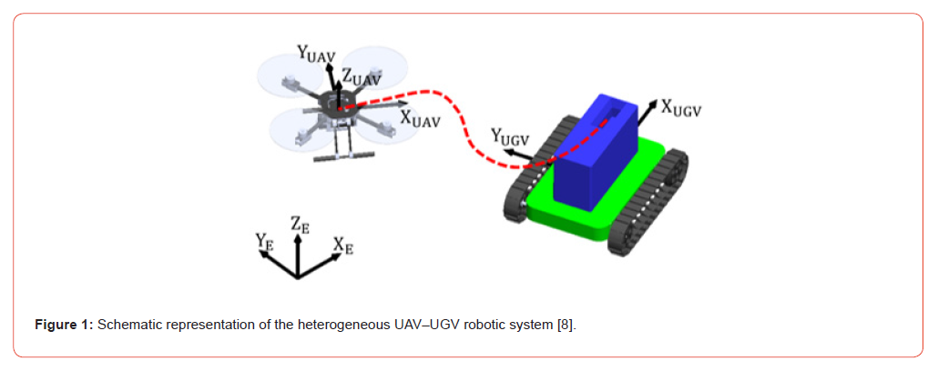
A heterogeneous ground–aerial system consisting of one UGV and one multirotor UAV enables tasks such as surveillance, mapping, inspection, and reconnaissance. The multirotor UAV provides an aerial perspective and high-resolution data collection, while the UGV serves as the ground component, offering mobility, ground-level sensing, and the capability to transport equipment. Wireless communication links allow real-time data exchange and coordinated operation between the aerial and ground units, with the base station providing mission planning and control interfaces. Figure 1 schematically illustrates the considered heterogeneous robotic system. The goal of the project is to develop a multipurpose UGV capable of operating in outdoor environments and performing a variety of missions. Within the cAMGARS project framework, a key requirement is the integration of a robotic system for battery replacement of multirotor UAVs, enabling semi-autonomous battery swapping and ensuring continuous operation of the heterogeneous system. Before the project implementation, preliminary studies were conducted to evaluate feasible UGV drive configurations. As part of this investigation, two differential-drive prototypes were developed for outdoor operation on uneven terrain, providing insights into mechanical design and integration with heterogeneous robotic systems.
Wheeled UGV Configuration
Differential drive is one of the most common configurations in mobile robotics, applied across a wide range of systems, from small educational robots [9, 10] to complex outdoor vehicles, due to its mechanical simplicity and intuitive control principle. In such a configuration, the vehicle typically consists of two independently actuated drive sides, each with a wheel or track element, enabling rotation in place without translational motion. The robot’s heading angle is controlled by varying the angular velocities of the left and right actuators, while synchronous rotation of both sides results in straight-line motion. Differential drive robots belong to the class of non-holonomic systems, which do not allow independent control of all degrees of freedom, requiring coordinated actuation to achieve desired maneuvers. The kinematics of this configuration are often described using a Unicycle-Type Wheeled robot model [11], where the translational and rotational velocities of the vehicle are functions of the left and right actuator velocities, and the system can be controlled using straightforward inverse kinematics mapping. This simplicity, combined with reliable maneuverability, makes differential drive a suitable choice for scalable UGV prototypes alike.
The first UGV prototype is a four-wheel differential drive platform designed primarily for mobility testing and validation of the drive concept. The vehicle consists of two independently driven sides, each actuated by a DC motor with gearbox. Straightline motion is achieved with synchronous wheel rotation, while rotation in place occurs when wheels on opposite sides rotate at different speeds. A chain drive system was implemented between each motor and its pair of wheels, with double sprockets ensuring synchronous rotation. A sprocket ratio of 10:32 was selected to provide sufficient torque, resulting in a nominal translational speed of approximately 2 m/s at a motor speed of 309 RPM and torque of 13 Nm. Bearings (UCFL204) mounted in adjustable supports enable proper chain tensioning and smooth rotation. The CAD model of one side of the differential drive assembly is shown in Figure XY, illustrating the arrangement of the motor, gearbox, chain drive, sprockets, and wheel supports.
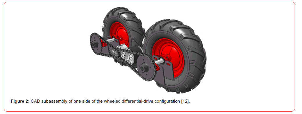
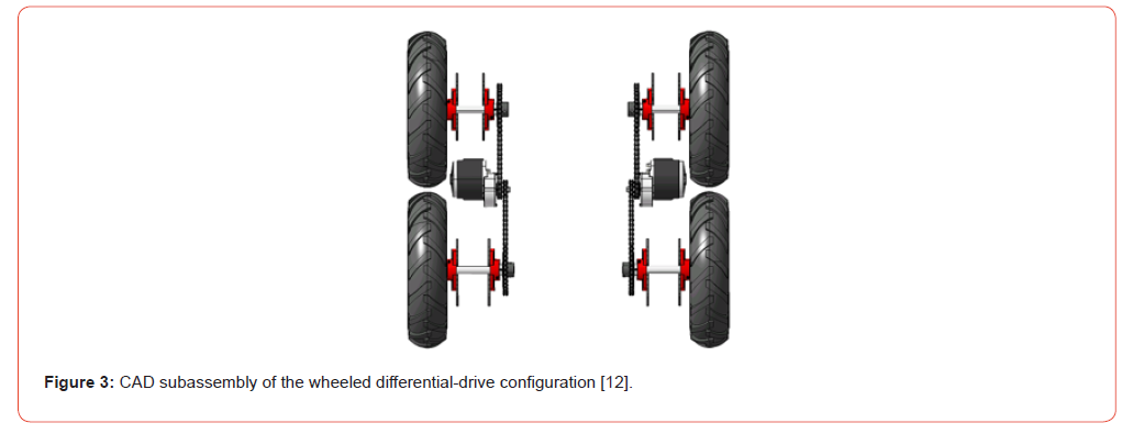
This differential drive configuration was subsequently adapted as the propulsion module for a robotic lawn mower, demonstrating its versatility and scalability for various mobile robotic applications. Pneumatic tires (Ø 400 mm, width 100 mm) provide traction and damping on irregular terrain. This configuration offers simplicity, cost efficiency, and ease of maintenance, making it suitable for initial prototyping and scalable testing. The overall differential drive layout, including the geometric arrangement of the propulsion elements, is illustrated in the CAD model shown in Figure 3.
Tracked UGV Configuration
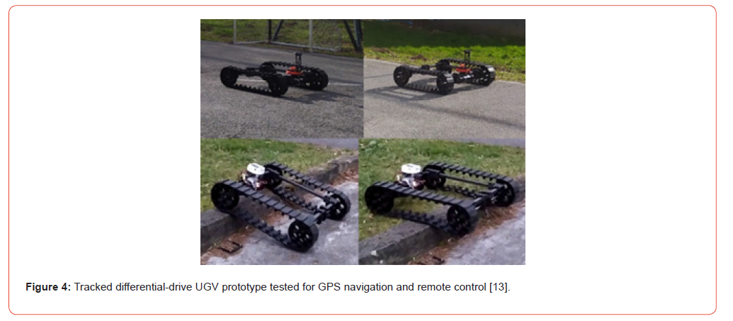
The second configuration employed a differential tracked drive system to enhance terrain adaptability and modularity for outdoor operation. The UGV chassis consists of a welded steel profile frame onto which the drive modules are symmetrically mounted, one on each side. Each drive module includes a pair of molded rubber tracks and two types of wheels: a powered drive wheel and a free (idler) wheel. The drive wheel is connected to a DC motor via a sprocket–chain transmission, while the idler wheel rotates freely on a shaft with integrated bearings to maintain track alignment and tension. This differential arrangement allows independent control of the left and right tracks, enabling both straight-line motion and rotation in place. For the tracked prototype, a pair of 24 V DC gear motors (IG52-04, 285 RPM) controlled by a Sabertooth dual 25 A motor driver were used. Torque was transmitted from the motor to the drive wheel through a 15-tooth motor sprocket, an ANSI #25 roller chain, and a 25-tooth sprocket on the drive wheel shaft. Both drive and free wheel shafts were supported by bearings mounted on frame parts connected to the chassis, providing structural stability and allowing independent track tensioning.
Parts for the drive module were produced using a combination of subtractive and additive manufacturing technologies. Components subjected to significant loads were fabricated from high-strength materials, while non-critical parts were produced using rapid prototyping for iterative design evaluation. The modular nature of the platform allowed for separate testing of the individual drive elements, track components, and motor integration. The testing process began with verification of track rotation to ensure proper alignment and smooth motion. Subsequently, the motor and driver system was tested to confirm reliable torque transmission and responsive control. Following this, the UGV was operated via remote control to assess manual maneuverability. GPS-based navigation tests were then conducted to evaluate positioning accuracy and autonomous path-following capabilities. Finally, the system was tested in obstacle negotiation scenarios to verify traction, stability, and overall performance on uneven terrain. These tests are illustrated in Figure 4.
Comparative Discussion and Design Implications
Both the wheeled and tracked differential-drive UGV configurations proved functional and provided valuable insights for the development of a multipurpose ground vehicle. The wheeled platform offered simplicity, lower cost, and ease of maintenance. It employed commercially available wheels and tires, which were inexpensive and readily sourced but limited in terms of customization. The motors and drivers were also cost-effective and widely available, making this configuration suitable for rapid prototyping and scalable testing.
The tracked configuration, on the other hand, offered superior off-road performance, enhanced traction, and greater maneuverability on uneven terrain. It enabled more extensive customization of the drive module, including custom drive wheels and tailored mechanical components. However, it required highercost motors, motor drivers, and molded rubber tracks, increasing both procurement and assembly complexity. Insights from both prototypes informed the design of the new multipurpose UGV: the tracked system’s robust terrain performance was adopted as the baseline, while cost-effective and readily available electrical components from the wheeled configuration were incorporated. This approach led to the modular differential-drive propulsion system with custom drive elements described in Section 3.
Design of Custom Drive Assembly
The development of the new UGV configuration within the cAMGARS project places a strong emphasis on modularity, compactness, and scalability of the drive system. Unlike previous platforms that relied on commercially available drivetrain components, the current iteration introduces several customdesigned mechanical elements to improve load distribution, ease of maintenance, and manufacturing adaptability. The differential drive configuration of the UGV platform consists of a chassis onto which the drive elements are symmetrically integrated. The vehicle employs two independent drive modules, one on each side, each composed of a continuous rubber track, mechanical transmission components, a drive motor, and a motor driver. This configuration enables differential steering through independent control of the left and right drive assemblies, ensuring maneuverability and traction across varied terrain conditions.
Drive Assembly Component Selection
The design of the UGV’s drive assembly was initiated based on the selection of commercially available rubber tracks, which defined the key geometric and functional parameters of the propulsion system. The selected rubber tracks feature a pattern that provides traction across a variety of terrain types while maintaining flexibility for turning maneuvers. Their internal tooth geometry and pitch spacing directly influenced the design of the custom drive wheel, particularly the torque-transmitting pocket features described in the following subsection. Consequently, all mechanical and electromechanical components of the drive assembly were chosen and dimensioned to ensure full compatibility with these tracks and to achieve smooth, synchronized motion during operation.
The mechanical elements of the drive assembly were selected to provide structural integrity, reliable torque transmission, and seamless integration with the custom drive wheel. A stainless-steel solid round rod (10 mm diameter, 200 mm length) serves as the drive wheel axle, ensuring sufficient stiffness under operational loads. Radial ball bearings (6001 series, 28 × 12 × 8 mm) are employed to support smooth rotation of the drive wheel and minimize friction. Torque is transmitted from the motor to the wheel via a 410-series chain and a 28-tooth sprocket, both selected for their compatibility and durability under variable load conditions. These mechanical components are integrated with the custom-designed drive wheel parts to form a scalable and manufacturable propulsion system.
The drive system is powered by a 24 V DC brushed electric motor, selected from the manufacturer VEVOR due to its availability, cost efficiency, and wide product range. The motor provides 350 W of output power at a rated speed of 3000 RPM and operates at a rated current of 18.4 A. It features a 410-9T sprocket and an integrated 9.7:1 gear reduction, enabling reversible rotation and precise torque transfer to the drive wheel through the chain–sprocket system. Motor control is implemented using a high-power motor driver (BTS7960, 43 A), which provides bidirectional speed control, current limiting, and thermal protection. The driver employs dual H-bridge circuits based on Infineon BTS7960 chips, offering strong drive and braking performance while isolating the microcontroller from high-current loads. The module requires only four control lines for power and PWM inputs, simplifying integration with the embedded control system.
Together, the selected mechanical and electrical components form a robust and integrated drive subsystem that ensures compatibility with the custom drive wheel assembly and reliable operation of the overall UGV platform.
Design of Custom Drive Wheel Assembly
The fully custom drive wheel assembly was developed to meet the mechanical and geometric requirements of the UGV platform. The design focuses on four custom parts: the drive wheel itself, which is divided into an inner and an outer part for manufacturing and assembly purposes; a custom adapter part mounted on the wheel axle, which serves as an interface for the bearings and prevents axial translation of the wheel; and the sprocket wheel flange, which enables mounting of the wheel sprocket. Although the drive wheel is conceptually a single part, it is split into two sections to facilitate assembly, integration of bearings, and fastening of mechanical interfaces. All custom components are intended for fabrication using additive manufacturing technologies, requiring the CAD model to be specifically tailored to the constraints and capabilities of these production methods. This approach allows the creation of complex geometries that ensure effective torque transmission, while minimizing material usage and maintaining precise alignment of mating parts. This section describes in detail the 3D modeling process, the generation of torque-transmitting features, and the assembly preparation steps, culminating in a fully integrated drive wheel subassembly suitable for installation in the UGV drivetrain.
The 3D modeling process of the drive wheel was conducted using a parametric design approach within the SolidWorks CAD environment. In the initial step, a solid cylinder with a diameter of 169 mm and a width of 50 mm was extruded to define the wheel’s base geometry.
In the first phase of the modeling process, features responsible for torque transmission between the drive wheel and the selected track (caterpillar) element were developed. The sequence of CAD operations was defined as follows:
• Extruded Cut – an initial volume removal was performed
on the base cylindrical body to generate the pocket geometry
that ensures mechanical coupling with the track element;
• Circular Pattern – the previously created pocket feature
was replicated circumferentially to form nine uniformly spaced
pockets, ensuring geometric symmetry and uniform torque
transfer;
• Revolved Cut – additional volume was removed around
the central wheel axis to refine the inner profile and reduce
unnecessary mass;
• Mirror – finally, the patterned and revolved features were
mirrored to the opposite side of the wheel, resulting in a fully
symmetric geometry optimized for bidirectional operation and
consistent load distribution.
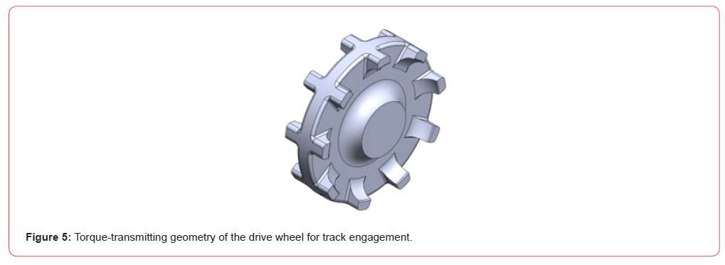
This sequence of modeling operations defines the torquetransmitting geometry between the drive wheel and the track element, as illustrated in Figure 5.
In the second phase of the modeling process, additional features were developed to prepare the model for assembly integration and to enable the installation of components responsible for wheel rotation and torque transmission from the drive motor through the chain system. To achieve this, an additional solid volume was introduced to define a mounting interface for the drive sprocket. Subsequently, a Revolved Cut operation was executed around the wheel’s central axis to remove volume and create the seating geometry for the bearings and the wheel axle. To facilitate manufacturing and assembly, the drive wheel was divided into two separate parts-an inner and an outer section. These two sections are joined during assembly using mechanical fasteners. Two connection zones were defined: in the central zone, the outer and inner wheel parts are connected using M4 extended nuts and socket head screws, while in the outer zone, the wheel halves are secured using M3 socket head screws and self-locking nuts. Corresponding pockets were modeled to ensure accurate alignment, structural rigidity, and ease of assembly. Finally, fillets were applied wherever geometrically and structurally appropriate to eliminate sharp edges and improve stress distribution. The resulting 3D model of the custom-designed drive wheel assembly, integrating both custom and standard mechanical components, is shown in Figure 6.
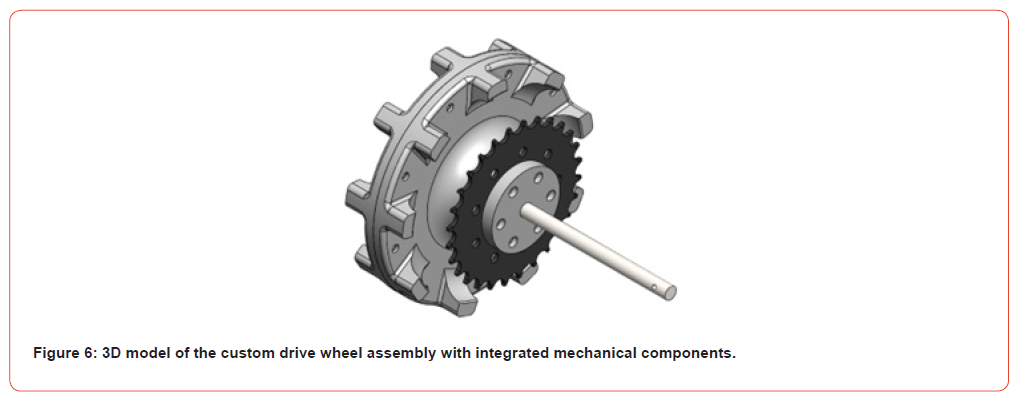
To complete the drive wheel assembly, the following mounting sequence has to be implemented: a standard stainless steel solid round rod serves as the wheel axle. A custom adapter part is first mounted onto the axle to interface with the bearings. Subsequently, a bearing is installed into the outer drive wheel part, and M4 extended nuts are inserted into the inner drive wheel part. Next, the outer and inner drive wheel parts are fastened together using M3 screws and self-locking nuts in the outer zone. The axle with the custom adapter is then inserted, followed by placement of a second bearing within the custom sprocket wheel flange. Finally, the sprocket and flange are mounted onto the inner drive wheel part and secured with screws in the central zone. This procedure results in a fully integrated drive wheel assembly, ready for installation in the UGV drivetrain.
Differential Drive Assembly
The complete drive assembly of the UGV consists of a pair (left and right) of drive modules, each corresponding to one side of the vehicle. Each module includes a powered drive wheel assembly and a non-powered (idler) wheel, which together support and guide the continuous rubber track. In this configuration, the rotation of the drive wheel drives the track motion, while the idler wheel maintains track alignment and tension. Differential steering is achieved by independently controlling the rotational speed and direction of the drive motors on each side, allowing the UGV to perform forward, reverse, and pivot turns. The non-powered wheel was designed following the same modeling principles introduced in Section 3.2, ensuring full compatibility with the selected track geometry. However, unlike the drive wheel, the idler wheel does not include an integrated sprocket and sprocket flange. It retains only the bearing–axle interface, allowing free rotation while maintaining axial alignment and track tension. Both wheel axles are fixed to the robot chassis to ensure structural rigidity and consistent track alignment during motion.
Each drive module is mounted onto a dedicated side frame, which supports the DC motor and serves as the structural base for the wheel axle. The frame also integrates an adjustable tensioning mechanism that maintains optimal track tension and facilitates track installation or removal during maintenance. In the prototype phase, these structural components are manufactured using rapid prototyping technologies to allow iterative design adjustments and testing. Once the final geometry and load-bearing requirements are validated, the components will be fabricated from aluminum using conventional subtractive manufacturing processes to achieve improved mechanical strength, dimensional accuracy, and durability. This modular differential drive architecture ensures reliable traction, simplified maintenance, and adaptability for future optimization of the UGV’s mobility system.
Prototyping and Testing
The prototyping phase of the UGV platform enabled iterative evaluation of the modular drive assemblies and facilitated adjustments before final production. The final UGV prototype will be fabricated using a combination of additive manufacturing (AM) technologies for polymer components and conventional subtractive machining for aluminum parts. Additive manufacturing will enable the production of complex geometries and modular components from polymer materials, allowing rapid iteration and customization, while aluminum parts will ensure high-strength structural elements with precise tolerances for critical load parts.
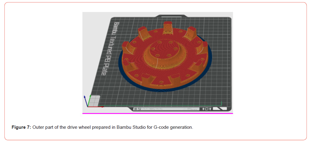
For the additive manufacturing of polymer components, Fused Deposition Modeling (FDM) AM technology was selected due to its accessibility, cost-effectiveness, and suitability for producing structural elements that do not require extremely high mechanical performance. The material chosen for FDM printing was PETG, which offers a favorable balance of strength, flexibility, and thermal resistance, making it suitable for modular components exposed to moderate loads and outdoor operations. The printing hardware employed consisted of Bambu Lab P1S and A1 Mini printers, providing reliable precision and repeatability across different component sizes. Printing preparation and workflow management were carried out using Bambu Studio software, enabling optimized slicing, orientation, and support generation. The methodology for part fabrication follows the framework for design and additive manufacturing of specialized UAV parts described in [14]. This structured approach ensures that printed components are functional, customizable, and compatible with subsequent assembly and testing. Figure 7 illustrates the outer part of the drive wheel prepared in Bambu Studio slicer, ready for generating the G-code that will be executed on the Bambu P1S 3D printer.
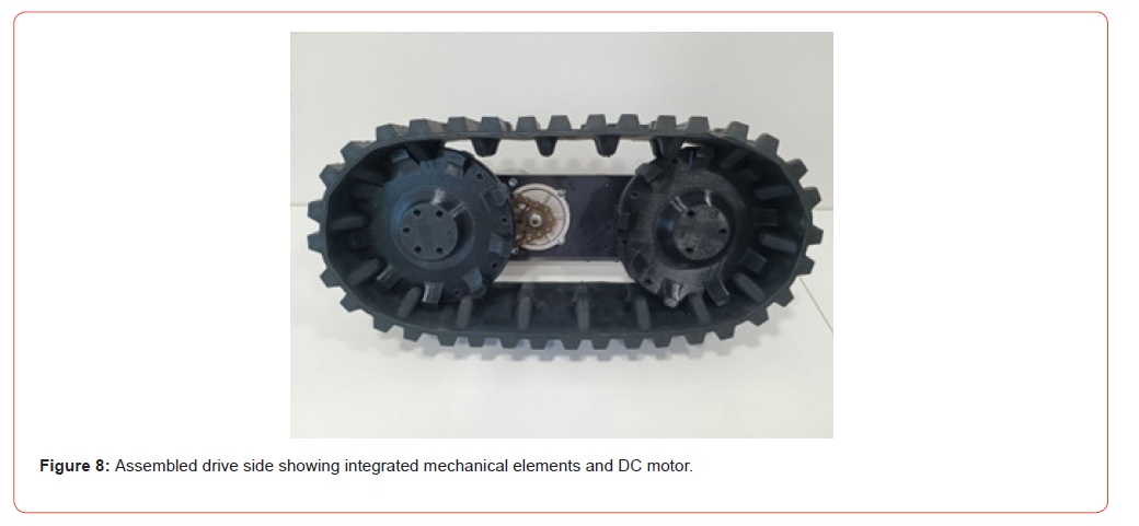
The modular nature of the platform allowed individual testing of each subsystem, accelerating development and enabling distributed fabrication. Initial tests focused on the drive elements and track components of the differential-drive module. For 3D-printed parts, a post-processing phase was performed to remove support material where applicable, ensuring clean surfaces and dimensional accuracy. The printed custom components were then assembled together with the mechanical elements of the drive system, forming complete drive wheel subassemblies. Track alignment, tensioning, and rotation driven by the integrated drive wheel were evaluated. Additional tests were conducted for track removal and reinstallation to verify ease of maintenance and repeatable performance. Following successful track testing, the DC motors and chain transmissions were installed and examined to confirm reliable torque transfer, smooth operation, and responsive actuation under controlled conditions. The assembled drive side, including mechanical elements and DC motor, is shown in Figure 8. Subsequent integration of the motors and drive modules allowed preliminary validation of the full drive system under remote control, providing confidence in the performance and robustness of the modular UGV platform.
Conclusion
This study presented the design, prototyping, and testing of a modular unmanned ground vehicle (UGV) platform intended for integration into heterogeneous UAV-UGV systems. Two differential-drive configurations, wheeled and tracked, were evaluated to assess mobility and terrain adaptability. Insights from the comparative evaluation informed the development of a custom drive assembly with modular drive wheels and integrated mechanical and electrical components. The prototyping and testing phase, including AM of polymer parts and integration with DC motors and chain transmissions, confirmed reliable torque transfer, smooth operation, and ease of maintenance. The modular architecture enables for rapid iteration, distributed fabrication, and future scalability, supporting the integration of UAV docking and battery-swapping modules. Overall, the results demonstrate a practical approach to developing robust, adaptable, and scalable ground platforms capable of performing cooperative missions in unstructured and challenging environments, providing a foundation for extended autonomy in heterogeneous robotic systems.
Acknowledgement
This research was funded and supported by the European Union through the project “Advancing Autonomy: A Concept for a Multipurpose Ground-Aerial Robotic System (cAMGARS)” (Grant Agreement ID: NPOO.C3.2.R3-I1.05.0357).
Conflict of Interest
None.
References
- S Hood, K Benson, P Hamod, D Madison, J M O'Kane, et al. (2017) Bird's eye view: Cooperative exploration by UGV and UAV. 2017 International Conference on Unmanned Aircraft Systems, Miami, FL, USA, pp. 247-255.
- A Cantieri, M Ferraz, G Szekir, M Antônio Teixeira, J Lima, et al. (2020) Cooperative UAV-UGV Autonomous Power Pylon Inspection: An Investigation of Cooperative Outdoor Vehicle Positioning Architecture. Sensors 20(21): 6384.
- K Asadi, AK Suresh, A Ender, S Gotad, S Maniyar, et al. (2020) An integrated UGV-UAV system for construction site data collection. Autom. Constr 112: 103068:1-103068:23.
- Paris A, Lopez BT, How JP (2020) Dynamic Landing of an Autonomous Quadrotor on a Moving Platform in Turbulent Wind Conditions. 2020 IEEE International Conference on Robotics and Automation (ICRA), Paris, France, pp. 9577-9583.
- Narváez E, Ravankar AA, Ravankar A, Emaru T, Kobayashi Y (2021) Autonomous VTOL-UAV Docking System for Heterogeneous Multirobot Team. IEEE Trans. Instrum. Meas 70: 1-18.
- Niu G, Yang Q, Gao Y, Pun MO (2021) Vision-based Autonomous Landing for Unmanned Aerial and Mobile Ground Vehicles Cooperative Systems. IEEE Robot. Autom. Lett pp. 1.
- Bruzzone L, Nodehi SE, Fanghella P (2022) Tracked Locomotion Systems for Ground Mobile Robots: A Review. Machines 10: 648.
- D Kotarski, A Scuric, N Krznar (2025) Mechanism Design for Battery Swapping in a Heterogeneous Robotic System, 6th International Conference in Electronic Engineering & Information Technology (EEITE), Chania, Greece pp.1-6.
- Piljek P, Kotarski D, Šćuric A, I Petanjek T (2023) Prototyping and Integration of Educational Low-Cost Mobile Robot Platform. Tehnički glasnik 17 (2): 179-184.
- Kotarski D, Piljek P, I Šančić T (2025) Design and Development of Educational Modular Mobile Robot Platform. Tehnički glasnik 19 (1): 1-8.
- Kim BM, Tsiotras P (2002) Controllers for Unicycle-Type Wheeled Robots: Theoretical Results and Experimental Validation. IEEE Transactions on Robotics and Automation 18(3): 294-307.
- De Bona, MI Kotarski D (2025) Designing and Prototyping of a Hybrid Robotic Lawnmower. Tehnički glasnik 19(1): 166-172.
- Kotarski D, Šančić T, De Bona M, Piljek P (2023) Unmanned ground vehicle as a docking element of a ground-aerial robotic system. IntechOpen.
- Piljek P, Krznar N, Krznar M, Kotarski D (2022) Framework for Design and Additive Manufacturing of Specialised Multirotor UAV Parts. IntechOpen.
-

This work is licensed under a Creative Commons Attribution-NonCommercial 4.0 International License.