 Research article
Corrected Internal Torques of Gyroscopic Effects
Ryspek Usubamatov*
Department of Transport and Manufacturing Engineering, Kyrgyz State Technical University, Kyrgyzstan
Ryspek Usubamatov, Department of Transport and Manufacturing Engineering, Kyrgyz State Technical University, Kyrgyzstan.
Received Date: March 10, 2022; Published Date: March 21, 2022
Abstract
The dynamics of the rotating objects is the complex piece of the classical mechanics which example presented by gyroscopic effects. Researchers study gyroscope problems during the centuries and obtained not comforting analytical results. The physics of gyroscopic effects does not have an adequate description. The recent investigation finally solved the gyroscope problems in principle but some mathematical models for gyroscopic inertial torques contained mechanical errors. The corrected gyroscope theory opened breakthrough directions in the solutions to dynamics of rotating objects. This publication presents a summation of the gyroscope theory that gives a general presentation of its principal parts.
Keywords: Gyroscopic devices; Gyroscope theory
Introduction
The gyroscopic effects are the most compound and attractive part of the dynamics of rotating objects in engineering [1-4]. Beginning with the Industrial Revolution, scientists of the entire world tried to find a mathematical model for gyroscopic effects and describe their physics. Researchers of the past centuries who did not know the several principles of the physical laws of matter could not solve this problem in principle. They developed only partially and simplified analytical models. The gyroscopic effects are based on the principles of classical mechanics that were discovered for the time of two hundred years from the middle of the 17 century. The researchers of the following centuries could not combine the principles of mechanics for the solution of the gyroscopic effects. For the practical applications of gyroscopic devices, they developed numerical modeling and simplified theory for the educational processes [5-7]. These unresolved problems present a challenge to new researchers, which today publish many works related to the dynamic of rotating objects [8-10].
The latest investigations discovered and mathematically described the physics of gyroscope effects, which are a manifestation of the action of the system of several interrelated inertial torques generated by the rotating mass. The new segments of knowledge formulated the fundamental principles of gyroscope theory that presented by the centrifugal, Coriolis forces, the change in the angular momentum, and the ratio of the angular velocities of the gyroscope about their axes of motions. The new method for deriving mathematical models for inertial torques produced by masses of rotating objects can be applied to any rotating objects of different designs [11,12]. It can be a spinning disc, cylinder, ring, cone spheres, paraboloid, propeller, etc., and nonsymmetrical objects.
The new gyroscope theory contains complex mathematical models that have some incorrect processing. The errors are mechanical and not principle [13,14]. The any innovations are accompanied by successes and failures, but after corrections are finally accepted. This summary presents the fundamental properties of the spinning disc mathematically formulated and validated by practical tests. The worked-out result brings a significant impact to the gyroscope theory and opens a new direction in the chapter of dynamics of classical mechanics.
Methodology
The physics of gyroscopic effects shows the external torque acting on the spinning objects, yields the system of inertial torques generated by the one rotating mass. The system contains the eight inertial torques of interrelated action, about two axes of the spinning objects and generated by the following inertial forces:
• Centrifugal forces of the rotating masses that produce resistance and precessed inertial torques
• Coriolis forces are a product of the tangential velocity of rotating masses and the precessed angular velocity of the turn of the disc that produces the resistance inertial torque.
• The change in the angular momentum that is the precessed inertial torque
The two resistance and two precession torques are acting about each axis. All inertial torques are interrelated by the ratio of the angular velocities of the spinning objects about axes of rotation.
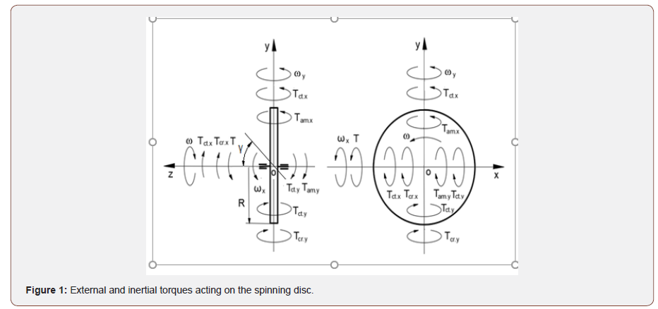
The action of the external and inertial torques on the spinning disc is shown in Figure 1.

Where T is the external torque, Tct.i,Tcr.i,Tam.i,are the inertial torques generated by the centrifugal, Coriolis force and the change in the angular momentum acting about axis i respectively; ω, wx,- wyare the angular velocity of the dis about axis oz, ox and oy, respectively; R is the radius of the disc, and γ is the angle of the inclination of the disc axle.
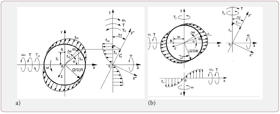
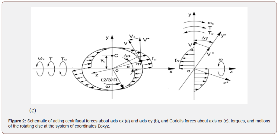
The action of the inertial torques, generated by the distributed rotating mass elements presented in Figure 2.


Where m is the mass element of the disc; ω is the constant angular velocity of the disc; α is the angle of the mass element’s disposition; Δyis the angle of turn for the disc’s plane sinΔy = Δyfor the small values of the angle); ym = (2.3)Rsin m α and xm = (2.3)Rcosα is the distance of the mass element’s location relative to axes ymand xm, respectively, fct.i, fct.i, fam.i.are the components of the centrifugal, Coriolis force and the change in the angular momentum acing about axis i, respectively; T, Tct, TcrTamis the external and inertial torques respectively; V is the tangential velocity of the mass element; A, B, C is the centroids.
The mathematical models for inertial torques and the dependency of the angular velocities for the precessions of the spinning disc about axes are presented in Table 1.
Table 1: Inertial torques of the spinning disc and the dependency of the angular velocities of the precessions.

Where ωi is the angular velocity of gyroscope rotation about axis i; ω is the angular velocity of the spinning disc about axis oz; J is the mass moment of inertia of the spinning disc; γ is the angle of disposition. The turn of the spinning disc of horizontal disposition about axis ox is active by the dependency until its turn about axis oy on the angle. It is demonstrated on the gimbal motions of the laboratory gyroscope. The following turn of the outer gimbal does not lead to the turn of the inner gimbal with the spinning disc.
Figure 3 shows the change in the angular disposition φ about axis oy of the precessed motion versus the change in the angular disposition γ about axis ox.

The diagram demonstrates the gyroscope precessions validated by the practical tests.
Conclusion
The gyroscopic effects were quite complex physical and mathematical problems for a long time. The known publications related to gyroscopic effects contain many simplifications and assumptions and do not respond to the engineering practice. This is an unusual phenomenon in science of the classical mechanics, which methods can solve more complex problems. A recent study of the gyroscopic effects finally solved this old task in principle. Some mathematical models for the gyroscopic effects were published with errors in the complex analytical processing of inertial torques that are now corrected. The new methods of gyroscope theory open a new chapter in the dynamics of the rotating object of classical mechanics. Engineering receives a new analytical approach for solving gyroscopic effects. The corrected inertial torques of gyroscope theory can be useful in practice and present a good example for education processes.
Acknowledgement
None.
Conflict of Interest
No Conflict of interest.
References
- Hibbeler RC, Yap KB (2013) Mechanics for Engineers-Statics and Dynamics, 13th ed. Prentice-Hall, Pearson, Singapore.
- Gregory DR (2006) Classical Mechanics, Cambridge University Press, New York.
- Taylor JR (2005) Classical Mechanics, University Science Books, California, USA.
- Aardema MD (2005) Analytical Dynamics. Theory and Application. Academic/Plenum Publishers, New York.
- Cordeiro FJB (2015) The Gyroscope, Createspace, NV, USA.
- Greenhill G (2015) Report on Gyroscopic Theory, Relink Books, Fallbrook, CA, USA.
- Scarborough JB (2014) The Gyroscope Theory and Applications, Nabu Press, London.
- Weinberg H (2011) Gyro Mechanical Performance: the most important parameter. Analog Devices, Technical Article MS-215 8: 1-5.
- Liang WC, Lee SC (2013) Vorticity, gyroscopic precession, and spin- curvature force. Phys Rev D 87: 044024.
- Crassidis JL, Markley FL (2016) Three-Axis Attitude Estimation Using Rate-Integrating Gyroscopes. Journal of Guidance, Control and Dynamics 39: 1513-1526.
- Jewett J, Serway RA (2018) Physics for Scientists and Engineers, Cengage Learning, 10 ed. USA, Boston,
- Knight RD (2016) Physics for Scientists and Engineers: A Strategic Approach with Modern Physics, Pearson, 4 ed., UK, London.
- Usubamatov R (2018) Inertial Forces Acting on Gyroscope, Journal of Mechanical Science and Technology, 32: 101-108.
- Usubamatov R (2020) Theory of gyroscope effects for rotating objects, Springer, Singapore.
-
Ryspek Usubamatov. Corrected Internal Torques of Gyroscopic Effects. On Journ of Robotics & Autom. 1(2): 2021. OJRAT. MS.ID.000507.
Spinning disc; Centrifugal forces; Coriolis forces; Spinning objects; Cylinder; Ring; Cone spheres; Paraboloid; Propeller; Non symmetrical objects
-

This work is licensed under a Creative Commons Attribution-NonCommercial 4.0 International License.


