 Mini Review
Computational and Experimental Study on the Effect of Motive Nozzle’s Exit Length of Axial Water-Oil Jet Pumps in an Egyptian Offshore Oil Field
AAA Sheha1,2*, KA Ibrahim2, H A Abdalla2, I M Sakr2 and Samy M El Behery2
1Offshore Operations Units Section Head, PetroGulf Misr Petroleum Company, 10, St. 250 Sarayat El-Maadi, Cairo, Egypt
2Mechanical Power Engineering Department, Faculty of Engineering, Menoufia University, Shebin El-Kom Egypt
AAA Sheha, Offshore Operations Units Section Head, PetroGulf Misr Petroleum Company, 10, St. 250 Sarayat El-Maadi, Cairo, Egypt Mechanical Power Engineering Department, Faculty of Engineering, Menoufia University, Shebin El-Kom Egypt
Received Date:April 08, 2024; Published Date:May 09, 2024
Abstract
Petroleum fields suffer from jet pump inefficiency because an ideal exit length of motive nozzle is frequently required for the jet pump during primary fluid injection to produce a uniform motive jet, sucking a considerable amount of the secondary fluid. When fluids travel over severely uneven motive nozzle’s exit length, energy is lost due to friction loss over the inconsistent length. As a result, the motive nozzle’s exit length has a significant impact on the jet pump’s efficiency. Furthermore, motive nozzle’s exit length is regarded as a crucial component for reducing motive energy loss, which results in low efficiency. The current work focuses on experimental field data and computational investigations of a water-oil jet pump used to produce crude oil from petroleum sites. The effect of the motive nozzle’s exit length on productivity has been found to be considerable. Furthermore, the existence of this length can boost pump production by 23.69%, emphasizing the importance of optimizing this length. The best efficiency and flow rate ratio were reduced in the absence of the motive nozzle’s exit length. The optimal motive nozzle’s exit length is 10 mm.
Keywords:Axial Water-Oil Jet Pump; Motive Nozzle’s Exit Length; Performance; Experimental Field Data; Computational
Introduction and Literature Survey
When the reservoir’s energy is inadequate to allow a well flow, or when the required rate of production exceeds the reservoir’s capacity, an artificial lift must be installed in the well to augment the reservoir’s natural energy and deliver the requisite fluid to the surface [1]. A jet pump is a type of artificial lift that is employed when the bottom hole flowing pressure is less than the tubing pressure difference created by a fluid with a certain flow gradient. Because of its simple design and construction, the jet pump operates well in a variety of industrial settings. The exit length of the Jet pump motive nozzle influences oil output since it lowers well production rate and raises operating costs when this length isn’t appropriate. Figure 1 illustrates the deep-well annular-jet pump, which consists of an annular nozzle, a suction chamber, a suction nozzle, a mixing chamber, a diffuser, and an outlet pipe. As the fluid moves through the annular nozzle, it transforms from a high-pressure motive fluid to a high-kinetic energy fluid. When the low-pressure (low velocity) entrained fluid contacts the motive fluid, it is dragged to a higher pressure. As the two fluids mix in the mixing chamber, a two-phase mixture forms at the diffuser’s entry. The diffuser boosts the outlet pressure by converting the combined fluids’ kinetic energy into pressure energy [2]. Data on flow description was provided for annular jet pumps and related components by [3] and [4]. The motive nozzle’s exit length of jet pumps is quite long, resulting in significant motive energy waste and low efficiency because an optimal length is necessary to produce a high uniform motive jet. To get the highest pump efficiency, the motive nozzle’s exit length must be optimized for the jet pump. On the other hand, the absence of this straight section has an impact on the operation of jet pumps since it results in motive power loss due to non-uniform motive jet. To gain a fundamental understanding of how motive nozzle’s exit length impacts jet pump performance, experimental and computational studies are carried out on a water-oil jet pump utilized in petroleum oil fields. The validity of the flow rate ratio is proved by comparing 3D computational work to experimental field data received from the PetroGulf Misr Petroleum firm. The motive jet uniformity at the exit of the motive nozzle is next investigated as a function of the exit length.
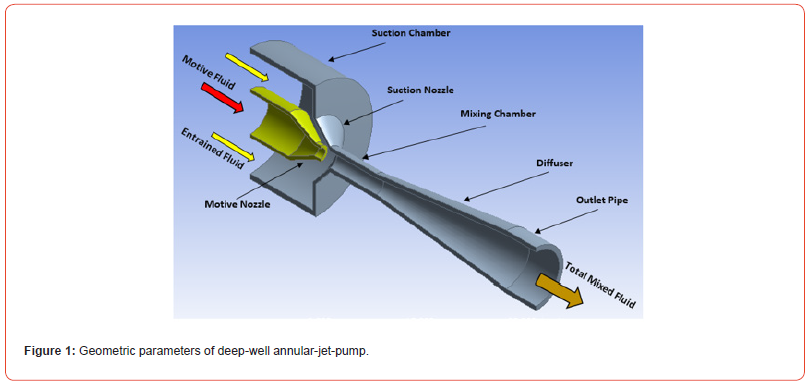
The motive nozzle’s exit length is critical for effective jet pump performance. Petroleum firms have encouraged manufacturers and researchers to focus on increasing jet pump efficiency in order to reduce the amount of motive power consumed. Over the last few years, an increasing number of energy-saving technologies have been developed [5] and [6,7] conducted a jet pump experiment investigation. They concluded that a ratio of approximately 1.2 was the ideal nozzle-to-throat spacing to nozzle diameter. [8] performed a numerical prediction to determine the ideal mixing throat length for the central jet pump’s drive nozzle position. Using threedimensional numerical analysis, they looked into how altering the driving nozzle position affected the pressure distribution and flow pattern through the pump. They concluded that the ratio of nozzle to mixing throat diameters (dn/dt = 0.6) and mixing length to mixing diameter (Lt/dt = 3.5) yield the highest efficiency. [9] provided experimental findings regarding the operation of a waterjet pump with two distinct suction designs and configurations. His findings demonstrated that, at nozzle spacing of (Z=1.25), the ideal motive fluid pressure value is approximately 1.5 bar, and the ideal nozzle-to-throat spacing to nozzle diameter ratio is approximately 1.25. [10] conducted an experimental investigation to look into how varied flow rates and motive pressures affected the performance of the jet pump in relation to the area ratio, mixing chamber length, diffuser angle, and nozzle to throat spacing. Their findings showed that around one is the ideal nozzle spacing (Z) value for pumping water [11] conducted a numerical simulation investigation on an axial jet pump utilizing four different turbulence models: the transition SST model, the RSM model, the SST k-ω model, and the realizable k-ε model. They contrasted every model result with the findings of the experiment. The comparison showed that the transition SST model outperformed the other models in terms of accuracy. They also found that, for model studies of axial jet pumps, CFD seems to be the most suitable tool [12] studied the impact of motive nozzle spacing on pump performance both numerically and experimentally. They concluded that the pumping liquid is susceptible to cavitation when the nozzle to throat separation is reduced to zero, and that the greatest efficiency of 25.6% occurs at Z = 0.5. [13] enumerated the crucial factors to be taken into account when creating a jet pump [14] carried out experimental investigations to find the ideal water jet pump design specifications. They revealed that as the area ratio increased the ideal value of Z also increased slightly [15] investigated venture ejector performance, specifically examining how geometric parameters affected ejector performance. According to their findings, the ideal ratio of (Lt/dn), or mixing throat length to nozzle diameter, is between 2 and 3.5. [16] experimentally examined the jet pump’s performance under various operating and design conditions. They conducted experiments with varying nozzle relative position (Z) to obtain the optimum value.
They discovered that 1.25 is the ideal nozzle relative position for water pumping. When pumping a water-sand mixture, the value of one is ideal [17] conducted an experimental and numerical analysis to find the ideal value for the axial water-jet pump’s nozzle relative location. They came to the conclusion that one is the ideal value for the nozzle relative location. As a result, the current study concentrated on how motive nozzle’s exit length affected the wateroil jet pump’s ability to extract crude oil from petroleum sites. Additionally defining the ideal motive nozzle’s exit length. The current study uses both computational and experimental methods to achieve this purpose. Using field data, experimental work is conducted in one of Egypt’s offshore oil fields. ANSYS software is used for computational work, and validation is done not just using field data but also with earlier computational and experimental results.
Research Methodology
Given that jet pumps are the most widely used artificial lift technology in Egypt and the rest of the world, a detailed analysis of the impact of motive nozzle’s exit length on jet pump performance is necessary to comprehend the relationship between motive nozzle’s exit length and jet pump performance. This goal primarily focuses on choosing the ideal motive nozzle’s exit length to maximize the production of deep-well jet pumps. The impact of motive nozzle exit length on the water-oil jet pump’s efficiency was examined in a recent study using the CFD commercial package ANSYS® FLUENT, Release 17.0. Furthermore, the impact of both motive nozzle’s exit length and its absence on motive energy loss leading to low efficiency will be examined.
The Numerical Model
An academic edition of the ANSYS Fluent R 17.0 CFD code was used for the computations, which included a finite volume discretization. Through the use of the pump, a three-dimensional steady-state water flow is used in the numerical simulation. The aim of the jet pump benchmark testing was to examine the effect of motive nozzle’s exit length on the performance of axial water-oil jet pumps. Additionally, experiment with this different geometrical variable to see how the pump’s flow responds. Previous work [13] recommended the SST k-ω turbulence model for the present study. The flow of an axial water-oil jet pump is a mixture of flows for which complex physics is involved.
The computational domain was limited to half of the axial jet pump instead of the full pump due to the rotational symmetry. The boundary condition of rotational symmetry was applied to the fluid zone. ANSYS Meshing was used to create hybrid meshes. It took about 316698 cells for the pump to provide mesh-independent solutions. In the area along the wall boundaries, inflated mesh was used to improve the boundary layer simulation’s accuracy. During the inflated meshing process, sets of two to eight prismatic inflation cell layers were first generated individually in the near-wall region. A first layer height of 45×10^ (-3) m and a growth rate of 1.2 were applied to each layer. To enhance the resolution of the turbulent flow field, a 3D double-precision pressure-based solver type was employed. In this numerical simulation investigation, the total pressures of the motive flow are used as the pressure inlet boundary condition. To determine the turbulence boundary conditions for each run, the turbulence strength and intermittency were used. According to the SST k-ω model calculations, the jet pump’s inlets and outlet have turbulence intensities and intermittencies set to 1 and 5%, respectively Figure 2 shows the generated structured mesh used in the present study.

PetroGulf Misr Company’s Field Information
Roughly 80 kilometers northwest of Hurghada City, the concession lands are situated in a shallow sea archipelago in the southwest inlet of the Gulf of Suez. The company is considered one of the Egyptian offshore oil fields. Concession areas include Geisum Field and Tawila West Field. EGPC and Conoco formed the corporation as a joint venture, which was first called Geisum. In South Field, the company had effectively drilled four wells between 1985 and 1987, when the partnership was in place. The Geisum Oil Company was renamed PetroGulf Misr Company in 2008 with the establishment of a joint partnership firm by Ganope, Pico Gos Petroleum firm limited, and Kufpec (Egypt) limited.
The Current Study’s Description and Input Parameters for Well “GA-1A”
Drilling well “GA-1A” was done in order to produce oil from the company’s south field, which is situated in Egypt close to the Gulf of Suez’s southwest entrance. That was thirty-seven years ago. The final depth of the drilling was 4715 feet. The well produced 22.1 API oil with a GOR of 180 scf/stb and 97% water cut through a 4.50-inch (2.99-inch ID) tubing placed in a 7-inch casing with a pump system. The specific gravity of water is 1.21 and that of gas is 0.809. The wellhead is 123°F, while the reservoir is 140°F. The reverse flow technique configuration is shown in Figure 3. Further information is available from [18], [19] and [20] Figure 4&5.
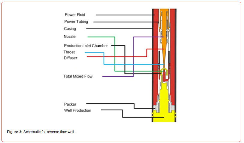
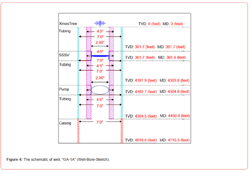

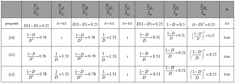
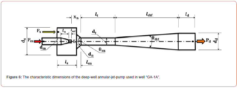
The deep-well jet pump’s smooth inner surface (K_s=20 × 10^ (-6) mm) is the result of its design and fabrication process using tungsten carbide. The typical dimensions of the deep-well annularjet pump used to produce oil from the “GA-1A” are displayed in Figure 6. The actual dimensions of the used pump are mentioned in Table 1.
Table 1:The dimensions of jet pump used in well «GA-1A».
Conclusions
This study examined how the motive nozzle’s exit length
affected the efficiency of the axial water-oil jet pump, which in turn
affected oil production. Using experimental field data from real oil
well and numerical techniques, the optimization study produced
the following findings:
a) The motive nozzle’s exit length is considered to be an
essential factor in minimizing motive energy loss, which leads
to low efficiency, and its optimization is mandatory.
b) It has been discovered that the motive nozzle’s exit length
has a significant impact on productivity. Additionally, it is
important to optimize the motive nozzle’s exit length because
it can increase pump production by 23.69%.
c) The optimal motive nozzle’s exit length is found to be 10
mm.
d) The physics of flow within axial water-oil jet pumps can be
studied and the optimization can be easily carried out by using
the CFD, a 3D technique to predict one or more geometrical
parameters on the pump efficiency. This will help to save time
and money spent in the actual oil field.
Acknowledgement
None.
Conflict of Interest
No conflict of interest.
References
- API E&P Dept. (1994) API Gas Lift Manual. Book 6 of the Vocational Training Series, pp. 1-67.
- Karassik IJ, Messina JP, Cooper P (2008) Heald CC. Pump Handbook. 4th, McGraw-Hill, Professional Access Engineering, New York, USA.
- Shimizu Y, Nakamura S. Kuzuhara S, Kurata S (1987) Studies of the configuration and performance of annular type jet pump. J. Fluids Eng 109: 205-212.
- Xiao L, Long X, Yang X (2014) Numerical investigation on the influence of nozzle lip thickness on the flow field and performance of an annular jet pump. J. Harbin Inst. Technol 31 (3): 59-67.
- Li X, Jiang Z, Zhu Z, Si Q, Li Y (2018) Entropy generation analysis for the cavitating head-drop characteristic of a centrifugal pump. Proceedings of the Institution of Mechanical Engineers, Part C: Journal of Mechanical Engineering Science 232(24): 4637-4646.
- Fangwei X, Rui X, Gang S, Cuntang W (2017) Flow characteristics of accelerating pump in hydraulic-type wind power generation system under different wind speeds. The International Journal of Advanced Manufacturing Technology 92: 189-196.
- El-Sibaie AM, El-Haggar SM (1987) Performance characteristics of a slurry jet pump aided by a centrifugal pump. Ain Shams University, Egypt, Mech. Eng 2(2): 149-160.
- Chamlong P, Aoki K (2002) Numerical prediction on the optimum mixing throat length for drive nozzle position of the central jet pump. Proceedings of Tenth international symposium on flow visualization, Kyoto, Japan.
- Hammoud AH (2006) Effect of Design and Operational Parameters on Jet Pump Performance. Proceedings of the 4th WSEAS International Conference on Fluid Mechanics and Aerodynamics, Elounda, Greece pp. 245-252.
- El-Sawaf IA, Halawa MA, Younes MA, Teaima IR (2011)23 pp. f the Different Parameters That Influence on the Performance of Water Jet Pump. Fifteenth International Water Technology Conference, IWTC 15, Alexandria, Egypt.
- Aldas K, Yapici R (2014) Investigation of Effects of Scale and Surface Roughness on Efficiency of Water Jet Pumps Using CFD. Eng. Appl. Comput. Fluid Mech 8: 14-25.
- Teaima IR, Meakhail TA (2013) A Study of the Effect of Nozzle Spacing and Driving Pressure on the Water Jet Pump Performance. International Journal of Engineering Science and Innovative Technology (IJESIT) 2(5).
- Sheha AAA (2017) Study of Jet Pump Performance, M. Sc. Thesis, Faculty of Engineering, Menoufia University, Egypt.
- Hansen AG, Kinnavy R (1965) The Design of Water Jet Pumps Part-I: Experimental Determination of Optimum Design Parameters. ASME paper 65-WA/FE-31, pp. 1-8.
- Iran E, Rodrigo E (2004) Performance of Low-Cost Ejectors. Journal of Irrigation and Drainage Engineering, ASCE trans., pp. 122-128.
- Hammoud AH, Abdel Naby AA (2006) Slurry Jet Pump Performance: Under Different Design and Operational Parameters. Proceedings of the 4th WSEAS International Conference on Fluid Mechanics and Aerodynamics, Elounda, Greece, pp. 237-244.
- Sheha AAA, Nasr M, Hosien MA, Wahba M (2018) Computational and Experimental Study on the Water-Jet Pump Performance, Journal of Applied Fluid Mechanices 11(4): 1013-1020.
- Sheha AAA, Ibrahim KA, Abdalla HA, El-Behery SM, Sakr IM (2023) Improvement of the axial-jet-pump performance using modified mixing chamber configuration and inlet swirling flow. Scientia Iranica.
- Sheha AAA, Ibrahim KA, Abdalla HA, Sakr IM, El-Behery SM (2023) Optimal performance of water-oil axial jet pump in an egyptian offshore oil field. Petroleum Research.
- Sheha AAA, Ibrahim KA, Abdalla HA, El-Behery SM, Sakr IM (2023) The Impact of Motive Nozzle Spacing and Surface Roughness on The Performance of Axial Water-Oil Jet Pumps in an Egyptian Offshore Oil Field: An Experimental and Computational Investigation. Online Journal of Robotics & Automation Technology 2(3).
-
AAA Sheha*, KA Ibrahim, H A Abdalla, I M Sakr and Samy M El Behery. Computational and Experimental Study on the Effect of Motive Nozzle’s Exit Length of Axial Water-Oil Jet Pumps in an Egyptian Offshore Oil Field. On Journ of Robotics & Autom. 2(5): 2024. OJRAT.MS.ID.000549.
Axial Water-Oil Jet Pump; Motive Nozzle's Exit Length; Performance; Experimental Field Data; Computational
-

This work is licensed under a Creative Commons Attribution-NonCommercial 4.0 International License.


