 Research Article
CFD Analysis of CD Nozzle with Sharp Throat and CD Nozzle with Curved Throat
Shamsher Ali Ansari and Pramod Chaudhary*
Department of Aeronautical Engineering, Vel Tech Rangarajan Dr. Sagunthala R&D Institute of Science of Technology, Chennai, Tamil Nadu, India
Pramod Chaudhary, Department of Aeronautical Engineering, Vel Tech Rangarajan Dr. Sagunthala R&D Institute of Science of Technology, Chennai, Tamil Nadu, India
Received Date:March 14, 2024; Published Date:March 28, 2024
Abstract
A nozzle is one of the major components of a jet engine whose prime objective is to produce thrust to propel the aircraft or rocket. It is a specially engineered tube through which extremely hot gases flow. It is designed in such a unique way that allows fluid (usually a gas or a mixture of gases) to accelerate to high speeds, mostly supersonic or hypersonic, by controlling its shape and dimensions. In detail, we can say that the nozzle is used as a pathway for the exhaust gases to mix with the atmospheric air, to produce thrust and to establish a continuous mass flow rate through the engine. It converts thermal and pressure energy into kinetic energy which in turn produces the thrust required by the aircraft. The nozzle (especially the CD nozzle) shows its strong use in fields like rocket propulsion, jet engines to propel aircraft, aerospace research, electricity production, supersonic flow measurement, wind tunnels, gas expansion, cooling, etc.
Computational Fluid Dynamics (CFD) is a branch of fluid mechanics that makes use of numerical methods, formulas, and algorithms to solve and analyze fluid flow. A convergent-divergent nozzle, also called a de-Laval nozzle is one of the types of nozzles that is used when supersonic flow velocity is needed. CFD has allowed us to study and predict the behavior of fluids (either liquids or gases) in various physical conditions without the actual need for conducting physical experiments. It allows us to perform numerical simulation, offers flexibility in geometry design, and gives us a platform to carry out various operations of turbulence model, heat transfer, multi-phase flow, boundary condition, etc. The use is not just limited to aerospace engineering and automobile engineering, rather it is widely used in biomedical engineering, electronics, chemical processes, marine engineering, nuclear engineering, etc.
Keywords:CFD; Mach number; Subsonic; CD Nozzle
Introduction
Jet engines have revolutionized the world of technology, and the aerospace industry and space mission has seen exponential growth. It has contributed a lot to the propulsion system. A jet engine is a kind of propulsion device that produces thrust by expelling exhaust gases at a very high speed [1]. It works on Newton’s third law of motion which says that for every action, there is an equal but opposite reaction. The major components used in a jet engine are the inlet, compressor, combustor, turbine, and nozzle at the exit. All these parts function together to produce thrust. An inlet allows air to enter where the air slows down and the pressure increases. The compressor comes after the inlet which consists of rotating blades. These blades are designed in such a way that compresses the air and increases the pressure of the incoming air. Different configurations of the compressor blades are used to compress the air. The highly compressed air is mixed with fuel sprayed through the injector and combustions occur in the combustion chamber producing very high temperature and high pressure. These gases rotate the turbine which extracts some work from it. The gases pass through the nozzle which is a non-stationary part. The nozzle accelerates the gases to a very high speed which in turn produces thrust.
A nozzle is a simple device, a specially shaped tube through which hot gases flow. The last component used in a jet engine is the nozzle which is a key part in producing thrust to propel the aircraft and rocket. Various types of nozzles are available and are used based on our necessities. Turbofan engines use different kinds of nozzles, turbojets use different ones and rockets use different kinds of nozzles based on the convenience and thrust required [2]. Convergent nozzle, divergent nozzle, and convergent divergent nozzle (which is a combination of both the nozzles) are in practice. Nozzles are used in the aerospace industry. Similarly, they are used in power generation, especially electricity. They are used in space exploration, the military, producing compressed air in industries, etc.
The nozzle converts the internal energy of the fluid into thrust which, in turn, propels the aircraft forward. The energy possessed in the form of pressure and temperature is thus converted into thrust. It makes the fluid move at subsonic, sonic, and supersonic speeds based on the design and the Mach number of the working fluid. The inlet portion is attached to the turbine while the other end is open to the atmosphere. The pressure at the exit is called exit pressure or ambient pressure or back pressure or receiver pressure.
Since the ambient pressure is low in comparison to the pressure at the inlet of the nozzle, this causes the flow of the fluid as fluid flows from higher pressure to lower. The greater the difference in the pressure of the nozzle and ambient pressure, the faster the fluid flows across it. And the faster the flow, the higher the thrust. Following are the different types of nozzles and relations of the flow with an area of the duct.
Convergent nozzle
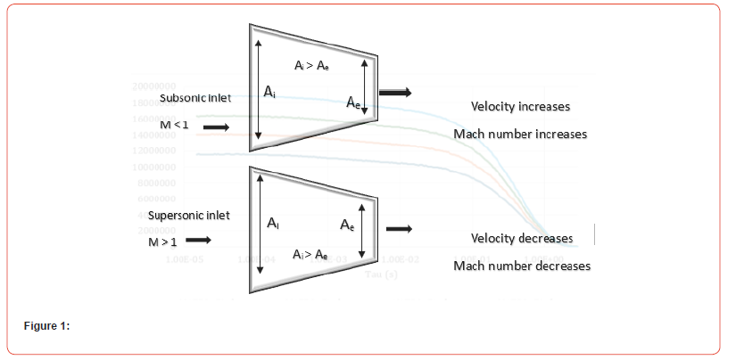
It is a nozzle in which the area at the inlet is greater than the area at the exit (Ai > Ae). It is normally used to accelerate the flow and thus increase the kinetic energy possessed by the fluid. However, it acts differently under different Mach numbers. For a subsonic flow, it acts as a nozzle by increasing the kinetic energy while things get reversed for a supersonic flow Figure 1.
Divergent nozzle
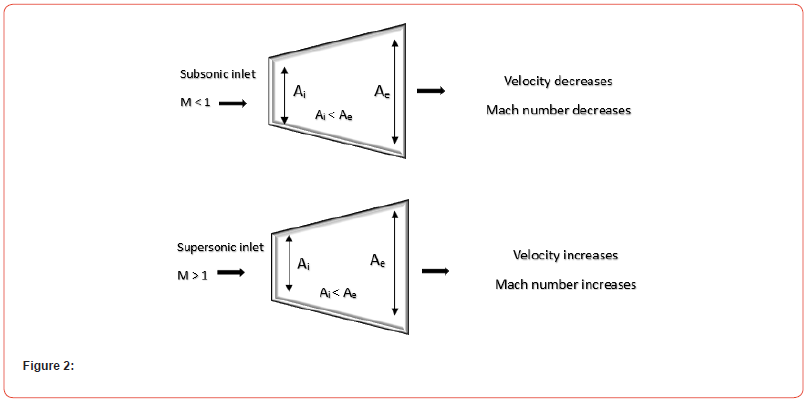
It is a nozzle in which the area at the inlet is smaller than the
area at the exit (Ai>Ae). It is normally used to decelerate the flow
and thus increase the kinetic energy possessed by the fluid. Diverging
design allows for the expansion of exhaust gases. Based on the
Mach number of gases at the inlet of the divergent nozzle, the properties
vary Figure 2.
M = Mach number
Ai = Inlet area
Ae = Outlet area
The condition of outlet (exit), whether velocity increases or decreases is determined by the following relation.
Intelligent control and modelling frontier to construct a sewing
stitches bank that will be able to charge all types of sewing machine.
a) Machine learning, adaptation and imitation of a sewing
machine that is capable of supplying 90 stitches current.
b) Innovative computations of a sewing machine with short
circuit protection.
c) Neural networks, neural computation sewing stitches
bank that as over-charging protection.
d) Micromachines control the frontier of a sewing machine
so that the sewing stitches is rechargeable.
e) The Sensor fusion and machine perception frontier in
sewing stitches industrial robotics for intelligent manufacturing.
Weaving Machine Bank [1]:
Sensor fusion and machine perception to construct a weaving
machine bank that will be able to charge all types of weaving
machine.
a) Multi-sensor fusion and perception control of weaving
machine bank that is capable of supplying many kinds of woven
fabric structures.
b) Machine learning and intelligence of a weaving machine
bank with short circuit protection.
c) Novel and emerging applications of weaving machine
bank that as over-charging protection.
d) Automated mining frontier weaving machine that the
weaving machine is rechargeable.
e) Digital image processing in weaving machine bank
industrial robotics for intelligent manufacturing
f) Adjustments in the inclinations of the rapier tapes for
passing wefts to achieve an increase in speed and productivity
rates in the specified time automatically.
g) Nuovo Pignon/SMIT machine repair, improvement
and machinery maintenance, repairs, maintenance and
improvements of weaving looms and automation textiles
machinery and increasing productivity and speed of the Sensor
fusion and machine perception frontier in industrial Robotics
for intelligent manufacturing in weaving machine model 1998
by change the inclination angle of the rapier bar to increase
speed and productivity to compete with modern models.
Methodology
Methodology is the study of research methods. However, the term can also refer to the methods themselves or to the philosophical discussion of associated background assumptions of automation and technical education for the digital future. A method is a structured procedure for bringing about a certain goal of technology banks in textiles industries, like acquiring knowledge or verifying knowledge IT system integration for compact of old machines in textile industries. This normally involves various steps, like choosing samples of Egyptian Nefertiti sewing machine and weaving “NuovoPignon/SMIT” model 1998, collecting data from this sample, and interpreting the data [18,19]. The study of methods concerns a detailed description and analysis of these processes. It includes evaluative aspects by comparing different methods.
Impact of 5G the manufacturing industry on machines in textile industries
a. Cloud control of machines.
b. Augmented reality.
c. Perceptive AI eyes on the factory floor.
d. High-speed decision-making.
e. Shopfloor IoTs.
Results and Discussions
The technology banks use a diverter less supersonic inlet, while
some producers use carbon-fiber composite in manufacturing.
The automation-digital used a sample duct automation intake to
prevent waves from reflecting off the engine compressor blades,
an important aspect of fifth-generation automation textiles and
clothing machines to reduce frontal vibrations and noise [20,21].
These are a few of the preferred methods employed in some
fifth-generation automation textiles and clothing machines, to
reduce vibrations. In addition to the introductory sections on the
mechatronics concept and design methodology and the impact
of advance in technology the digital future on the mechatronics
concept [22,23]; at the present time, to transform the lives of people
not heavily invested in textile industries, for instance.
a) To update purchases and “business class” plans.
b) Selling 5G-enabled experiences.
c) Using partnerships to deliver 5G-enabled experiences.
The importance of the mechatronic design in the automation textiles industries is highlighted, as in figure1 together with many examples of artificial intelligence applications in the automation textiles industries include:

M = Mach number
The speed of an object is normally taken in terms of Mach number for our convenience. Mach number, also called Mach, is a non-dimensional quantity that is defined as the ratio of the velocity of an object to the speed of sound in that medium. The speed of an object at different Mach numbers has been categorized as follows Table 1.
Table 1:

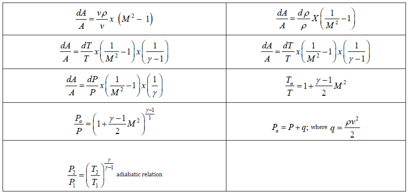
From the above-mentioned relation between change in area and velocity dA/A=dv/v X[M2-1], we can calculate the velocity change with the change in area. Consider a convergent nozzle, the area constantly decreases which means change in area is negative. When the flow is subsonic means that gives the value of (M2 −1) negative and less than 1. When we divide the change in area (which is negative) by (M2 −1) which is negative itself and is less than 1, we get the value of change in velocity as positive and greater than 1. This signifies that the change in velocity across the convergent duct increases subsonic flow. However, the case reverses for a supersonic flow. In the same way, the above relation can be used for a divergent duct. In a divergent nozzle, when the inlet is in subsonic condition, the velocity decreases and thus the kinetic energy decreases. And for a supersonic inlet, the velocity increases in the divergent nozzle [3].
Convergent-Divergent (CD) nozzle
Convergent-Divergent nozzle is also called de Laval nozzle, which is the combination of both the convergent and divergent nozzle. It is a special type of nozzle in which divergent and convergent nozzles are joined to form a CD nozzle Figure 3&4

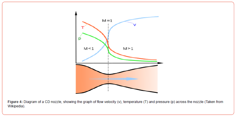
From the diagram above, it can be seen that velocity (given in terms of Mach number) increases from subsonic in the convergent section to sonic at the throat becoming supersonic towards the divergent section. However, at the inlet of the nozzle, the static pressure and temperature is maximum which decreases as the fluid moves from the inlet towards the throat and the exit. We consider that the flow in the nozzle is isentropic, thus total pressure and total temperature remain constant throughout. However, due to irreversibility caused by friction, the isentropic condition is unachievable. As a result, the total exit pressure is lesser than the total pressure at the inlet. There are no moving parts, and no work is imparted nor any work is done by or on the fluid during the entire process and thus there is no change in total temperature. However, leakage, heat conduction, etc. through the parts will cause a decrease in the total temperature. Similarly, this process is considered as an adiabatic process as there is no exchange nor addition of energy during the flow and the corresponding expansion is considered as an adiabatic expansion.
Total heat exchange i.e., dQ = 0 (Due to adiabatic process)
Total work done i.e., dW = 0 (No work is done)
Total entropy changes i.e., dS = 0 (Isentropic process for ideal
nozzle)
This analysis of the pressure, velocity, temperature, and density across the CD nozzle is carried out by simulation using CFD [4]. Computational Fluid Dynamics (CFD) is a branch of fluid mechanics that makes use of numerical methods, formulas, and algorithms to solve and analyze fluid flow. CFD visualizes the fluid flow, and it depicts the way the object gets affected by the digital simulation. It uses complex formulas and advanced algorithms to solve the problem with the help of a computer. It makes use of different equations such as continuity equation, momentum equation, energy equation, partial differential equation, etc. to show the actual flow that might occur on an object. It is used to show flow characteristics in aerodynamics, to carry analysis in propulsion, in control systems, in aerospace industries, in mechanical industries, and has tons of other applications. The accuracy of the data with the actual experiment is what makes CFD a preferable tool for engineers to conduct their research and analysis.
Basic Relations
Table 2:
• Steady state energy equation Since the process is adiabatic i.e., dQ = 0 and there is no transfer of
work i.e., dW = 0, the equation will be:
  per unit
mass.

Standard Dimensions of Nozzles
• Total length of the nozzle = 1 m
• Inlet diameter = 0.66756 m
• Outlet diameter = 0.66756 m
• Throat diameter = 0.35682 m
• Distance between throat and exit = 0.5 m
• Distance between inlet and throat 0.5 m
Simulation
The simulation was performed using the ANSYS Fluent 2020 R1 version. The process was completed in the following steps and the result was obtained.
Geometry design
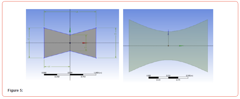
Two nozzles of different dimensions were designed in Ansys Design Modeler. The nozzle with a sharp throat has a total length of 1 m. The inlet and outlet height were both 0.667558118m along with a throat diameter of 0.356824823 m. The nozzle with a curved throat has a similar dimension but was quadratic in nature i.e., y = 0.1 + x2; -0.5 < x < 0.5. y is the distance on the y-axis and x is the value on the x-axis whose domain is from -0.5 to 0.5. A total of 201 values were calculated from the above equation and then imported into the Ansys Design modeler. It was found that the inlet and outlet height were both 0.667558118 m along with the throat diameter being 0.356824823 m. The length of the nozzle is considered 1 m Figure 5.
Meshing
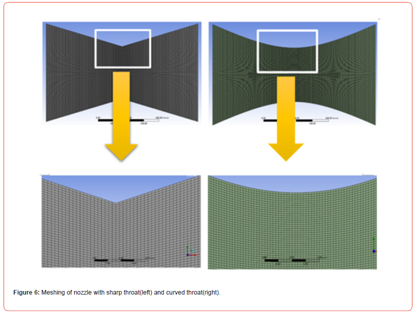
Meshing facilitates accurate simulation of flow. Meshing divides the geometry into discrete cells or domains called mesh, where the governing equation can be assigned to each cell. The quality of the mesh determines the accuracy of the result [5]. The stability of the simulation depends on smooth and accurate meshing. We have used the automatic method on the whole body where we have selected the quadrilateral dominant method. We have used face sizing on the face, with an element size of 0.05mm similarly, face meshing is used which gives quadrilateral cells. The skew was taken below 0.15 and smoothing was of high quality. The meshing obtained was regular and had quadrilateral cells of no distortion. Below is the meshing of these two nozzles Figure 6.
Solution
• The energy equation was activated, and the k-epsilon(standard)
viscous model was selected with a standard wall function.
• Ideal gas was selected. Viscosity – Sutherland law with three
coefficient method with reference viscosity 1.716e-05 kg/m-s
was used.
• The materials used were air and ideal gas was considered for
the entire process for both cases.
• Pressure inlet, with a total pressure of 3 bar was taken considering
300 K total temperature. This pressure was taken into
consideration for both the nozzles. Outlet pressure was kept
at 0 bars while the operating condition was taken as default of
101325 Pascal.
• The wall is considered stationary, and we have taken no slip
condition on the wall.
• Second-order upwind was considered for the flow, turbulent
kinetic energy, and turbulent dissipation rate.
• The flow was computed from the inlet.
• Courant number = 5
• 2000 number of iterations were taken, and the solution was
converged at around 1600 iterations (for the first nozzle) and
Iterations while the solution was converged at around 1200
iterations (for the second nozzle).
• Pre-processing
• Pre-processing of the nozzle was done in ANSYS FLUENT. 2-D
and double-precision settings were used. Two solver processes
were selected for the solution.
Pre-processing
Pre-processing of the nozzle was done in ANSYS FLUENT. 2-D and double precision settings were used. Two solver processes were selected for the solution.
Residual monitor
Table 3:

Results and discussion
The result converged at around 1600 iterations for the nozzle with a sharp throat and 1200 iterations for the nozzle with a curved throat. After the simulation, we analyzed our results. Our main focus is on the property variation of pressure, velocity, temperature, density, etc. across the nozzle. We have concluded our result as follows.
Pressure
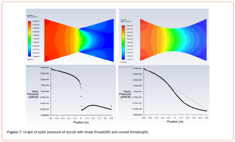
Pressure is defined as the force acting per unit area. We have been using pressure in different forms such as total pressure, static pressure, dynamic pressure, hydrostatic pressure, atmospheric pressure, stagnation pressure, gauge pressure, vacuum pressure, etc. Here, we have considered static pressure, dynamic pressure, and pressure coefficient as our observations. We are taking static pressure, which is the pressure of a fluid at a specific point in a fluid flow field when the fluid is not moving. It represents the pressure that a fluid would exert on a surface at that point if we were to make that fluid rest [6]. It is an important component of total pressure. In both nozzles, the static pressure at the inlet is almost the same. While we move towards the throat in the first nozzle, static pressure decreases slowly at first and then it decreases exponentially as shown in the graph. After crossing the throat, pressure increases at first and then decreases gradually. In the second nozzle, static pressure shows constant decrement as if the graph is almost linear from inlet to throat. We can see that in the second nozzle, the pressure drop is gradual [7]. As we move far towards the exit, we can see that the decrease in pressure is very slow. The decrease in the static pressure in the second case is gradual (almost linear). In the nozzle with a sharp throat (first nozzle), the pressure drop is very sudden and shows an exponential drop while in the nozzle with a curved throat (second nozzle), the pressure drop is gradual and after the throat, the curvature is the graph is more than curvature before the throat as shown by the arrow line Figure 7.
The following contours belong to dynamic pressure. Dynamic pressure is a crucial component of total pressure. It is a term used in the fluid dynamic which is the pressure exerted by fluid that is in motion or fluid that flows. Dynamic pressure is directly proportional to the velocity of the fluid. If the velocity increases, dynamic pressure increases as well, and vice versa. In the first nozzle, dynamic pressure increases rapidly and becomes highest at the throat. Afterward, it falls drastically after throat and then shows almost constant increment and decrement as shown in the graph. Similarly, in the second nozzle, dynamic pressure increases linearly and becomes maximum at the throat. Then, it decreases linearly after throat as shown in the diagram Figure 8&9.
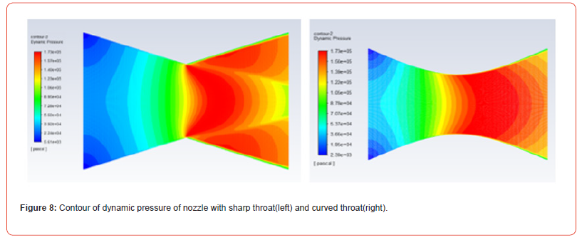
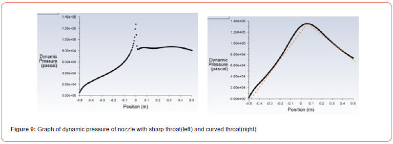
The following contours belong to dynamic pressure. Dynamic pressure is a crucial component of total pressure. It is a term used in the fluid dynamic which is the pressure exerted by fluid that is in motion or fluid that flows. Dynamic pressure is directly proportional to the velocity of the fluid. If the velocity increases, dynamic pressure increases as well, and vice versa. In the first nozzle, dynamic pressure increases rapidly and becomes highest at the throat. Afterward, it falls drastically after throat and then shows almost constant increment and decrement as shown in the graph. Similarly, in the second nozzle, dynamic pressure increases linearly and becomes maximum at the throat. Then, it decreases linearly after throat as shown in the diagram.
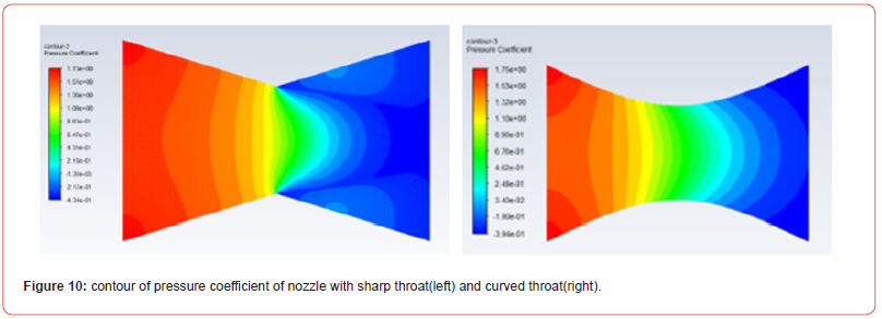
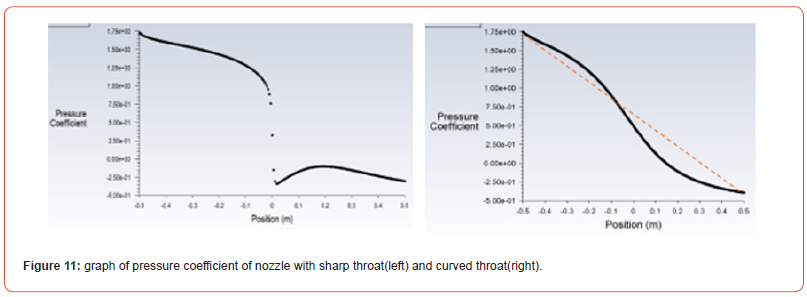
The coefficient of pressure also known as pressure coefficient is a dimensionless quantity which is the ratio of the difference of the static pressure at the point in the freestream and free stream static pressure to the dynamic pressure of the free stream. It is given by

Towards the inlet section, the static pressure is maximum, and this the coefficient of pressure is highest. Similarly, as the static pressure decreases while moving away from the inlet, so does the coefficient. In both the nozzles, the pressure coefficient is the same at the inlet and similar at the outlet. However, in the first nozzle, the pressure coefficient follows the pattern same as in the static pressure [8]. While we move towards the throat in the first nozzle, the pressure coefficient decreases slowly at first and then it decreases exponentially as shown in the graph. While in the second nozzle, Cp shows constant decrement as if the graph is almost linear from inlet to throat. After crossing the throat, Cp increases at first and then decreases gradually. In the second nozzle, the drop in pressure coefficient is gradual and after the throat there is more curvature in the Cp decrement. As we move far towards the exit, we can see that the decrease in pressure is very slow
Temperature
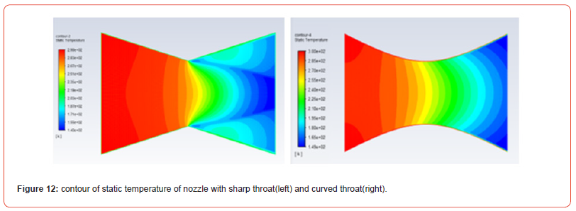
The property of static temperature is similar to that of static pressure. Static temperature is highest at the inlet which is about 300K. As we move towards the throat in the first nozzle, it decreases. Further back to the throat, it decreases sharply as velocity increases rapidly. It should be noted that total temperature remains constant even if it encounters shock waves for an ideal case. The total temperature remains constant throughout the process unless energy is supplied to or lost from the system. In the second nozzle, the temperature shows a uniform drop. Towards the walls of the first nozzle, the temperature is more than the middle part of the diverging nozzle while there are no such scenes in the second nozzle. The graph shows a similar pattern as static pressure Figure 12.
Velocity and Mach Number
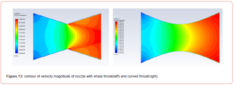
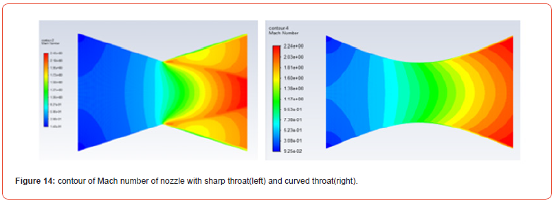
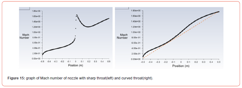
The prime use of this nozzle is to accelerate the flow at a very high speed and get a tremendous amount of thrust. The front portion of the CD nozzle is a convergent nozzle that accelerates the flow when the fluid is at subsonic condition based on: dA/A=dv/v X[M2-1] relation. The flow slowly accelerates and becomes sonic at the throat. The flow is maximum at the throat. Now, the nozzle is divergent, and the flow accelerates further and becomes supersonic. Velocity is represented in terms of Mach number also called Mach is a non-dimensional quantity which is defined as the ratio of the velocity of an object to the speed of sound in that medium. Looking at the Mach number, in the first nozzle, the Mach number increases gradually at first and then rises exponentially as fluid approaches the throat region. After the throat fluid flow further decreases quickly and afterward the flow speeds up showing even progression. In the second nozzle, flow velocity shows a linear correlation which increases gradually Figure 13,14&15.
Density
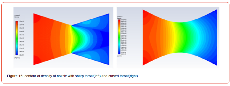
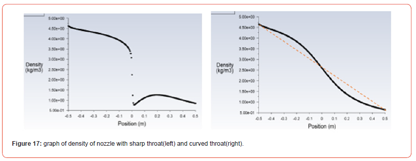
The density is defined as the ratio of mass occupied per unit volume. The density of solid is the highest and that of gas is the lowest among matters. Based on the given relation: 2 dA/A=dρ/ρ X(1/M2-1)with the increase in Mach number, density decreases. Similarly, from the gas equation P = ρRsT , Where s R is the specific gas constant given as the ratio of universal gas constant to the molecular mass, ρ is the density of the gas, T is the temperature in kelvin and P is the pressure. So, in an ideal case, we can rely on the relation that with the increase in pressure, density increases and vice versa. At the inlet, density is maximum in both cases. In the first nozzle, density gradually decreases at first and then decreases tremendously as we approach toward throat. Upon further moving towards the exit, the density shows a slight increment and then decreases gradually towards the exit [9]. While in the second nozzle, density decreases similar almost linearly. After the throat, there is more curvature in the density graph in the second nozzlessss Figure 16&17.
Conclusion
Based on the above analysis, we can conclude the following:
• static pressure decreases as we move away from the inlet.
While the decrease in pressure in the first nozzle is non-uniform
and shows exponential decrement, the second nozzle
shows almost linear variation of static pressure across the
length of the nozzle.
• dynamic pressure increases moving away from the inlet and is
maximum at the throat. In the first nozzle dynamic pressure
shows an exponential increase towards the throat region and
decreases suddenly after the throat. In the second nozzle, however,
dynamic pressure increases almost linearly becoming
maximum at the throat, and then decreases in a steady progression.
• temperature decreases in the direction from inlet to exit. In the
first nozzle, temperature shows a sudden drop up to the throat
region and then decreases linearly. However, in the second
nozzle, there is an almost linear variation of the temperature.
• velocity increases in both the convergent and divergent sections.
Velocity is subsonic in the convergent section and becomes
supersonic in the divergent section. In the first nozzle,
flow speed increases gradually at first and then rises exponentially
as fluid approaches the throat region. After the throat fluid
flow further decreases quickly and afterward the flow speed
increases showing even progression. In the second nozzle, flow
velocity shows a linear correlation which increases gradually.
• Density gradually decreases at first and then decreases suddenly
as we approach the throat. Upon further moving toward
the exit, the density shows a slight increment and then decreases
gradually towards the exit. While in the second nozzle,
density decreases similar to static pressure in the second
nozzle. After the throat, there is more curvature in the density
graph.
In the nozzle with a sharp throat region, there is a sudden variation of the properties. The properties show exponential variation near the throat region. While in the nozzle with the curved throat, the variation in the properties is gradual and shows almost linear variation.
References
- Sher Afghan Khan, Omar Mohamed Ibrahim, Abdul Aabid (2021) CFD Analysis of Compressible Flows in a Convergent-Divergent Nozzle.
- Sher Afghan Khan, Abdul Aabid, Maughal Ahmed Ali Baig (2018) CFD Analysis of CD Nozzle and Effect of Nozzle Pressure Ratio on Pressure and Velocity for Suddenly Expanded Flows.
- BVV Naga Sudhakar, B Purna Chandra Sekhar, P Narendra Mohan, Md Touseef Ahmad (2016) Modeling, and simulation of Convergent-Divergent Nozzle Using Computational Fluid Dynamics.
- R Ramesh Kumar, Yuvarajan Devarajan (2018) CFD Simulation Analysis of Two-Dimensional Convergent-Divergent Nozzle.
- Rahul Rai, Danish Khan, Vikas Kumar Chauhan, Flow Analysis in a Convergent-Divergent Nozzle Using CFD.
- Gutti Rajeswara Rao, U.S. Ramakanth, A. Lakshman, Flow Analysis in a Convergent-Divergent Nozzle Using CFD.
- G Satyanarayana, Ch Varun, SS Naidu, CFD Analysis of Convergent-Divergent Nozzle.
- AA Khan, TR Shobhakar, Viscous Flow Analysis in a Convergent-Divergent Nozzle.
- Shamsher Ali Ansari (2023) Analysis of CD Nozzle by CFD Simulation.
-
Shamsher Ali Ansari and Pramod Chaudhary*. CFD Analysis of CD Nozzle with Sharp Throat and CD Nozzle with Curved Throat. On Journ of Robotics & Autom. 2(4): 2024. OJRAT.MS.ID.000542.
CFD; Mach number; Subsonic; CD Nozzle
-

This work is licensed under a Creative Commons Attribution-NonCommercial 4.0 International License.


