


 Research article
Review of the Exchange Anisotropy and the Methods of Investigation
Received Date: May 14, 2024 Published Date: May 28, 2024
Abstract
The present work deals with the exchange anisotropy. Such unidirectional anisotropy arises from the interaction at the interface of a
ferromagnetic (F) and an antiferromagnetic (AF) thin film. The interaction can be modeled as an internal magnetic field HE called the exchange
anisotropy field. The dependence of HE with (F) and (AF) thicknesses as well as with the temperature will be discussed. Different models describing
the interface state will be given; these include the aligned and the off-aligned exchange anisotropy. Some applications of this anisotropy will be
described. The methods for the investigation of this phenomenon will be discussed. Three set-ups will be highlighted.
(i) The hysteresis curve and the shift induced by the exchange anisotropy.
(ii) For the torque curve method, it will be shown how from some features of the torque curve, one may derive the exchange and the planar anisotropy
fields as well as the off-aligned angle .
(iii) For the Ferromagnetic Resonance (FMR) technique, the resonance relations are derived in different situations, the effects of HE and β on the
position of the FMR peaks are inferred. These specific FMR characteristics allow one to derive the parameters pertaining to the exchange anisotropy.
For these methods, different magnetic anisotropies in the (F) thin film are considered and the way to measure the exchange anisotropy field will be
highlighted.
Keywords: Exchange anisotropy; Magnetic anisotropy; Hysteresis curve; Torque curve; Ferromagnetic resonance.
Introduction
The system under study here consists of a ferromagnetic and an antiferromagnetic thin films, labeled as (F)/(AF). The interaction between the (F) and (AF) magnetic moments, at the interface, gives rise to a unidirectional anisotropy called exchange anisotropy. This effect was observed in 1956 in the Co/CoO bilayers by Meiklejohn and Bean [1]. Other systems have been found to exhibit such a phenomenon which is intensively studied [2-12]. Both theoretical and experimental works [13-20] were undertaken to get insight on the origins of the exchange anisotropy and to account for the different effects observed in the (F)/(AF) bilayers.
The exchange anisotropy is defined in Section 2. Also, in order to ensure that the magnetic moments of (F) and (AF), at the interface, are parallel and coupled, so that the interaction is strong enough to lead to the exchange anisotropy, some preparation conditions or some post-deposition treatments are required [21-25]. These conditions will be discussed in Section 2.
The interest in this system is motivated by fundamental research as well as for applied research. One of the applications of this exchange anisotropy in (AF)/(F) is in magnetic recording technology; it was proposed as a bias in magnetoresistive heads [26] (see Section 3). The exchange anisotropy is used in some spintronic devices [27-29] and in permanent magnet materials [29, 30]. The exchange anisotropy can be modelled as an internal magnetic field called the exchange anisotropy field, H E (Section 3.1). The HE field is found to strongly depend on the (F) thickness, tF, on the (AF) thickness tAF and on the temperature T; these variations [31,36] will be discussed in Section 3.2.
The state of the (F)/(AF) interface is important and has a strong effect on the magnitude of the exchange anisotropy. Theoretical models have been proposed to describe the spins at the interface and to understand the origin of this particular anisotropy. Different aspects of the interface will be described in Section 4; including the relationship between the structure and morphology of the interface and the exchange anisotropy behaviour [37-45]. Also, the aligned and the off-aligned cases are considered [46-51]. In the former, the (AF) and the (F) easy axes are parallel; while in the latter the easy axes of (AF) and (F) are not parallel but make an β angle between them; β is called the off-aligned angle.
As for the methods used to detect and measure the exchange anisotropy, the focus is on three methods in the present work: the hysteresis curve, the torque curve method and the Ferromagnetic Resonance (FMR). Other techniques have also been used to investigate the exchange anisotropy [52-57]; these methods will be cited in Section 5.
Note also that the exchange anisotropy has been found and investigated not only in (AF)/(F) bilayer but also in other systems [58-71]. Moreover, the phenomenon has been studied in a single (AF)/(F) bilayer and also when the (F)/(AF) is part of Magnetic Tunnel Junction (MTJ) structure [27,59,60, 63-65]. The latter is a stacking of (F)/(AF) bilayer and a trilayer consisting of two ferromagnetic layers separated a non-magnetic layer, i.e. (AF)/(F)/(nonmagn)/( F). The three experimental methods, discussed here, have also been used to study the exchange anisotropy field within the MTJ structure.
The hysteresis curve is the most used and the most popular method to detect and measure the exchange anisotropy [72-78]. The shifted M vs H loop is an indication of the existence of exchange anisotropy; the amount of shift being equal to HE. In Section 5.1, analytical expression will be derived for the saturation and the switching fields and hence for the magnetization curves. These fields will be found for the (F) layer characterized by an in-plane anisotropy, a cubic magnetocrystalline anisotropy and a perpendicular anisotropy. For the off-aligned case, analytical expressions of the critical fields are found for a particular situation (Section 5.1).
The torque curve method has been used to measure the anisotropy constants of a ferromagnetic thin film, in multilayer and in (F)/(AF) bilayer [79-83]. It will be shown that the torque method can be used to detect and measure the exchange anisotropy field HE and also the off-alignment angle β (for the off-aligned case). Analytical expressions giving HE and β are derived in Section 5.2.
The Ferromagnetic Resonance (FMR) technique is a wellknown method for the investigation of some magnetic properties in thin film and multilayers [84-86], and also the exchange anisotropy in (F)/(AF) bilayer [87-104]. The method will be described in Section 5.3. It is applied here for the study of the exchange anisotropy in bilayer (AF)/(F) in different situations. The resonance conditions are derived for the ferromagnetic layer having an in-plane or an out-of-plane magnetic anisotropy. For the latter, both the saturated and the unsaturated states have been considered. It will be shown how to measure the exchange anisotropy from the analysis of the FMR spectra.
The Exchange Anisotropy
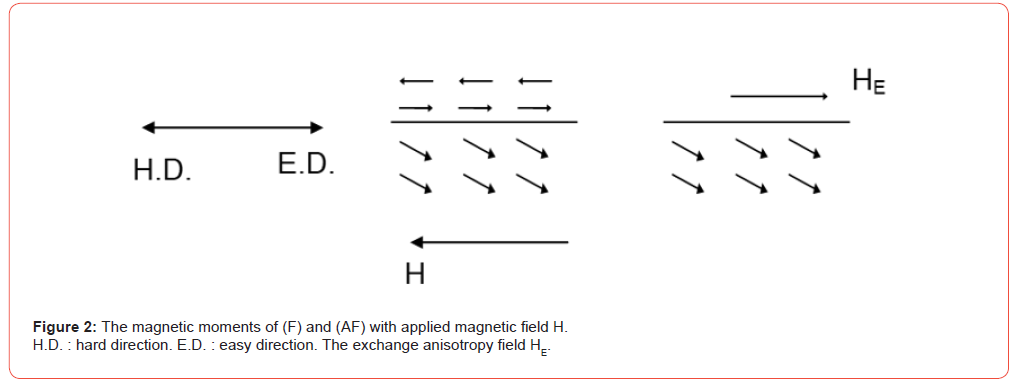
The bilayer consisting of an antiferromagnetic (noted (AF)) and a ferromagnetic (F) thin film is shown in Figure 1a. The magnetic moments of (AF) are parallel to those of (F) at the interface (see Figure 1b). There is an exchange coupling between the moments of both layers at the interface. If an external field H is applied to the system opposite to the (F) moments (see Figure 2), the (AF) moments are not affected by the H field, because of the strong (AF) magnetic anisotropy. Then, the interaction, at the interface, between the (F) and (AF) moments will not allow the (F) magnetic moments to rotate in the direction of H. Thus, the (F) magnetic moments prefer to align in the interfacial (AF) moment direction, i.e from left to right in Figure 2 which becomes an easy direction for the moments (noted E.D. in Figure 2). On the other hand, the (F) moments do not prefer the H direction, i.e., the right to left direction which is thus a hard direction (noted H.D. in Figure 2). Therefore, the interaction (F)/(AF) has introduced a unidirectional anisotropy, different from the usual uniaxial anisotropy where, for a given axis, both directions are equivalent. Here, for the same axis, the left to right (E.D.) and the right to left (H.D.) directions are not equivalent. This new unidirectional anisotropy is called exchange anisotropy. This phenomenon was first observed in the Co/CoO bilayer [1] (Co being ferromagnetic and the Co oxide, CoO, is antiferromagnetic).
Note also that the moments at the interface are aligned as
shown in Figure 1b. This can be done by some experimental procedures.
One may cite for instance
(i) Applying a magnetic field during the deposition of the two
films
(ii) Annealing the bilayer to a temperature T greater than the Néel
temperature TN of (AF) (where the moments of the (AF) thin
film become randomly oriented) and then cooling the sample
in a magnetic field. These methods will ensure that the
moments at interface will be aligned, parallel to the applied
field. A study was reported about the effect of the magnitude
of the applied magnetic field during the film deposition on the
magnetic properties of Co/FeMn bilayers [21]. The effect of
the configuration and the magnitude of the magnetic field H,
during the elaboration of the samples, on the magnetic properties
of magnetron sputtered NiFe/IrMn was recently studied
[22].
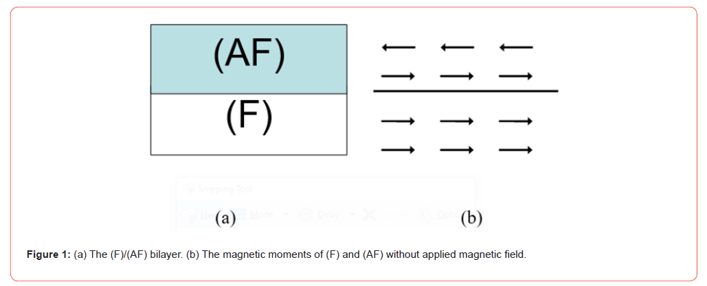
Earlier, experiments were done concerning the annealing (without the application of a magnetic field) and the magnetic annealing (with the application of a magnetic field) of a set of NiFe/ FeMn bilayers, at a temperature equal to 350°C (higher than the Neel temperature TN of FeMn, TN = 220°C). After cooling, for the straight annealing, the exchange anisotropy disappears, while for the magnetic annealing, the exchange anisotropy is restored with the same values as those in the as-deposited samples [23]. There was a study about the effect of heating and cooling in a magnetic field on the exchange anisotropy of Co/FeMn bilayers [24]. In a more recent work [25], it was shown that the exchange anisotropy depends on the direction of the applied field during cooling. Thus, the application of a magnetic field seems to be necessary to induce the exchange anisotropy, either during the film deposition or for the heating and cooling experiment.
The Exchange Anisotropy Field
Definition
One can see that the interaction at the interface which is responsible for the exchange anisotropy can be thought as an internal magnetic field opposite to the external field (see Figure 2). This field is called exchange anisotropy field and noted H E (Figure 2). The H E field will then act as the interaction and will maintain the (F) moments in its direction (the left to right or easy direction).
About the technological application of the exchange anisotropy field HE, one may cite two of them. As pointed out in the introduction, it was proposed to be used in the magnetoresistive head (MR head) [26]. In this MR head used to read the information from a medium, the variation of the electrical resistance R of the ferromagnetic material (the MR head) reproduce exactly the magnetic domains of the medium. However, if the working point is at H = 0, the signal (when the head goes from one domain to the other) is small. The idea was to apply a constant magnetic field H to the head (exchange bias), the working point will be at H and the signal will be stronger. The exchange anisotropy field HE may play this constant field on the head. Another application is the method to avoid the Barkhausen noise. In a multidomain material, the change in the magnetization direction is achieved by domain wall motion. If there is a defect in the material, it will act as a barrier to the smooth motion of the domain wall. When H is increased, a jump of the wall occurs which results in a noise, called the Barkhausen noise, in the output. In order to avoid this noise, it is preferable to work with a single domain material (the change in the magnetization direction will be by rotation.) by permanently applying a magnetic field to the ferromagnetic material; this can be achieved by the use of the HE field.
The Exchange Anisotropy Field HE Characteristics
Variation With the (F) Thin Film Thickness
It was observed that HE varies as 1/tF. This makes sense, since
the interaction is interfacial; the thinner the film, the more important
is the effect of the surface or the interface. From a very simple
calculation, one can find this variation. Assume that there are N
magnetic moments per unit surface of the interface; let
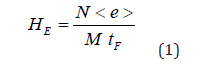
One can see, from this very simplistic reasoning, that the 1/tF variation is found. More elaborated calculations would give this kind of variation. Experimentally, HE is found to vary as 1/tF, however the experimental value is always smaller than the theoretical one. This is will be discussed in the next section.
Variation With the (AF) Thin Film Thickness
Experimentally, it was found that HE is zero below a critical (tAF) C thickness. Beyond (tAF)C, HE increases and levels off to a constant value as tAF is increased further. Thus, a minimal number of (AF) atomic planes is needed to establish the exchange coupling between the (F) and (AF) moments. Once the coupling is set, the HE value does not change for larger tAF. In a study of the NiFe/CrMnPt9 bilayer, it was found that HE starts to have a non vanishing value for tAF of about 20 nm, increases with tAF and levels off to a constant value beyond tAF of about 30 nm [31,32]. In the NiFe/NiO bilayer, the field HE vanishes for a tAF less than about 20 nm, then increases and reaches a constant value beyond 50 nm [33].
Variation with Temperature
One expects that the exchange coupling between the (F) and (AF) would disappear and hence HE vanishes when the temperature T reaches the Neel temperature TN of (AF) where the magnetic moments will be randomly oriented (the material becoming paramagnetic for T > TN). However, what is observed is that the exchange anisotropy decreases, indeed, with increasing temperature and vanishes (HE = 0) at a temperature T = TB, below TN (before the transition of the (AF) to the paramagnetic state); TB is called the blocking temperature. For instance, It was found in the NiFe/FeMn system [33], TB (NiFe/FeMn) = 150°C, while the Curie temperature of NiFe is TC (NiFe) = 550°C, and the Neel temperature of FeMn is TN (FeMn) = 225°C. In the Fe3 O4 /CoO bilayer, with a 30 Å thick CoO [34], it was reported that TB = 240°K, while TN (CoO) = 450°K. More recently, it was observed that the blocking temperature value can be related to the grain size in the (AF) layer [35].
The interface (F)/(AF)
In the static (AF) model, the assumption is that the uncompensated spins in (AF) at the interface are not affected by the applied field, they are pinned along the (AF) easy direction (Figure 3a). The existence of these uncompensated spins is attributed to some properties [36] such as, for instance, the grain size and grain boundaries as well as the roughness of the interface. As pointed out in the introduction, several models [13,20] have been proposed to describe the (F)/(AF) interface in order to explain the different behaviors of the exchange anisotropy observed in this system.
It was observed, for instance, that the theoretical exchange anisotropy field value is larger than the measured one. This was attributed, among other factors, to the fact that not all magnetic moments, at the interface, contribute to the value of HE. The assumption is that there are grains where the magnetic moments are coupled while in other sites there is no coupling leading to a smaller interaction and hence a smaller HE value [36].
In fact, the relationship between the exchange anisotropy behavior and the structure and morphology of the interface is well established [37-42]. The layer deposition order [39,40] as well as the surface roughness in NiFe/IrMn [40] and in NiFe/NiO [41] affect the exchange anisotropy value. The surface morphology and the exchange anisotropy were studied in NiFe/IrMn bilayer deposited on a flexible substrate [42]. Also, the interdiffusion is not to be excluded. In experiments on NiFe/FeMn and NiFe/α -Fe2 O3 samples [43], it was found that for the former, the interface is relatively sharp; while for the latter, a layer was formed at the interface by interdiffusion. This intermediate layer was detected by Ferromagnetic Resonance (see Section 5.3) and its magnetic properties are found to be different from NiFe (Permalloy). Incidentally in these NiFe/ α -Fe2 O3 samples, the measured exchange anisotropy field is weak. Chemical analysis show that the layer consists ofα -Fe and Fe3 O4 due to the diffusion of Fe from NiFe intoα -Fe2 O3 [43].
In another model, it is assumed that a domain wall exists in the (AF) layer [44,45]. This arises from the fact that the (AF) moments at the interface may rotate with the (F) magnetic moments because of a relatively strong exchange coupling between the (F) and the (AF) moments. However, the (AF) moments try to remain aligned along the easy direction due to the (AF) anisotropy; this leads to the creation of a domain wall (see Figure 3b).
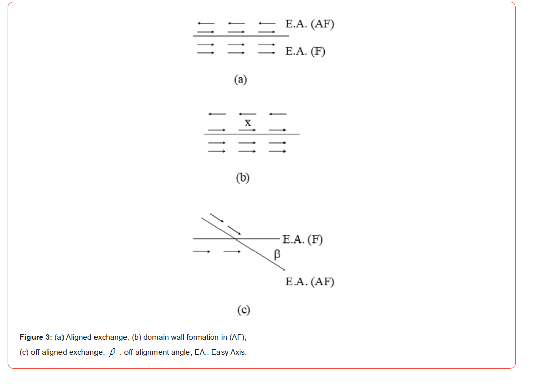
As for the relative directions of the easy axes in (F) and (AF), two situations are found. When the (AF) and the (F) easy axes are parallel (see Figure 3a), the case is referred to as the ‘aligned’ exchange anisotropy. The direction of the exchange field H E is thus along this common easy axis of the (F) and (AF). Another situation is termed as the off-aligned exchange anisotropy. In this case, the easy axis of the (AF) layer (the unidirectional anisotropy axis or the H E direction) and the (F) easy axis are not parallel but make a β angle between them; β is called the off-aligned angle (see Figure 3c). An angular variation [46-50] of H E was experimentally observed and this off-aligned model can explain such a variation. This case has been seen in many systems, a β angle equal to 90° (a perpendicular exchange anisotropy) was observed for Fe3 O4/CoO [34] and for Fe–FeF2 [50]. In La0.7Sr0.3MnO3 /NiO bilayer, the authors [51] observed a transition of the exchange anisotropy from in-plane to out-of-plane as the substrate is changed. This transition is believed to be due to the strain induced by the substrate which leads to a reorientation of the NiO spins at the interface. In some spintronic devices, the out-of-plane anisotropy is preferred [51].
Methods of Detection and Measure of HE
As pointed out before, the hysteresis curve was used and remains the most common experimental method to detect and measure the exchange anisotropy. Other techniques have been used since to investigate the exchange anisotropy. Among these experimental methods, one may cite, for instance, the Brillouin Light Scattering (BLS) technique [41,52], the Magneto-Optic Kerr Effect (MOKE) set-up [53,54] and the susceptibility measurements [55- 57]. In this latter work [57], the effect of the easy axis distributions on the exchange anisotropy field HE was discussed to explain the difference observed in the HE values when measured by two methods based on the ac susceptibility and the DC measurements.
In the present work, focus will be on three techniques, starting from the most popular one, the shifted hysteresis curve, then the torque curve and finally the Ferromagnetic Resonance. For each of these techniques, the method will be briefly described and the important features leading to the detection of the exchange anisotropy will be given along with the main relations allowing to measure the exchange anisotropy field.
Note that the exchange anisotropy is studied in the (F)/(AF) bilayer alone and also when the (F)/(AF) is part of a multilayer [58- 67] such as the Magnetic Tunnel Junction (MTJ) systems [59,60,63- 65]. The phenomenon is also observed in other systems such as in hard/soft ferromagnetic bilayers [68] and in nanoparticles [69-71]. The authors [70] observed a shifted hysteresis curve in ferromagnetic nanoparticles; the exchange anisotropy is attributed to the existence of grains with different easy axis directions (the random anisotropy) which leads to hard and soft areas within the sample. In ferrite nanoparticles, the authors [71] attribute the exchange anisotropy to the coupling between the spins at the ferrimagnetic and spin glass-like interface.
In the following, the bilayer thin films will be taken in the xOy plane. The magnetization M of the (F) layer is defined in spherical coordinates by the angleθ andϕ . The applied magnetic field H is taken to be in the film plane making an angle ϕH with the x-axis. The total energy of the system per unit volume can then be written as

The first term in Eq. (2) is the Zeeman term, i.e. the interaction of M with the applied magnetic field H. The second is the shape anisotropy energy for a thin film. The third term is the energy due to the exchange anisotropy field H E, β being the off-alignment angle (for the aligned exchange anisotropy, β = 0). The fourth term is the in-plane magnetic anisotropy with constant Kup , Kup is taken to be positive, i.e. the x-axis is the easy direction of the magnetization. The fifth term is the out-of-plane uniaxial magnetic anisotropy with constant K, K is positive so that the normal to the film (the z-axis) is the easy axis (perpendicular anisotropy). Note that the anisotropies described in the last two terms may (or may not) exist in a given system. Moreover other anisotropies may exist such as the magneto-crystalline anisotropy energy with an anisotropy axis tilted from the normal of the film, or the cubic anisotropy which will be mentioned in some cases in the following analysis.
Hysteresis Curve
The exchange anisotropy is detected when a shifted hysteresis M vs H curve is obtained; while for a single (F) thin film, the hysteresis curve is symmetric with respect to the M axis. The shifted curve is becoming the signature of the exchange anisotropy. In the following, analytical expressions will be given for the hysteresis curve in some situations.
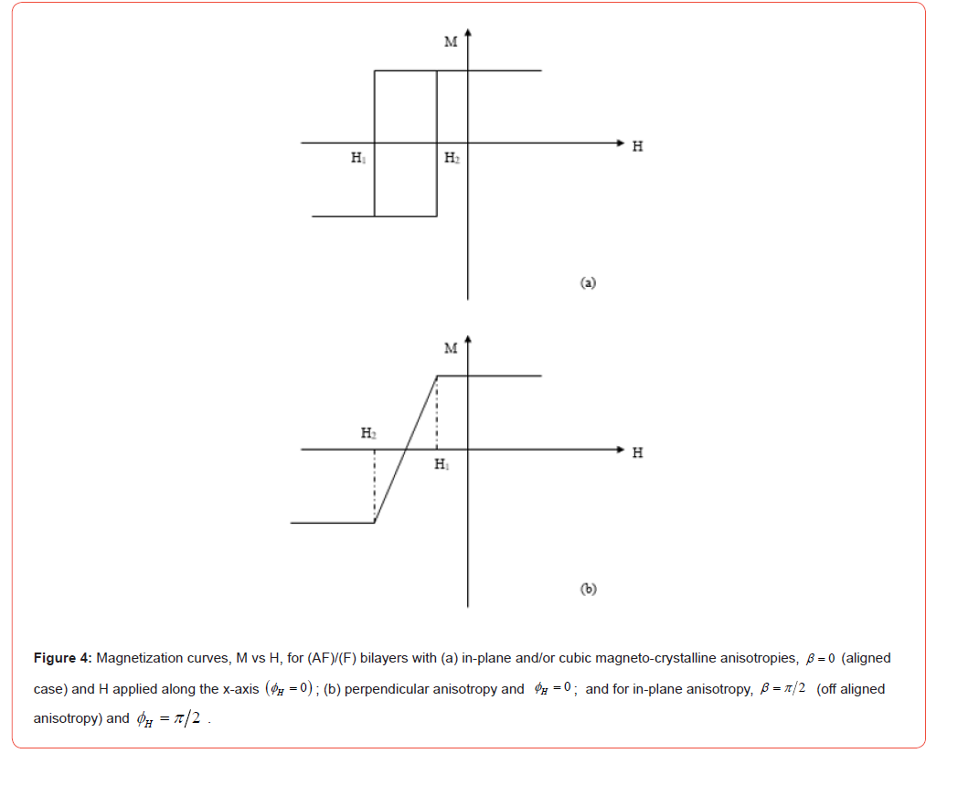
The shifted M vs H curve can be described in a straightforward manner. The applied magnetic field is taken to be along the x-axis, in the forward direction ( ϕH = 0), the direction of the exchange anisotropy field H E for the aligned case; then in the reverse direction (ϕH =π ) . One can minimize the total energy (Eq. 2) and find the equilibrium positions of the magnetization M of the (F) thin film for each value of H between the saturation fields in the forward and reverse directions. This has been done; the shifted hysteresis curve is obtained (see Figure 4).
The switching fields H1 and H2 depend on the anisotropy present in the film. For the in-plane anisotropy only, H1 and H2 are given by
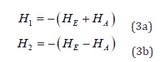
Here HA is the in-plane anisotropy field, i.e. HA = 2Kup/M. The curve (see Figure 4a) is shifted by HE and the width of the curve is equal to 2 HA.
If the cubic magnetocrystalline anisotropy [79] is added, then
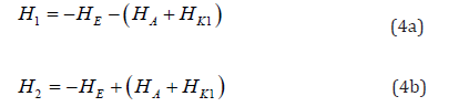
where HK1 = 2K1/M, K1 being the first order cubic anisotropy constant. The width in this case is equal to 2(HA + HK1), but the shift of the curve in the H axis is still HE (see Figure 4a).
When there is a perpendicular anisotropy with a constant K (positive), the corresponding anisotropy field is HK = 2K/M. If (HK - 4π M) is positive, then the uniaxial magnetocrystalline anisotropy is strong enough to overcome the effect of the shape anisotropy and the magnetization will be tilted from the plane for low field; M will be in the film plane beyond the saturation fields in the forward (ϕH= 0) and reverse (ϕH=π ) directions. These saturation fields H1 and H2 are now given by

Thus, between H1 and H2, the magnetization will rotate from out-of-plane to the plane directions as H is increased. This will give a shifted hard axis M-H loop (see Figure 4b). The shift is equal to HE and the interval between H1 and H2 is equal to 2(HK− 4π M ) . Note that the straight line between H1 and H2 is given by the equation.
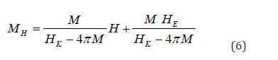
MH is the magnetization component value along the applied field direction. The crossing of the curve with the H axis (where MH = 0) is given by H = -HE, the curve is shifted by an amount equal, once again, to HE. From the slope of the straight line and the magnetization at H = 0, one may derive the perpendicular anisotropy field HK and the magnetization M; of course, these parameters could also be inferred from the measure of the saturation fields (Eqs. (5a) and (5b)).
For the off-aligned case, as pointed out before, the phenomenon was observed when doing magnetization curves for different applied field directions in the film plane. There are many works where the misalignment is detected and measured from hysteresis curvebased methods [72-78]. Note that, contrary to the aligned case where the equilibrium conditions would give analytical formula of the switching and saturation fields and hence the magnetization curve, for the off-aligned case, there are no analytical formula, the equations have to be numerically solved. However, forβ =π/2 (the perpendicular coupling) and when the magnetic field is applied at ϕH =π/2 (along the H E direction) then, one may obtain analytically, the saturation fields and the magnetization curve. With the same procedure as before, the saturation fields H1 and H2 are given by:

A hard axis curve is obtained (see Figure 4b). The shift is, once again, equal to HE and the interval between H1 and H1 is equal to 2 HA, the straight line between H1 and H2 is given by the equation
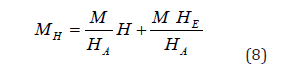
Note that in the above relations, the magnetic fields H1 and H2 are written as algebraic expressions, they can be positive if the fields are in the forward direction (ϕH =0) and negative when they are oriented in the reverse one (ϕH = π). On the other hand, HE, HA and HK are positive quantities, while the cubic anisotropy constant K1 (and HK1) can be positive or negative.
The Torque Method
The torque method is widely used to measure the anisotropy constants of a ferromagnetic thin film. In this method the applied magnetic field is rotated in the plane of the film (the present study) or out of plane. Then the torque exerted on the magnetisation M by the magnetic field H, T = M∧H , is recorded. The torque method has been used to detect and measure the parameters pertaining to the exchange anisotropy such as the exchange anisotropy field HE and the off-alignment angle β (for the off-aligned case) [79,82].
The torque expression has been derived from the total energy of the system. Note that T = M∧H is the torque per unit volume; in a torque magnetometer, the recorded quantity is the total torque, so one has to multiply the above quantity by the sample volume V. The total torque is found as:

More often the maximum torque curve is used to measure the magnetic anisotropy constants of a thin film. Another interesting feature that can be used is the slope of the curve at a particular H value. The slope method has been applied to determine the field HE and the off-alignment angle β [79-82] as is discussed below. It was also used to measure the magnetic coupling in a trilayer system [83].
The slope of the torque curve is defined as the derivative of the torque T with respect to the applied field angle ϕH ; the slope S is found to be

Now let us discuss how to find the parameters describing the exchange anisotropy (the field HE and the off-alignment angle β ) from the slope which can be experimentally measured.
For a single thin film without exchange anisotropy (HE = 0); the torque curve (Eq. (9)) is the usual sin 2ϕ curve expected for a ferromagnetic thin film with in-plane anisotropy and with the magnetic field H applied in different directions in the film plane [79]. For the applied field angle in the 0 - 2π interval, the torque T vanishes at 0,π/2,π , π/3 2 and 2π (i.e at nπ/2 , where n is an integer.) [79,81,82]. On the other hand, for (F)/(AF) bilayer with exchange anisotropy and in the aligned case (β = 0) , the curve given by Eq. (9) is a distorted sinϕ curve, where T vanishes now at applied field angle equal to 0,π and 2π (i.e at nπ ) different from the single thin film [79]. This shape may be a signature of the presence of exchange anisotropy. Moreover, for the off-aligned case (β ≠ 0o ) ; the torque curve (inferred from Eq. (9)) is shifted compared to the aligned case (β = 0) [81,82]. The amount of shift (which will noted α0 in the subsequent analysis) is related to the off-aligned angle β and can be used to experimentally derive the β angle. This effect of the off-alignment will be discussed in the following.
First, for the aligned case (β = 0) , then the following relation giving HE as the function of the slope S(0), at j ϕH =ϕ =0 , is found:

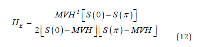
Eq. (11) can be used to measure HE if HA is known. Alternatively, if HA is unknown, one can still obtain experimental values by measuring the slopes at ϕH =0 and ϕH =π . Once the slopes S(0) and S (π ) are measured, the field HE is then given by
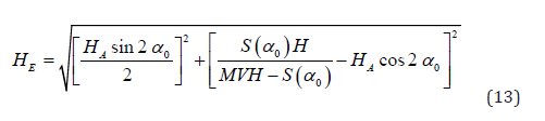
Second, for the off-aligned case (non vanishing α0 ), one has then to determine HE and the α0 angle. Recall that for the aligned case, the torque vanishes at ϕH =0,T (ϕH =0). On the other hand, for the off-aligned case, T does not vanish at ϕH =0 , but at another angle ϕH noted here α0 ; thus the torque curve in the off-aligned case is shifted compared to that of the aligned case, the amount of shift is 0 α which can be measured from an experimental torque curve. With the measure of α0 and the slope at α0 S(α0 ) 0 0 α , α , the exchange anisotropy field is given by
Knowing HE, one can derive the off aligned angle b by the following relation

Note that, if one puts α0 = 0 (aligned case) in Eq. (13), it will correctly reduce to Eq. (11) as expected and Eq. (14) gives β = 0 . One can see that by doing one experimental torque curve, one can deduce the exchange anisotropy field HE and the β angle (if it is the off-aligned case), by measuring the slope at particular points and the shift of the curve if any.
Note finally, if the in-plane anisotropy field HA is very small compared to HE and H, then from Eq. (13), one can make some approximations and gets:
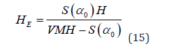
and Eq. (14) will give β =α0 (in this case, the measured shift is equal to the off-alignment angle).
Ferromagnetic Resonance (FMR)
Ferromagnetic Resonance (FMR) is the absorption of electromagnetic energy by a ferromagnetic material subject to an external DC magnetic field H. The material experiences thus the effect of a constant field H and a time varying (rf or microwave) field h. When the value of the frequency of h and the magnitude of H satisfy a condition (the resonance condition), an absorption peak is observed in a FMR experiment. Generally, the derivative of the absorption power is displayed.
In a FMR experiment, one can fix the frequency and vary the applied field H or fix the field H and vary the frequency. The resonance condition between the (angular) frequency γ and the applied field H includes some of the intrinsic magnetic properties of the sample such that the magnetic anisotropy and the magnetogyric ratio α or the g factor.). Moreover, the linewidth of the peak is related to the damping.
The FMR technique has been widely used to investigate a variety of phenomena in thin film and magnetic multilayers [84-88], including the exchange anisotropy in bilayer (AF)/(F) [43,89-106]. In the FMR, the spectrum is characterized by the number, the position, the linewidth and the intensity of the peaks. These features may lead to the determination of the different anisotropies present in the system (including the exchange anisotropy), the g factor and the damping constant. Note also that one of the advantages of FMR is that it may single out different regions with different magnetic properties. If a region, for instance, a layer at the interface, is characterized by different magnetic properties than the whole film, then besides the main peak corresponding to the film, an additional peak may appear in the spectrum which will give the magnetic characteristics of this region; that is how the formation of the layer at the interface of the NiFe/α -Fe2 O3 bilayer was detected and characterized [43].
The resonance condition can be derived, within the energy formulation, by the general formula

Where ω is the resonant (angular) frequency, γ is the magnetogyric ratio. Eθθ , E ϕϕ and Eθϕ are the second derivatives of the total energy with respect to the variables θ and ϕ specifying the equilibrium position of the magnetization. The resonance condition can then be found from Eqs. (2) and (16). For (F) characterized by an in-plane anisotropy, the relation is given by

Recall that for this case, it is assumed that the magnetization remains in the film plane (θ =π 2) due to the absence of perpendicular anisotropy, the strong shape anisotropy and the fact that the external magnetic field H and HE are in the film plane. The magnetization angle ϕ is given by the equilibrium position

For the aligned case, β = 0 ; if one is using a fixed frequency- variable H field, then one may measure the resonant field, HR, for H applied in the forward direction (ϕH= 0) , i.e. HR(0), and in the reverse direction HR( π) . In this case it is found that the exchange anisotropy field is simply given by

Note that for a thin film with uniaxial anisotropy, HR (0) and HR (π ) are equivalent. The fact that they are different is an indication of the existence of exchange anisotropy with the exchange anisotropy field given by Eq. (19).
If one is using a fixed H field-a variable frequency set-up, then one measure the resonant frequency with H applied at ϕH =0 , i.e. ω (0) and at ϕH =π , i.e. ω (π ) . The exchange anisotropy field can then be derived by

Note that for the use of Eq. (20), in the FMR experiment, the applied field H must have the same magnitude for both directions ( ϕH =0 and ϕH =π and be strong enough to insure the saturation, i.e. the magnetization M along H (ϕ = 0 and ϕ =π Thus, from the mode position in the FMR spectra, one can detect the exchange anisotropy and measure the exchange anisotropy field HE.
Another situation is the (F) film with perpendicular anisotropy; it is assumed that HK is positive and strong enough to pull the magnetization towards the z direction and there is no in-plane anisotropy. In this case, as discussed in the previous subsection pertaining to the hysteresis curve, the magnetization M does not lie in the film plane for all H values. There are two regions.
First, for the saturated case where H is greater than the saturation field, then θ =π 2 , and the resonance condition is given by

The exchange anisotropy field is then given by
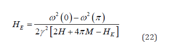
Second, for the unsaturated case with H2<H< H1 (H1 and H2 are
the saturation fields given by Eqs. (5a) and (5b)), the magnetization
is out of the plane, making a θ angle with z axis. In this case, the
resonance condition is found to be one measure the resonant frequency with H applied at ϕH =0, i.e.
ω (0) and atϕH =π , i.e. ω (π ) . The exchange anisotropy field can
then be derived by
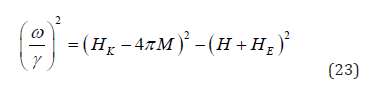
The exchange anisotropy field HE can be derived from Eq. (23); it can be measured through the following relation
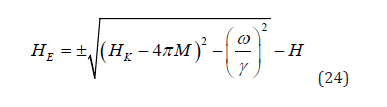
In Eq. (24) above, the (+) sign applies for -HE<H<H1, the H values
corresponding to the upper part of the straight line in Fig. 4b
(the positive M values); while the (-) sign is to be used for H2<H<-HE,
the lower part of the straight line (or the negative M values). Recall
that H1 and H2 are given by Eqs. (5a) and (5b).
For the off-aligned case ( β is not equal to zero), Eqs. (19) and (20) do not hold anymore. One needs to do FMR experiment, with the field H applied in different directions within the plane and measure, for the same frequency, the resonant field HR for each H ϕ angle. It is found that the HR vs ϕH curve for a bilayer (AF)/(F) with misalignment is shifted with respect to the curve corresponding to the aligned case with the same HE. For the aligned case, as expected, the curve goes from a minimum value of HR at ϕH =0 (the easy direction or the HE direction) to a maximum at ϕH =π (the hard direction). For the off-aligned case, it is found that the minimum resonant field value does not occur at ϕH =0 , but at ϕH= ϕH0. The shift (ϕH0 )is related to the off aligned angle β by a relation which cannot be expressed as an analytical formula for HE (as was the case in the shifted torque curve) but can be numerically solved [97]. This is because, as mentioned in the hystersis curve section, the angles giving the magnetization equilibrium position cannot be given by analytical formula, Eq. (18) has to be numerically solved. However, as for the saturation fields, the β =π/2 case (the perpendicular coupling) and if the applied field is along the H E direction (ϕH =π/2) , then analytical formula can be obtained for the resonance condition in both saturated and unsaturated cases, and hence the H E can be obtained by a simple expression. This analysis is described in the following.
For the saturated case where H is beyond the saturation fields H1 and H2 given by Eqs. (7a) and (7b), then the resonance condition is found to be:

For a fixed frequency-variable applied magnetic field, then the exchange anisotropy field is given by

where HR(3π/2) R H and HR(π/2) are the resonance fields when H is applied along the ϕH =π/2 (90 degrees) and ϕH =3π/2 (370 degrees) directions respectively.
For a fixed applied field-variable frequency set-p, then the exchange anisotropy field is given by

For the unsaturated case with H2<H<H1 (H1 and H2 are the saturation
fields given by Eqs. (7a) and (7b)), the magnetization is not
along the HE direction, i.e. ϕ is not equal to π 2 . In this case, the
resonance condition is found to be
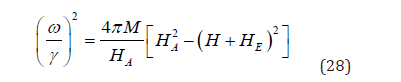
The exchange anisotropy field HE can be derived with the use of the following relation
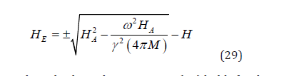
The remark made about the signs in Eq. (24) holds for the signs appearing in Eq. (29) above; and in the present case, H1 and H2 are given by Eqs. (7a) and (7b), respectively
Some remarks can be made about the FMR relations derived above. Some effects related to the magnetic anisotropy were addressed to explain some experimental observations. The rotatable anisotropy was introduced to account for a constant shift in the resonant field when the magnetic field is applied in different directions within the plane [91]. As reported in a work about exchange bias in ferrite nanoparticles [71], the rotatable anisotropy is due to the spins which are not strongly pinned at the interface; it is equivalent to an internal magnetic field which follows the applied field direction. The resonance relations have been discussed here for the system with in-plane anisotropy (the aligned and off-aligned cases) and for the perpendicular anisotropy. Other kinds of anisotropies can be considered by adding the corresponding anisotropy energy in Eq. (2). The cubic magnetocrystalline anisotropy was considered and its effects on the resonance mode (the resonant condition, the linewidth and the intensity of the peaks) were discussed and compared with the in-plane anisotropy case [93,97]. The stress-induced anisotropy was added [100-105]. The titled anisotropy axis case was worked out [106]; in this situation, the anisotropy axis is out-of-plane and tilted from the z-axis with an angleδ ; the effect of δ on the resonance modes was discussed [106]. The perpendicular anisotropy discussed here can be thought as a particular case of the tilted anisotropy axis (by simply putting δ = 0).
Conclusion
The interaction at the interface between a ferromagnetic (F) and an antiferromagnetic (AF) thin films leads to a unidirectional anisotropy called exchange anisotropy. The application of a magnetic field during the film deposition or during a post deposition annealing seems to be necessary to induce the interfacial interaction. The effect is equivalent to an internal magnetic field, the exchange anisotropy field HE. The HE field varies as the inverse of the (F) thickness. The phenomenon starts to be observed when the (AF) thickness, tAF, is greater than a critical (tAF)C value and disappears when the temperature reaches a blocking temperature TB lower than the Neel temperature of (AF). There are some correlations between the HE behavior and the structure, the morphology and the roughness of the films at the interface. The aligned and the off-aligned (or misaligned) cases are considered, depending of the relative directions of the (F) and (AF) easy axes. Three methods for the detection and measure of HE are reviewed.
(i) For the magnetization curve, analytical expressions are derived
for the saturation and the switching fields leading to
the expected shifted hysteresis curve. This has been done for
in-plane, cubic and perpendicular anisotropies and for a 90°
exchange coupling. The shift is equal to HE while the width of
the curve is related to the magnetic anisotropies present in the
film. In some encountered situations, the magnetization curve
is a hard axis like curve with the shift equal also to HE.
(ii) For the torque curve, a method based on the curve slope is
presented; it allows one to determine HE from a single curve
by measuring the slope at some points. For the off-aligned
case, the curve is shifted with respect to the aligned case, the
amount of shift is related to the off-alignment angle β .
(iii) The resonance ferromagnetic (FMR) is the third technique
described here. The resonance conditions are worked out for
different magnetic anisotropies, and for the saturated and unsaturated
situations. The HE value can be determined with H
applied in two different directions, by measuring the resonant
fields (frequencies) for a fixed frequency-variable field set-up
(a fixed field-variable frequency spectrometer). For each of
these three methods, the pertinent relations are given and the
way to determine HE and β is described. Finally, the exchange
anisotropy phenomenon is studied in the (F)/(AF) bilayer
alone and when it is part of the spin valve structure [(AF)/(F)/
non-magn/(F))] used in the giant magnetoresistance (GMR)
heads, in the magnetic recording technology.
Author Contribution Statement
This is a single author paper; I am the only contributor.
Data Availability Statement
All data generated or analysed during this study are included in this published article.
Acknowledgment
None.
Conflicts of Interest
The author declares no conflict of interest.
References
- Meiklejohn W H, Bean C P (1956) New Magnetic Anisotropy Phys Rev 102: 1413.
- Tsang C, Lee K (1982) Temperature dependence of unidirectional anisotropy effects in the Permalloy‐FeMn systems. Appl. Phys 53: 2605.
- Cain W C, Meiklejohn W H, Kryder M H (1987) Effects of temperature on exchange coupled alloys of Ni80Fe20‐FeMn, Ni80Fe20‐αFe2O3, and Ni80Fe20‐ J. Appl. Phys 61: 4170.
- Carey M J, Berkowitz A E (1992) Exchange anisotropy in coupled films of Ni81Fe19 with NiO and CoxNi1−xO. Appl. Phys. Lett 60: 3060.
- Soeya S, Hoshiya H, Fuyama M (1996) Exchange coupling between ferromagnetic fcc Ni81Fe19 and antiferromagnetic bcc CrMnPt films. J. Appl. Phys 80: 1006.
- Li C H, White R L, Wang C P, Antony T C (1998) Exchange anisotropy in Ni82Fe18O {100}/Ni80Fe20 J. Appl. Phys 83: 6816.
- Nogués J, Schuller I K (1999) Exchange bias. Magn. Magn. Mater 192: 203.
- Aley N P, O Grady K (2011) Compositional dependence of antiferromagnetic anisotropy in IrMn/CoFe exchange bias systems. J. Appl. Phys. 109: 07D719.
- Ehrmann A, Blachowicz T (2011) Adjusting exchange bias and coercivity of magnetic layered systems with varying anisotropies. Appl. Phys 109: 083923.
- Jenkins S, Fan W J, Gaina R, Chantrell R W, Klemmer T, et al. (2020) Atomistic origin of exchange anisotropy in noncollinear γ−IrMn3–CoFe bilayers. Rev. B 102: 140404(R).
- Vergès M, Kumar V, Lin P H, Mangin S, Lai C H, et al. (2020) Role of induced exchange bias in zero field spin–orbit torque magnetization switching in Pt/[Ni/Co]/PtMn. AIP Advances 10: 085320.
- Raza S A, Correa M A, Gonzalez-Chavez D E, Bohn F, Sommer R L, et al. (2021) Dynamic magnetic response of exchange-biased Co2FeAl/IrMn nanostructures. Lett 18: 129518.
- Gökemeijer N J, Penn R L, Veblen D R, Chien C L (2001) Exchange coupling in epitaxial CoO/NiFe bilayers with compensated and uncompensated interfacial spin structures. Rev. B 63: 174422.
- Grechnev A G, Kovalev A S (2009) Magnetization field-dependences and the "exchange bias” in ferro/antiferromagnetic systems. I. Model of a bilayer ferromagnetic. Low Temperature Physics 35: 476.
- Wu J, Park J S, Kim W, Arenholz E, Liberati M, et al. (2010) Direct Measurement of Rotatable and Frozen CoO Spins in Exchange Bias System of CoO/Fe/Ag (001). Rev. Lett 104(21): 217204.
- Malozemoff A P (1988) Mechanisms of exchange anisotropy (invited). J. Appl. Phys 63: 3874.
- Chen G, Collette D, Urazhdin S (2020) Experimental demonstration and analysis of random field effects in ferromagnet/antiferromagnet bilayers. Phys. Rev. B 101: 144427.
- Maniv E, Murphy R A, Haley S C, Doyle S, John C, et al. (2021) Exchange bias due to coupling between coexisting antiferromagnetic and spin-glass orders. Nature Physics 17: 525.
- Yoo W, Choo S, Jo S, You C Y, Hong J Il, et al. (2021) The Azimuthal Dependence of Exchange Bias Effect and its Analysis by Spin Glass Model in Ni0.8Fe0.2/CoxNi1−xO Bilayers. IEEE Access 9: 21315.
- Nayak S, Manna P K, Singh B B, Bedanta S (2021) Effect of spin glass frustration on exchange bias in NiMn/CoFeB bilayers. Phys Chem Chem Phys 23: 6481.
- Dzhun I O, Dushenko S A, Chechenin N G, Konstantinova E A (2011) The dependence of magnetic properties of Co/FeMn bilayer structure on the magnitude of magnetic field applied during the layer deposition. J. Phys.: Conf. Ser 303: 012104.
- Gritsenko C, Omelyanchik A, Berg A, Dzhun I, Chechenin N, et al. (2019) Inhomogeneous magnetic field influence on magnetic properties of NiFe/IrMn thin film structures. Magn. Magn. Mater 475: 763.
- Layadi A, Lee J W, Artman J O (1988) FMR and TEM studies of annealed and magnetically annealed thin bilayer films. J. Phys 64: 6101.
- Dzhun I O, Dushenko S A, Chechenin N G, Konstantinova E A (2011) Temperature dependence of exchange bias in Co/FeMn-structure induced by heating and cooling in magnetic field. Phys.: Conf. Ser 303: 012103.
- Choi S, Lee K J, Choi S, Chongthanaphisut P, Bac S K, et al. (2021) Controllable Exchange Bias Effect in (Ga, Mn) As/ (Ga, Mn)(As, P) Bilayers with Non-Collinear Magnetic Anisotropy. IEEE Transactions on Magnetics 57: 9133138.
- Cain W C, Lee J W, Koeppe P V, Kryder M H (1988) Exchange coupled NiFe-TbCo thin films for use in self-biased magnetoresistive heads. IEEE Transactions on Magnetics 24: 2609.
- Parkin S S P, Roche K P, Samant M G, Riche P M, Beyers R B, et al. (1999) Exchange-biased magnetic tunnel junctions and application to nonvolatile magnetic random access memory. J. Appl. Phys 85: 5828.
- Heinrich B (2000) Magnetic nanostructures. From physical principles to spintronics. Can. J. Phys 78:
- Heigl M, Vogler C, Mandru A O, Zhao X, Hug H J, et al. (2020) Microscopic Origin of Magnetization Reversal in Nanoscale Exchange-Coupled Ferri/Ferromagnetic Bilayers: Implications for High Energy Density Permanent Magnets and Spintronic Devices. ACS Appl. Nano Mater 3: 9218.
- Sort J, Suriñach S, Muñoz J S, Baró M D, Nogués J, et al. (2002) Improving the energy product of hard magnetic materials. Phys. Rev. B 65: 174420.
- Xi H, White R M (2000) Antiferromagnetic thickness dependence of exchange biasing. Phys. Rev. B 61:
- Xi H, White R M (2000) Critical thickness effect in the exchange-coupled NiFe/CrMnPtx bilayer system. Phys. Rev. B 61: 1318.
- Soeya S, Nakamura S, Imagawa T, Narishige S (1995) Rotational hysteresis loss study on exchange coupled Ni81Fe19/NiO films. J. Appl. Phys 77: 5838.
- Ijiri Y, Borchers J A, Erwin R W, Lee S H, Van der Zaag P J, et al. (1998) Perpendicular Coupling in Exchange-Biased Fe3O4/CoO Superlattices. Rev. Lett 80: 608.
- Dobrynin A N, Warin P, Vorobiev A, Givord D (2021) On the origin of positive exchange bias and coercivity enhancement in proximity to the blocking temperature. J. Magn. Magn. Mater 520: 166707.
- Takano T, Kodama R H, Berkowitz A E, Cao W, Thomas G, et al. (1997) Interfacial Uncompensated Antiferromagnetic Spins: Role in Unidirectional Anisotropy in Polycrystalline Ni81Fe19/CoO Bilayers. Rev. Lett 79: 1130.
- Merkel M, Huhnstock R, Reginka M, Holzinger D, Vogel M, et al. (2020) Interrelation between polycrystalline structure and time-dependent magnetic anisotropies in exchange-biased bilayers. Phys. Rev. B 102: 144421.
- Xu M, Lu Z, Yang T, Liu C, Cui S, et al. (2002) Relation between microstructures and magnetic properties upon annealing in Fe50Mn50/Ni80Fe20 films. Appl. Phys 92: 2052.
- Shanova E I, Dzhun I O, Chechenin N G (2014) Exchange bias in Ferromagnetic/ Antiferromagnetic bilayer systems with varying microstructure and sequence of layer deposition. Inorganic Materials: Applied Research 5: 89.
- Shanova E I, Dzhun I O, Chechenin N G (2014) Influence of surface roughness and deposition order on exchange bias in bilayer structures NiFe/IrMn. EPJ Web of Conferences 75: 05010.
- Rezende S M, Azevedo A, Lucena M A, de Aguiar F M (2001) Anomalous spin-wave damping in exchange-biased films. Phys. Rev. B 63: 214418.
- Wang Z, Zhou Z, Cheng W, Jiang D, Zhan Q, et al. (2020) Surface morphology and exchange bias of wrinkled NiFe/IrMn bilayers grown on polydimethylsiloxane. Magn. Magn. Mater 513: 167126.
- Layadi A, Cain W C, Lee J W, Artman J O (1987) Investigation of Anisotropy By Ferromagnetic Resonance (FMR) in Exchange-Coupled Bilayer Films. IEEE Transactions on Magnetics 23: 2993.
- Koon N C (1997) Calculations of Exchange Bias in Thin Films with Ferromagnetic/ Antiferromagnetic Interfaces. Phys. Rev. Lett 78: 4865.
- Mauri D, Siegmann H C, Bagus P S, Kay E (1987) Simple model for thin ferromagnetic films exchange coupled to an antiferromagnetic substrate. J. Appl. Phys 62: 3047.
- Ambrose T, Sommer R L, Chien C L (1997) Angular dependence of exchange coupling in ferromagnet/antiferromagnet bilayers. Phys. Rev. B 56: 83.
- Xi H, Kryder M H, White R M (1999) Study of the angular-dependent exchange coupling between a ferromagnetic and an antiferromagnetic layer. Appl. Phys. Lett 74: 2687.
- Nogues J, Moran T J, Lederman D, Schuller I K, Rao K V, et al. (1999) Role of interfacial structure on exchange-biased FeF2−Fe. Phys. Rev. B 59: 6984.
- Xi H, White R M (1999) Angular dependence of exchange anisotropy in Ni81Fe19/CrMnPtx bilayers. J. Appl. Phys 86: 5169.
- Moran T J, Nogues J, Lederman D, Schuller I K (1998) Perpendicular coupling at Fe–FeF2 interfaces. Phys. Lett 72: 617.
- Wu Y, Wang Z, Liang Y, Zhang Z (2020) Strain-induced exchange bias transition at La7Sr0.3MnO3/NiO interface. Journal of Alloys and Compounds 819: 153022.
- Mathieu C, Bauer M, Hillebrands B, Fassbender J, Güntherodt G, et al. (1998) Brillouin light scattering investigations of exchange biased (110)-oriented NiFe/FeMn bilayers. J. Appl. Phys 83: 2863.
- Tillmanns A, Oertker S, Beschoten B, Güntherodt, G, Eisenmenger J, et al. (2008) Angular dependence and origin of asymmetric magnetization reversal in exchange-biased Fe/FeF2(110). Phys. Rev. B 78: 012401.
- Zhan Q f, Krishnan K M (2010) Angular dependence of magnetization reversal process in exchange biased epitaxial MnPd/Fe bilayers. J. Appl. Phys 107: 09D703.
- Ström V, Jönsson B J, Rao K V, Dahlberg D (1997) Determination of exchange anisotropy by means of ac susceptometry in Co/CoO bilayers. J. Appl. Phys 81: 5003.
- Spinu L, Stancu Al, Kubota Y, Ju G, Weller D (2003) Vectorial mapping of exchange anisotropy in IrMn/FeCo multilayers using the reversible susceptibility tensor. Phys. Rev. B 68: 220401(R).
- Geshev J, Nicolodi S, Pereira L G, Schmidt J E, Skumryev V, et al. (2008) Impact of magnetization easy-axis distributions on the ferromagnet-antiferromagnet exchange-coupling estimation. Phys. Rev. B 77: 132407.
- Carey M J, Berkowitz A E, Borchers J A, Erwin R W (1993) Strong interlayer coupling in CoO/NiO antiferromagnetic superlattices. Phys. Rev. B 47(15): 9952-9955.
- Layadi A (2005) Study of the resonance modes of a magnetic tunnel junction-like system. Rev. B 72: 024444.
- Layadi A (2006) Analytical expressions for the magnetization curves of a magnetic tunnel junction-like system. J. Appl. Phys 100: 083904.
- Sun L, Xing H (2008) Angular dependence of longitudinal and perpendicular exchange biases in FeMn/(FeNi/FeMn)n multilayers. J. Appl. Phys 104: 043904.
- Choi H C, You C Y, Kim K Y, Lee J S, Shim J H, et al. (2010) Antiferromagnetic layer thickness dependence of noncollinear uniaxial and unidirectional anisotropies in NiFe/FeMn/CoFe trilayers. Rev. B 81: 224410.
- Layadi A (2015) A theoretical investigation of Ferromagnetic Resonance Linewidth and damping constants in coupled trilayer and spin valve systems. AIP Advances 5: 057113.
- Layadi A (2016) Resonant and switching fields for a weakly coupled magnetic tunnel junction system. SPIN 6: 1640011.
- Layadi A (2018) Analytical expressions for the Ferromagnetic Resonance mode intensity and linewidths for a weakly coupled magnetic tunnel junction system. J. Appl. Phys 124: 143901.
- Xiaodan Chi, Yong Hu (2020) Improvement and stabilization of exchange bias in ferromagnet/antiferromagnet/ferromagnet trilayers. Nanotechnology 31(12): 125703.
- Svalov A V, Kudyukov E V, Lepalovskij V N, Gorkovenko A N, Stepanova E A, et al. (2021) Exchange bias in FeNi/FeMn/Gd–Co trilayers: The role of the magnetic prehistory. Current Applied Physics 23: 68-75.
- Mandal R, Ogawa D, Tamazawa Y, Ishioka K, Shima T, et al. (2018) Time domain magnetization dynamics study to estimate interlayer exchange coupling constant in Nd-Fe-B/Ni80Fe20 J. Magn. Magn. Mater 468: 273.
- Phan M H, Alonso J, Khurshid H, Lampen-Kelley P, et al. (2016) Exchange Bias Effects in Iron Oxide-Based Nanoparticle Systems. Nanomaterials 6(11): 221.
- Detzmeier J, Königer K, Blachowicz T, Ehrmann A (2021) Asymmetric Hysteresis Loops in Structured Ferromagnetic Nanoparticles with Hard/Soft Areas. Nanomaterials 11(3): 800.
- Silva F G, Depeyrot J, Raikher Y L, Stepanov V I, Poperechny I S, et al. (2021) Exchange-bias and magnetic anisotropy fields in core–shell ferrite nanoparticles. Scientific Reports 11(1): 5474.
- Sui W, Zhu J, Li J, Chai G, Jiang C, et al. (2011) Determination of the anisotropies and reversal process in exchange-bias bilayers using a rotational magnetization curve approach. Appl. Phys109: 103902.
- Pogossian S P, Spenato D, Dekadjevi D T, Ben Youssef J (2006) Experimental method to determine the misalignment of the easy axis of ferromagnetic and antiferromagnetic films in exchange biased bilayers. Phys. Rev. B 73: 174414.
- Iskhakov R S, Seredkin V A, Stolyar S V, Yakovchuk V Y, Frolov G I, et al. (2008) Specific features of unidirectional anisotropy in exchange-coupled DyCo/NiFe film structures. Technical Physics Letters 34: 577.
- Le Graët C, Spenato D, Pogossian S P, Dekadjevi D T, Ben Youssef J, et al. (2009) Probing misalignment in exchange biased systems: A dynamic approach. Appl. Phys. Lett 94: 262502.
- Bai Y, Yun G, Bai N (2010) The jump phenomenon in the angular dependence of the off-aligned exchange bias. Appl. Phys 107: 033905.
- Spenato D, Pogossian S P (2005) Hysteretic resonance frequencies and magnetization reversal in exchange biased polycrystalline F/AF bilayers. J. Magn. Magn. Mater 285(1-2): 79-87.
- Spenato D, Pogossian S P, Le Gall H (2003) Asymmetric magnetization reversal in exchange biased polycrystalline F/AF bilayers. J. Magn. Magn. Mater. 262: 294.
- Layadi A (2000) A method for the determination of exchange and magnetocrystalline anisotropies in exchange coupled thin films. J. Magn. Magn. Mater 219: 294.
- Tsunoda M, Tsuchiya Y, Hashimoto T, Takahashi M (2000) Magnetic anisotropy and rotational hysteresis loss in exchange coupled Ni–Fe/Mn–Ir films. J. Appl. Phys 87: 4375.
- Layadi A (2001) Investigation of off-aligned exchange coupling by torque curve and ferromagnetic resonance. J. Appl. Phys 90: 4651.
- Layadi A (2009) A theoretical study of the torque curves in some magnetic multilayer systems. Rev. B 79: 104434.
- Layadi A (1999) Determination of the magnetic coupling from torque curve. Magn. Magn. Mater. 192: 353.
- Heinrich B, Cochran J F (1993) Ultrathin metallic magnetic films: magnetic anisotropies and exchange interactions. Adv. Phys 42: 523.
- Layadi A, Artman J O (1997) Study of antiferromagnetic coupling by Ferromagnetic Resonance (FMR). Magn. Magn. Mater 176: 175.
- Layadi A, Artman J O (1990) Ferromagnetic resonance in a coupled two-layer system. J. Magn. Magn. Mater 92: 143.
- Liu D, Zhang S, Li S (2022) Interlayer Coupling and High-Frequency Performance in Magnetic Anisotropic FeCoB/Hf/FeCoB Trilayers with Various Hf Thicknesses. Magnetochemistry 8: 65.
- Layadi A (2004) Theoretical study of resonance modes of coupled thin films in the rigid layer model. Phys. Rev. B 69: 144431.
- Scott J C (1985) Ferromagnetic resonance studies in the bilayer system Ni80Fe0.20/Mn0.50Fe0.50: Exchange anisotropy. J. Appl. Phys 57: 3681.
- Layadi A, Lee J W, Artman J O (1988) Spin wave FMR in annealed NiFe/FeMn thin films. J. Appl. Phys. 63: 3808.
- McMichael R D, Stiles M D, Chen P J, Egelhoff W F (1998) Ferromagnetic resonance studies of NiO-coupled thin films of Ni80Fe20. Phys. Rev. B 58: 8605.
- McMichael R D, Stiles M D, Chen P J, Egelhoff W F (1998) Ferromagnetic resonance linewidth in thin films coupled to NiO. J. Appl. Phys 83: 7037.
- Layadi A (2000) Resonance modes of cubic single crystal thin film with exchange anisotropy: A theoretical study. Appl. Phys 87: 1429.
- Xi H, Mountfield K R, White R M (2000) Ferromagnetic resonance studies of exchange biasing in Ni81Fe19/Pt10Mn90 bilayers. Appl. Phys 87: 4367.
- Kim J V, Stamps R L (2001) Theory of long-wavelength spin waves in exchange biased bilayers. Appl. Phys 89: 7651.
- Hu J g, Jin G j, Ma Y q (2002) Ferromagnetic resonance and exchange anisotropy in ferromagnetic/antiferromagnetic bilayers. J. Appl. Phys 91: 2180.
- Layadi A (2002) Exchange anisotropy: A ferromagnetic resonance study. Phys. Rev. B 66: 184423.
- Mamica S, Puszkarski H (2003) Theory of SWR critical angle effect in Ferromagnetic exchange-coupled bilayer film. Acta Phys. Supersficium 5: 5.
- Dziatkowski K, Ge Z, Liu X, Furdyna J K (2006) Identification of unidirectional anisotropy in exchange-biased MnO∕GaMnAs bilayers using ferromagnetic resonance. Phys. Lett 88: 142513.
- Rong J H, Yun G H, Narsu B, Sprung D W L (2006) Ferromagnetic resonance and stress anisotropy in a ferromagnetic/antiferromagnetic bilayer. J. Appl. Phys 100: 083901.
- Pan J, Hu J g (2006) Ferromagnetic resonance in ferromagnetic/antiferromagnetic bilayers under the stress field. Physics Letters A 358: 236.
- Zhang L, Rong J H, Yun G H, Wang D, Bao L B (2016) The variation of linewidth in exchange coupled bilayer films with stress anisotropy. Physica B 502: 5.
- Wang H, Rong J H, Yun G H, Bao L B (2019) Stress Anisotropy Dependent Ferromagnetic Resonance Frequency in Ferromagnetic/Antiferromagnetic Bilayers. Acta Physica Polonica A 136: 405.
- Zhang L, Rong J H, Yun G H, Wang D, Bao L B (2016) Ferromagnetic resonance in exchange coupled bilayer films with stress anisotropy. Mater. Res. Express 3: 076101.
- Rong J H, Zhang L, Yun G H, Bao L B (2019) The angular dependence of ferromagnetic resonance in exchange coupling bilayer films with stress anisotropy. Indian Journal of Physics 93: 207.
- Layadi A (2012) Exchange coupled bilayer thin films with tilted out-of-plane anisotropy easy axis. J Appl Phys 112: 073901.
-

This work is licensed under a Creative Commons Attribution-NonCommercial 4.0 International License.