


 Research article
Review of Magnetic Phenomena in Multilayer Systems
Received Date:November 18, 2024 Published Date: December 16, 2024
Abstract
This paper is a review of the magnetic phenomena observed in different multilayer systems. A magnetic multilayer can be a stacking of ferromagnetic (F) thin films separated by nonmagnetic interlayers (N-M), i.e, (F)/(N-M)/(F). Two effects have been reported in these systems: the Magnetic Coupling and the Giant Magneto-Resistance (GMR). The magnetic coupling between the two ferromagnetic layers is described by the bilinear J1 and biquadratic J2 coupling parameters. Another structure has been considered lately: the spin valve or magnetic tunnel junction (MTJ) systems; such a system consists of the previous trilayer along with an antiferromagnetic (AF) thin film, i.e, (F)/(N-M)/(F)/(AF). The interaction at the (F)/ (AF) interface leads to a unidirectional anisotropy called exchange anisotropy; this anisotropy can be modeled as a magnetic field HE, the exchange anisotropy field. The spin valve system has been lately the subject of a lot of experimental and theoretical studies because, among other reasons, of its use as giant magnetoresistive (GMR) head in magnetic recording. These systems have been investigated by different experimental techniques. Three methods will be discussed: the magnetization curve, the torque and the Ferromagnetic Resonance (FMR). It will be shown how J1, J2, HE and other magnetic parameters can be derived. Also, in some particular cases, analytical formula can be derived with some interesting equivalence between different systems. The different phenomena as well as some experimental methods used to study these systems will be discussed.
Keywords: Ferromagnetic multilayers; Magnetic coupling; Magnetic Tunnel Junction; Hysteresis curve; Torque; Ferromagnetic resonance
Introduction
A magnetic multilayer is a stacking of ferromagnetic (F) thin films separated by nonmagnetic interlayers (N-M). The simplest system is the trilayer consisting two ferromagnetic thin films [F(A) et F(B)] separated by a nonmagnetic interlayer, i.e, F(B)/(N-M)/ F(A). We will discuss, in Section II, two important phenomena observed in these multilayers at the end of the eighties (1988): the magnetic coupling [1-12] and the giant magnetoresistance (GMR) [13,14]. The 2007 Physics Nobel Prize was given to P. Grünberg and A. Fert for the discovery of these two properties. The magnetic coupling [1-12] between the two ferromagnetic layers is described by the bilinear J1 and the biquadratic J2 coupling parameters. The former may favor a parallel alignment (ferromagnetic coupling) or an antiparallel alignment (antiferromagnetic coupling) of the magnetizations MA and MB in layers (A) and (B) respectively; while the latter one may lead to a perpendicular configuration of MA and MB. The Magnetic Tunnel Junction (MTJ) or Spin Valve systems will be discussed in Section III. Such a structure [15-21] consists of the trilayer mentioned above along with an antiferromagnetic layer (AF). Besides the magnetic coupling between the two ferro magnetic layers, there is another interaction at the (F)/(AF) interface called the exchange anisotropy. This particular anisotropy is modeled as a magnetic field HE called the exchange anisotropy field. These magnetic multilayers are also considered for many technological applications, such as the use of the spin valve structure as reading head based on the giant magnetoresistance (GMR head).
In Section IV, we discuss the experimental methods used to study these magnetic mulilayer. There are several techniques for the investigation of these systems. However, here we will focus on three methods: the magnetization (or hysteresis) curve, the torque curve and the Ferromagnetic Resonance (FMR) technique. It will be shown how J1, J2, HE and other magnetic parameters can be derived. For each method, the theoretical model will be given and compared to experimental results. Finally, in Section V, some interesting equivalences between the systems will be discussed.
Magnetic Multilayer and Trilayer Systems
Definitions
In magnetism, ferromagnetic multilayers refer to a stacking of ferromagnetic layers or thin films separated by nonmagnetic ones (see Figure 1a). Some examples of well investigated systems (the different ferromagnetic and nonmagnetic materials used in these structures) will be given later on. The layers can be repeated several times. The simplest case of such a multilayer is the trilayer consisting of two ferromagnetic thin films separated a nonmagnetic one (see Figure 1b).

Two important phenomena were observed in theses ferromagnetic multilayers at the end of the 1980: the magnetic coupling and the giant magnetoresistance. These effects will be described in the following subsections.
The Magnetic Coupling
The Bilinear Coupling
It was observed that the directions of the magnetizations in the two ferromagnetic thin films separated by the non-magnetic ones are not independent, they are coupled. Indeed, the magnetizations MA and MB prefer, sometimes, to be parallel; in this case the coupling is said to be ferromagnetic (Figure 2a). Under other circumstances, MA and MB prefer rather to be antiparallel (opposite), the coupling is said to be antiferromagnetic (Figure 2b). The type of magnetic coupling (ferromagnetic or antiferromagnetic), as well as the strength of the coupling depend on the ferromagnetic materials, the non-magnetic layer (the kind of material and its thickness) [1- 12]. This first type of coupling is called a bilinear coupling.
The bilinear magnetic coupling can be described by the following energy per unit area:


where J1 is the bilinear coupling parameter. The nature and the strength of the coupling are given by the sign and the magnitude of J1 respectively. One can see that if J1 > 0, this energy (Eq. (1)) is minimal if the magnetizations MA and MB are parallel (ferromagnetic coupling). On the other hand, if J1 < 0, then the energy has the lowest value when MA and MB are antiparallel (antiferromagnetic coupling). This type of coupling is termed as bilinear, because the energy describing this coupling is linear with respect to MA and MB (Eq. (1)).
The Biquadratic Coupling
This second type of coupling was observed few years after the discovery of the bilinear coupling. In biquadratic coupling, it was found that the two magnetizations MA and MB prefer, in some cases, to lie perpendicular to each other (see Figure 3). Since then, the biquadratic coupling has been studied and was taken into account in these coupled systems [22-25].
The biquadratic coupling can be described by the following energy per unit area:

J2 is the biquadratic coupling parameter; with J2<0, the energy has the lowest value when the dot product MB• MB vanish, i.e. MA et MB are perpendicular. This coupling is called biquadratic since the corresponding energy has a quadratic relation as a function of MA and MB (Eq. (2)).

A lot of studies, both theoretical and experimental work, dealt with the magnetic coupling. The origin of the coupling, the effects of the interlayer thickness on the nature and strength of the magnetic coupling were investigated. Different ferromagnetic and non-magnetic materials, in the trilayer, have been used. One may cite the studies of structures, such as Fe/Al/Fe[3], Ni/Ag/NiFe[5,6], Co/ Ru/Co[8], Fe/Cr/Fe[12], Fe/Au/Fe[22], Fe/Cu/Fe[14,26], Co/Cu/ Co[27], Ni/Cu/Co[28], FeCoV/Ru/FeNi [29], FeNi/Cu/FeCo[30] and other elements and compounds [31-34].
Also, different magnetic properties of the ferromagnetic thin films have been considered. The uniaxial as well as cubic anisotropies were included [35]. An angular variation of the magnetic coupling was detected and seems to be equivalent to the biquadratic coupling [7]. The in-plane anisotropy was considered and it was observed that a small deviation of the in-plane anisotropy axis may contribute to the biquadratic coupling [36]. Thin films fulfilling the rigid layer model were considered [37-40], in this case, in the trilayer, one layer is supposed to have a strong anisotropy so that it is not affected by a moderate applied field. Also, the existence of a tilted anisotropy axis in thin films has been investigated [41-43].
All these studies, either the choice of the materials forming the trilayer or the intrinsic magnetic properties of the ferromagnetic layers were carried out in order to understand the origins and the behaviors of the magnetic coupling and also to tune the nature and the strength of the coupling to particular values for a given application.
The Giant Magnetoresistance
With the discovery of the magnetic coupling between two ferromagnetic layers separated by a non-magnetic interlayer by P. Grünberg and co-workers in 1986, another interesting phenomenon was observed in these trilayers: the Giant Magnetoresistance (GMR). The GMR effect was discovered by A. Fert and co-workers in 1987 [13].
The magnetoresistance is the variation of the electrical resistance R of a material as a function of a magnetic field H applied to the sample. For a common material, the variation of R with H is generally weak, about 2 to 5%.
The Giant Magnetoresistance (known as GMR) was observed in ferromagnetic multilayer. It was found that there is a large decrease of the electrical resistance R of this system when going from the antiparallel magnetization situation (Figure 4a) to the parallel magnetization one (Figure 4b)
Experimentally, when one starts from a trilayer with antiferromagnetic coupling (the magnetizations are antiparallel as in Figure 4a), the electrical resistance of this system is R1. If one applies a magnetic field H, the magnetization MB with rotate to be in the field direction (the magnetization MA is already in the field direction and therefore will not be affected by H). Thus, the magnetizations become parallel as shown in Figure 4b. The recorded electrical resistance of the system in the new state will R2 very low compared to the R1 value. For instance, in the first system where the magnetoresistance was observed, i.e. the Fe/Cr/Fe multilayer, the decrease of R was about 50%.

The Spin Valve and Magnetic Tunnel Junction (MTJ) Systems
Definition
A spin valve system (or a Magnetic Tunnel Junction like system) may consist of a stacking of an antiferromagnetic thin film (AF) and two ferromagnetic (F) layer thin films (noted here A and B) separated by a non-magnetic (N-M) interlayer [15-21] (see Figure 5(a)). The spin valve system has been lately the subject of a lot of experimental and theoretical studies because, among other reasons, of its use as giant magneto-resistive (GMR) head in magnetic recording.
Magnetic phenomena in the spin valve system
Two magnetic phenomena arise in this system. the magnetic coupling (Figure 5b) and the exchange anisotropy (see Figure 5c).

i. First, there is the magnetic coupling between two ferromagnetic
layers separated by a non-magnetic interlayer which was
discussed earlier (Figure 5b). Recall that it was observed that
the magnetizations in the two ferromagnetic thin films (A and
B in Figure 2) are coupled even though the two layers are not
in contact. The nature and the strength of this magnetic coupling
are measured by the bilinear (J1) and biquadratic (J2)
coupling parameters.
ii. Second, the interaction at the interface between the antiferromagnetic
and the ferromagnetic films lead to a unidirectional
anisotropy called exchange anisotropy. Some details about this
special anisotropy will be given in the following subsection.
Exchange Anisotropy in (AF)/(F) Bilayer Thin Films
The bilayer under study here consists of a ferromagnetic (noted (F)) and an antiferromagnetic (noted (AF)) thin films (see Figure 6a). The interaction of the magnetic moments of (F) and (AF) leads to a unidirectional anisotropy called the exchange anisotropy.
The exchange anisotropy was detected, first by W. H. Meiklejohn and C.P. Bean, in 1956, in the Co/CoO bilayer [44] and since then, it was intensively studied in many systems [45-68]. This phenomena is briefly described in the following. The magnetic moments of (F) are parallel; while those of (AF) are antiparallel (or opposite) to the neighboring ones. At the interface, the magnetic moments of (F) and (AF) are parallel (see, for example, Figure 1 of ref. 51). Consequently, an exchange interaction occurs between the moments of (F) and (AF) at the interface. When, for example, an external magnetic field H is applied opposite to the magnetic moments of (F) (thus opposite to the (F) magnetization), this field does not affect the magnetic moments of (AF); but H tends to rotate the (F) moments in its direction. However, under the strong interaction of (AF) and (F) at the interface, the (F) moments will not easily follow the H direction (see Figure 2 of ref. 51). Thus, this interfacial (F)/(AF) interaction is equivalent to an internal magnetic field called the exchange anisotropy field and noted HE (see Figure 6b) which tends to keep the (F) magnetization in its direction. Thus, the direction of HE becomes an easy direction, while the opposite direction is a hard one. This interaction at the (AF)/(F) interface induces, then, a unidirectional anisotropy called exchange anisotropy (different from the uniaxial anisotropy, where both directions in a straight line are equivalent).
Note that the (F)/(AF) interaction is interfacial, consequently HE varies as 1/tF where tF is the (F) thin film thickness. Moreover, it is found that the (AF) thickness, tAF, must be greater than a critical thickness to start the interaction and induce the exchange anisotropy. Also, as the bilayer sample temperature is raised, the effect disappears at a temperature TB called the blocking temperature.

The interest in the exchange anisotropy is not only dictated by fundamental research but also by many technological applications [52-54]. One can see, now, why such a (F)/(AF) bilayer is added to the trilayer to form the spin valve system; the exchange anisotropy is meant to maintain the magnetization of the adjacent layer (here MA of Layer (A)) in the HE direction, thus MA will be pinned, while the other magnetization MB is free to rotate under an applied magnetic field H. Hence, if H changes direction, the system may go from the parallel to the antiparallel configurations of the magnetizations, leading, for instance, the electrical resistance to vary from R1 to R2, as shown in Figure 4. This phenomenon is the basis of the giant magnetoresistance reading head [16,17].
One can detect and measure the exchange anisotropy with the magnetization curve (the magnetization M along the magnetic applied field vs the applied field H) called also the hysteresis curve. For a single ferromagnetic (F) thin film, the hysteresis curve is symmetrical with respect to the vertical axis (the magnetization axis). On the other hand, for a (F)/(AF) bilayer (when the exchange anisotropy is present), the curve is shifted. The amount of shift (along the H axis) is equal to the exchange anisotropy field HE. While the shifted magnetization curve remains the most used method, other techniques have been applied to measure the exchange anisotropy field [51-68]. Some of the experimental methods used for the study of these multilayers will be reviewed in the following section.
Detection and Measure of the Magnetic Parameters in Ferromagnetic Multilayers
We have seen that the ferromagnetic multilayers are characterized by a magnetic coupling described by the parameters J1 (bilinear coupling) and J2 (biquadratic coupling) and also by an exchange anisotropy field HE (for the spin-valve case). One should be able to detect and measure these parameters.
This section is devoted to the techniques used to investigate these magnetic phenomena, i.e. to detect and measure the different magnetic parameters characterizing the multilayer systems, such as the magnetic coupling and the exchange anisotropy. Three methods will be discussed: the magnetization or hysteresis curves (M vs H), the torque curves and the Ferromagnetic Resonance (FMR). For each of these methods, analytical formula giving the pertinent magnetic parameters of the system will be derived as a function of some experimentally measurable quantities. The starting point of all these methods is the total energy of the system.
The System Energy
The energy per unit volume or energy density is the sum of all the mechanisms that can affect the magnetizations: the intrinsic ones such as the different magnetic anisotropies and the extrinsic ones such as the applied magnetic field and the internal or the applied stress.
The system under consideration here are either the trilayer structure (Figure 1b) or the more general one, the Magnetic Tunnel Junction (MTJ) or spin valve system (Figure 5a). The two ferromagnetic thin films will be denoted as (A) and (B) as shown in Figure 5 All the thin film layers are assumed to lie in the x-y plane, with the z axis normal to the film planes. The magnetization MA of layer A is defined, in spherical coordinates, by the angles θA and φA ; and MB (layer B) by the angles θB and φB . For all the three following experimental methods, the external applied magnetic field H is taken to be in the plane of the films, making anα angle with the x-axis. The microwave field h is along the y-axis (for the FMR experiments).
For both layers (A) and (B), one must take into account the Zeemann energy term (interaction of the external magnetic field H with the magnetizations), given by the energy density EH = −M•H, and the shape anisotropy energy density ED written for a thin film as. ED = −2 π M2 sin2 θ. Also, the two thin films can be subject to an out-of-plane uniaxial with anisotropy energy of the form EK = KU sin2 θ and with anisotropy constants KuA and KuB for layers (A) and (B); these anisotropies could arise from intrinsic magnetocrystalline anisotropy or a stress induced anisotropy, uniaxial in nature. Moreover, layers (A) and (B) are supposed to have in-plane uniaxial magnetocrystalline anisotropies, with constants noted KA and KB respectively and the easy axes taken to be along the x-axis. For the MTJ structure, the exchange anisotropy field, HE, is taken to be along the x-axis, the corresponding density energy is given by Eex = −MA •HE. Finally, the energy due to the magnetic coupling should be added; this energy is given by Eqs. (1) and (2) for the bilinear and biquadratic coupling respectively.
Taken into account all these intrinsic effects, and with all these considerations pertaining to the set-up, the total free energy of the system per unit area can be explicitly written as [19,69]

Note that in the two first lines of Eq. (3), tA and tB are the thicknesses of layers A and B respectively. The total energy E consists for layer A (the first line) of the Zeemann energy, the shape anisotropy and any out of plane uniaxial anisotropy have been put together to give an effective uniaxial anistropy with effective constant KueffA (KueffA= KuA– 2πM2 A, KuA being the uniaxial magnetocrystalline constant), the in-plane magnetocrystalline anisotropy with constant KA and the exchange anisotropy with exchange anisotropy field HE. For layer B (the second line in Eq. (3)), the Zeeman energy, the effective uniaxial anisotropy term (shape and magnetocrystalline) and the in-plane magnetocrystalline anisotropy are displayed. The interlayer coupling energy is given by the two last terms. As pointed out before, the nature and the strength of the coupling are described by the sign and the magnitude of J1 and J2. Recall that when J1 dominates and if it is positive the energy is minimal when MA and MB are parallel (ferromagnetic coupling), while if it is negative, then the lowest energy is achieved when MA and MB are antiparallel (antiferromagnetic coupling). If, on the other hand J2 dominates and is negative (which was experimentally observed), then the minimum energy occurs when the magnetizations are oriented perpendicularly to each other (the 90°-type coupling).
At equilibrium, the magnetizations MA and MB must lie in the film plane, i.e. θA =θB = 90 ,° due to the strong demagnetizing field of the thin films and to the fact that the applied magnetic field is in-plane. Then, the angles φA,B are given by the following two coupled equations (the equilibrium conditions)

where HA = 2KA/MA and HB = 2KB/MB are the planar anisotropy fields for layers A and B respectively and a = tAMA and b = tBMB.
The Magnetization Curve or the Hysteresis Curve (M vs H)
For a simple ferromagnetic thin film, the hysteresis curve is generally easy to interpret and one can extract the important magnetic parameters such as the saturation (MS) and remnant (MR) magnetizations, the coercive (HC) and saturation (HS) fields. On the other hand, for coupled ferromagnetic thin films, the curve is not simple and cannot be easily interpreted in order to find the different parameters characterizing these systems. Some types of hysteresis curves corresponding to coupled trilayer systems are discussed by P. Grunberg [1]. Thus, it is important to find, for each situation, theoretical models which allow to explain the feature of the hysteresis curve and extract parameters such as J1, J2, HE for instance. As an example, in the following, we discuss a model which applies for a spin valve system with weak magnetic coupling [69,82]. Below is an outline of the different steps of the model. From the total energy of the system written down in Eq. (3), one will minimize the energy to find the equilibrium positions of the two magnetizations. This will allow to find the critical fields (the fields corresponding to the rotation of the magnetization and the saturation fields) [69,82], to predict the hysteresis curve (the magnetization curve, M vs H) and identify the important points from which one can derive the parameters characterizing the multilayer.
As examples, the theoretical hysteresis curves predicted by the model are shown in Figure 7 [69] for weakly coupled spin valve system. Different parameters are used which explain the different features in the four curves of Figure 7 [69]. Indeed, the curves are drawn for a ferromagnetic coupling (J1 = 2x10⁻³ erg/cm2) and different biquadratic coupling parameters [(a) J2 = 0.5x10⁻³ erg/cm2, (b) J2 = 0 and (c) J2 = −0.5x10⁻³ erg/cm2]. One can easily see the effect of the biquadratic coupling values on the shape of the magnetization curves. The magnetic field H is applied in the film plane along the x-axis, at α = 0 (or H>0) and α =π (or H<0). In the theoretical curves, the critical magnetic fields whose positions are labeled by 1, 2, 3 and 4 are related to the magnetic parameters of the system [69]. If one finds the H1, H2, H23 and H4 field values from the experimental curve, one may determine the parameters J1, J2, HE of the spin valve system [69]. For comparison with some experimental results, one may cite the work by W. Alayo et al. [70,71]. Indeed, the theoretical curves shown in Figure 7 are quite similar to the experimental ones found in weakly coupled IrMn/Co/Ru/ Py and IrMn/Py/Cu/Co spin valve, (Py = Ni81 Fe19). There is a good agreement between the curves predicted by the model [69] and the experimental ones [70,71].

The Torque Curve Method
The torque curve method is widely used to study the magnetic anisotropy of a ferromagnetic material and measure the anisotropy constants. It was used in thin films and in more complex systems such as different kinds of multilayers [64,72-76]
One may obtain the torque relation from the total energy in Eq. (3). In the case under study here, the torque, per unit area, is found to be:

The angles φA and φB are given by Eqs. (4a-b). Note that the expression of T in the above relation (Eq. (5)) does not explicitly depend on the magnetic coupling parameters (J1and J2). However, it does depend on all those parameters through the φA and φB angles, given by Eqs. (4a-b), which are affected by the magnetic coupling.
Besides the amplitude of the curve (Tmax), generally used to get the anisotropy constants, another feature that can be measured is the torque curve slope which can lead to the magnetic parameters of the material. This alternative method has been used to study the magnetic anisotropy in single thin films [73], the exchange anisotropy field in bilayer (F)/(AF) thin films [60,74] and the magnetic coupling in multilayer systems [75,76].
In the following, example of the expression for the torque curve slope at any point is given for this more general structure (the MTJ structure). The applied field H rotate in the film plane from α = 0 to 2π .
The torque curve slope, s, is defined as the derivative of the torque with the respect to the applied field angle α , i.e. s= dT/dα . In the present case, one can show that the slope is given by the expression

One notices that the slope does depend on the magnetic coupling, the exchange and anisotropies fields. Experimentally, when one measures Tmax and the slopes, then we may find values of Jeff and HE [75,76].
Ferromagnetic Resonance (FMR)
Ferromagnetic Resonance (FMR) is a technique which allows to measure some magnetic properties of ferromagnetic materials. The Ferromagnetic Resonance is based on the following principle. When a constant magnetic field (or a steady field) H is applied to a ferromagnetic material, the magnetization M of the material will rotate around the field H (the precession of M) with an angular frequency ω (note that ω = 2π f , where f is the frequency). The system is then excited with a variable magnetic field h(t) which is the magnetic field of an electromagnetic wave, h(t) is taken to be perpendicular to H. If the (angular) frequency of the wave is equal toω , there is a maximal absorption of the electromagnetic energy by the material, and one has a resonance phenomenon [77,78].
Experimentally, one may fix the frequency of the electromagnetic wave (ω ) , i.e of the h(t) field, and vary the applied field H value until the precession angular frequency is equal toω , then one obtains the absorption curve (absorbed power P vs H). The magnetic field corresponding to the peak of absorption is called the resonance field and is noted HR. In most FMR set-up, one prefers to plot the absorption derivative as a function of H (dP/dH as a function of H) in order to increase the sensitivity of the experiment. In this case, the resonance field HR will be the field where the curve passes by zero (dP/dH vanishes).
There is a relation between the applied field H and ω which is called the resonance condition. Besides H and ω , this relation contains some magnetic parameters of the material. For a single ferromagnetic thin film, the resonance condition is well known. Using the characteristics of the experimental FMR spectrum (the resonant field, HR, the linewidth ΔH and the peak intensity) and the resonance condition, one may derive some properties of the ferromagnetic thin films such as the anisotropy, the g factor and the damping constant α .
However, for a more complex system, such as the ferromagnetic multilayers (like the trilayer and the spin valve structures under study here), one must find the resonance condition and give the correct interpretation for the observations made in the FMR spectra. This will allow to derive the parameters pertaining to the multilayers such as the coupling strength and the different anisotropy including the exchange anisotropy. The FMR technique has been used to investigate a variety of multilayer systems [4-12, 18-21, 25-31, 35-43, 62-68, 77-90]. Indeed, a lot of works, theoretical and experimental, have been done to find the ω vs H relation (the dispersion relation) for these relatively complex systems. These models take into account the following effects:
i. The different anisotropies for each ferromagnetic layers (shape
anisotropy as well as any uniaxial and planar anisotropies.).
ii. The magnetic coupling (the J1 and J2 parameters.).
iii. The exchange anisotropy field (for the (AF)/(F) bilayer and the
spin valve system).
iv. The direction and value of the applied magnetic field. Once
again the starting point is thus the total energy of the system
described in Section IV.1, (Eq. 3).
The normal modes of the system can be found by the use of the method based on the energy; in this case the equations coupling Δθi, Δφi (i = A, B), the excursions during oscillations about the equilibrium position can be written in a matrix form [4-12, 19- 21]. The matrix elements consist of the second derivatives of the energy E with respect to θi and φi (i = A, B). A solution of the form exp (iωt ) will be taken, ω is the (angular) frequency of precescos sion. The solutions (normal modes) of the system will be found by setting the determinant of the matrix to zero. One will then find a fourth-order equation in ω (the resonant frequency) with at most two meaningful solutions (real and positive numbers) for given magnetic parameters and DC field intensity and direction values. Thus computing the second derivatives of the energy (evaluated at the equilibrium positions), setting the determinant to zero and rearranging the terms, one will obtain the following fourth-order equation inω [19]:

where γA and γB denote the gyromagnetic ratios of layers A
and B respectively. The parameters cj contain the coupling strength:
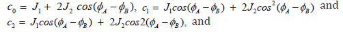

Thus, the number and positions of the peaks in the FMR spectra of these systems are given a quadratic equation in ω or H. The equation will have at most, two meaningful solutions (real and positive ω ). Thus, one expect two peaks in the FMR spectra: a peak corresponding to the acoustic mode where the two magnetizations are precessing in phase; while the second one corresponds to the optical mode for magnetizations precessing out of phase. The peak linewidth and intensity values have also been found [19,89,90].
In the more general case, Eq. (8) should be numerically solved to find the frequencyω as a function of the applied field H and other magnetic parameters of the system (i.e. the resonance condition). Two solutions are found, twoω vs H curves are obtained. The fit of the experimental data to the theoretical curves will easily lead to the values of the magnetic coupling for the case of a trilayer system and to the magnetic coupling and the exchange anisotropy for the spin valve structure. Thus, for intermediate coupling, the biquadratic equation Eq. (8) must be numerically solved. There are, however, some particular cases where analytical formula can be found to describe the system with some interesting equivalences between systems. These cases are discussed below.
Equivalent Systems
In the following situations, analytical relations may exist for the equilibrium relations (Eq. 4a and b) and the equation giving the FMR modes, i.e. the dispersion relationsω vs H (Eq. (8)), (contrary to the general case where these Equations have to be numerically solved). These analytical relations give rise to some interesting equivalences between systems. Note also, that these equivalent systems are inferred, here, from the FMR technique described above, however they could be deduced from torque or magnetization curves.
Uncoupled Layers
When the layers are not coupled, then one may find the resonance
condition by putting J1 = J2 = 0; i.e. cj = 0 in Eq. (8) which
will reduce to 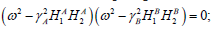 upon substituting the
 by their expressions (Eqs. 9 a-d), one obtains the following two
uncoupled equations:
by their expressions (Eqs. 9 a-d), one obtains the following two
uncoupled equations:

Eq. (10a) is the resonance condition for a (F/AF) bilayer with in-plane HA and exchange HE anisotropy fields, while Eq. (10b) is the resonance condition for a ferromagnetic thin film with in-plane anisotropy field HB. Hence, for uncoupled layers (J1 = 0, J2 = 0), as expected, the general dispersion relation (ω vs H), Eq. (8) correctly reduces to two independent equations which describe a (F)/(AF) bilayer with exchange anisotropy field HE and a single ferromagnetic thin film.
Weak Magnetic Coupling
For small magnetic coupling, it is found after some calculations that Eq. (8) will lead to the two independent resonance conditions (for H applied along the x-axis, i.e. α =φA =φB =0 ):

Comparing the above relations with Eq.(10a), one may deduce that Eqs. (11a) and (11b) correspond to the resonance condition of two (F/AF) bilayers. The first bilayer (F/AF)1 (Eq. (11a) is characterized by the exchange anisotropy field HE1 and the planar anisotropy field HA1 given, respectively, by

While for the second bilayer (F/AF)2, the exchange anisotropy field HE2 and the planar anisotropy field HB2 will be given, respectively, by

These independent relations show that when the magnetic coupling is low, the whole (F)/(N-M)/(F)/(AF) system behaves as two uncoupled bilayers [(AF)/(F)] with magnetic characteristics different from those of layers A and B. Thus, for weak magnetic coupling, there are analytical formulas for the resonance modes (position, intensities and linewidth) [19,82,89,90] and the spin valve structure [(F)/(N-M)/(F)/(AF)] is equivalent to two uncoupled (AF)/(F) bilayers with different magnetic and exchange anisotropy fields, as illustrated in Figure 8. It is found that the bilinear coupling J1 contributes (or modifies) to the exchange anisotropy, while the biquadratic coupling J2contributes to the magnetocrystalline anisotropies (uniaxial and in-plane).
Recall that, the equivalence between the biquadratic coupling and the deviation of the in-plane anisotropy axis was demonstrated [36]. Also the equivalence between the biquadratic coupling and the angular variation of the magnetic coupling was reported [7]. Here, one can see also the equivalence between the bilinear coupling and the exchange anisotropy field in some particular case.

Strong Magnetic Coupling
For strong magnetic coupling, it can be shown that Eq. (8) will give a single solution, valid for the ferromagnetic and antiferromagnetic coupling with different magnetic parameters. This solution, the resonance condition, can be put in the following form:


Once again, when comparing Eq. (14) with Eq. (10a), one infers that Eq. (14) is the resonance condition for a (F)/(AF) bilayer thin film with equivalent magnetogyric ratio, exchange and anisotropy fields given by Eqs. (15a) to (15d). The + and – signs correspond to the ferromagnetic and antiferromagnetic coupling respectively. The whole [(F)/(N-M)/(F)/(AF)] structure behaves as a single ferromagnetic film exchange coupled to an antiferromagnetic layer (F/AF)st.
Hence, for a strong magnetic coupling, the resonance condition is given by an analytical formula, and the spin valve system is equivalent to a single (AF)/(F) bilayer (Figure 9) whose characteristics (equivalent exchange, uniaxial and planar anisotropy fields) are given as a function of the individual layer parameters [4-12, 19]. It is interesting to note that the magnetic parameters of the resulting (F/AF)st can be tuned to convenient values by the choice of the parameters of the initial films, mainly the magnetization and the thicknesses of the ferromagnetic films. Note also that this equivalence between the spin valve system and the (F/AF) bilayer found from the FMR study has also been derived from magnetization curve [69] and from a torque based method [76], different from this analysis.

Conclusion
The present paper focuses on some magnetic phenomena observed in the (F)/(N-M)/(F) trilayer and in the (F)/(N-M)/(F)/ (AF) Magnetic Tunnel Junction (MTJ) or spin valve structure. The magnetic coupling, in (F)/(N-M)/(F), is measured by the bilinear J1 and biquadratic J2 parameters, while the exchange anisotropy at the (F)/(AF) interface is accounted for by the exchange anisotropy field HE. Three experimental methods for the investigation of such structures are described, where the most pertinent relations are given and discussed. In the magnetization curve, the model gives some switching and saturation fields as a function of the magnetic parameters of the structures which may allow the derivation of the intrinsic parameters ((J1, J2 and HE). In the torque curve method, relations giving the torque curve and the slope of the curve may lead to the determination of these intrinsic parameters. The principle of the Ferromagnetic Resonance (FMR) technique is reviewed. In the more general case, the dispersion relation, ω vs H is given by an equation which has to be numerically solved. However, in some particular cases, analytical formula for the resonance condition exist, leading to some interesting equivalences between the initial structure [(F)/N-M/(F)/(AF)] and other simpler systems. For low magnetic coupling, the system [(F)/N-M/(F)/(AF)] behaves as two uncoupled [(AF)/(F)] bilayers with magnetic characteristics different from those of the starting individual layers (A and B). It is found that the effect of the low coupling is to modify the different anisotropies; the bilinear J1 and the biquadratic J2 coupling parameters contribute to, respectively, the exchange and the magnetocrystalline (uniaxial and in-plane) anisotropies. For strong magnetic coupling, the whole system is equivalent to a single (F)/(AF) bilayer thin film. The effective magnetic parameters of the resulting system can be expressed as a function of the magnetic characteristics (magnetization, anisotropy and magnetogyric ratio) of the separate (A) and (B) layers. One may tune the magnetic parameters of the system by the choice of the initial layer characteristics. Note that this equivalence between the spin valve system and the other systems found from the FMR study has also been inferred from other techniques such as the magnetization and the torque curves. Finally, besides the interest in these systems for fundamental research, there is also an interest in the applications, such as the use of the spin valve structure as giant magnetoresistance (GMR) head in magnetic recording.
Acknowledgement
This review is the result of several papers I published in this subject for many years. Also, I had a great pleasure in giving talks on some parts of this topic as an invited speaker/Professor in Universities in Algeria and abroad. I would like to thank the colleagues for the invitations: - From Algeria, Prof. F. Chemam [University of Tebessa (2005, 2013, 2014)], Prof. I.K. Lefkaier, Prof. B. Helifa and Prof. A. Kaouka [Laghouat University and ENS (2014, 2019)]; - From France, Prof. S.M. Chérif [University of Paris 13 (2003, 2005)], Dr J. Ben Youssef [CNRS, UBO, Brest (2005, 2012)] and - From Turkey, Prof. B. Aktas [Gebze Institute of Technology, the Istanbul NMMA-2003]. Finally, in the memory of Prof. J.O. Artman with whom I worked, during the Eighties, at Carnegie Mellon University, Pittsburgh, PA, USA.
Conflict of Interest
None.
References
- P Grünberg (2000) "Layered magnetic structures in research and application" (a review). Acta Mater 48(1): 239-251.
- J C Slonczewski (1995) "Overview of interlayer exchange theory". J Magn Magn Mat 150(1): 13-24.
- M E Filipkowski, C J Gutierrez, J J Krebs, G A Prinz (1993) "Temperature dependence of the 90° coupling in Fe/Al/Fe(001) magnetic trilayers". J Appl Phys 73: 5963-5965.
- B Heinrich, S T Purcell, J R Dutcher, K B Urquhart, J F Cochran, et al. (1988) "Structural and magnetic properties of ultrathin Ni/Fe bilayers grown epitaxially on Ag(001)" Phys Rev B 38(18): 12879-12896.
- A Layadi, J O Artman, RA Hoffman, CL Jensen, DA Saunders, et al. (1990) "Coupling of Ni and NiFe films through an intervening non-magnetic film" J Appl Phys 67(9): 4451-4453.
- A Layadi, J O Artman (1990) "Ferromagnetic resonance in a coupled two-layer system". J Magn Magn Mater 92(1): 143-154.
- B Heinrich, J F Cochran, M Kowalewski, J Kirschner, Z Celinski, et al. (1991) “Magnetic anisotropies and exchange coupling in ultrathin fcc Co(001) structures”. Phys Rev B 44(17): 9348-9361.
- Z Zhang, L Zhou, P E Wigen, K Ounadjela (1994) “Angular dependence of ferromagnetic resonance in exchange-coupled Co/Ru/Co trilayer structures”. Phys Rev B 50(9): 6094-6112.
- A Layadi, J O Artman (1997) "Study of antiferromagnetic coupling by Ferromagnetic Resonance (FMR)". J Magn Magn Mater 176(2-3): 175-182.
- A Layadi, J O Artman (1997) "A ferromagnetic resonance investigation of ferromagnetic coupling". J of Phys D : Appl Phys 30: 3312-3316.
- Rezende, C Chesman, MA Lucena, A Azevedo, FM de Aguir, et al. (1998) "Studies of coupled metallic magnetic thin-film trilayers". J Appl Phys 84: 958.
- B Heinrich, J F Cochran, T Monchesky, R Urban, (1999) "Exchange coupling through spin-density waves in Cr(001) structures: Fe-whisker/Cr/Fe(001) studies". Phys Rev B 59(22): 14520.
- M N Baibich, J M Broto, A Fert, F Nguyen Van Dau, F Petroff, et al. (1988) "Giant Magnetoresistance of (001)Fe/(001)Cr Magnetic Superlattices". Phys Rev Lett 61(21): 2472-2475.
- TL Monchesky, B Heinrich, R Urban, K Myrtle, M Klaua et al. (1999) "Magnetoresistance and magnetic properties of Fe/Cu/Fe/GaAs(100)". Phys Rev B 60(14): 10242.
- S S Parkin (2003) Advanced Research Workshop, Nanostructured Magnetic Materials and their Applications (NMMA). Istanbul pp. 1-4.
- S S P Parkin, K P Roche, M G Samant, P M Rice, R B Beyers, et al. (1999) “Exchange-biased magnetic tunnel junctions and application to nonvolatile magnetic random-access memory (invited)”. J Appl Phys 85: 5828.
- Y Huai, J Zhang, G W Anderson, P Rana, S Funada, et al. (1999) “Spin-valve heads with synthetic antiferromagnet CoFe/Ru/CoFe/IrMn”. J Appl Phys 85: 5528-5530.
- R L Rodrigez-Suarez, S M Rezende, A Azevedo (2005) “Ferromagnetic resonance of the residual coupling in spin-valve systems”. Phys Rev B 71: 224406.
- A Layadi (2005) “Study of the resonance modes of a magnetic tunnel junction-like system”. Phys Rev B 72: 024444.
- J BenYoussef, A Layadi (2010) “Ferromagnetic Resonance Study ofPermalloy/Cu/Co/NiO spin valve system”. J Appl Phys 108: 053913.
- H S Tarazona Coronel, C V Landouro, J Quispe Marcatoma (2014) “Ferromagnetic resonance of spin valves : the case of IrMn(150Å)/Co(50 Å)/Ru(32 Å)/NiFe(50 Å) system”. Revista de Investigation de Fisica 17: 141702101.
- U Rücker, S Demokritov, E Tsymbal, P Grünberg, W Zinn, et al. (1995) "Biquadratic coupling in Fe/Au/Fe trilayers: Experimental evidence for the magnetic‐dipole mechanism". J Appl Phys 78: 387-391.
- M Rührig, R Schäfer, A Hubert, R Mosler, JA Wolf, et al. (1991) "Domain Observations on Fe-Cr-Fe Layered Structures. Evidence for a Biquadratic Coupling Effect". Phys Stat Sol (a) 125(2): 635-656.
- J C Slonczewski (1991) "Fluctuation mechanism for biquadratic exchange coupling in magnetic multilayers". Phys Rev Lett 67(22): 3172-3175.
- A Layadi (2002) "Effect of biquadratic coupling and in-plane anisotropy on the resonance modes of a trilayer system". Phys Rev B 65: 104422.
- A Layadi, JO Artman, BO Hall, RA Hoffman, CL Jensen, et al. (1988) "FMR in evaporated single and multilayer thin Fe films". J Appl Phys 64(10): 5760-5762.
- Q Y Jin, H R Zhai, Y B Xu, Y Zhai, M Lu, et al. (1995) “A study of interlayer coupling in Co/Cu multilayers”. J Appl Phys 77: 3971-3974.
- J Linder, Z Kollonitsch, E Kosubek, M Farle, K Baberschke, et al. (2001) "In situ detection of two ferromagnetic resonance modes in coupled Ni/Cu/Co/Cu(001) trilayer structures". Phys Rev B 63: 094413.
- Yajun Wei, Somnath Jana, Rimantas Brucas, Yevgen Pogoryelov, Mojtaba Ranjbar, et al. (2014) “Magnetic coupling in asymmetric FeCoV/Ru/FeNi trilayers”. J Appl Phys 115: 17D129.
- Yajun Wei, Serkan Akansel, Thomas Thersleff, Ian Harward, Rimantas Brucas, et al. (2015) “Exponentially decaying magnetic coupling in sputtered thin film FeNi/Cu/FeCo trilayers”. Appl Phys Lett 106: 042405.
- K Seemann (2021) "Exchange coupling and natural ferromagnetic resonance phenomena in Fe40Co37Zr11N12/ZrN/Ni80Fe20 film systems with in-plane uniaxial anisotropy". J Magn Magn Mat 529: 167850.
- Salih Çölmekçi, Ali Karpuz, Hakan Köçkar (2021) "Magnetic properties affected by structural properties of sputtered Ni/Cu multilayer films with different thicknesses of Ni layers". Korean J Chem Eng 38(2): 1-6.
- Pius Suh, Pawan Tyagi (2024) "Photovoltaic effect on silicon–alumina–ferromagnet tunnel junction providing insights about spin-dependent molecular spintronics solar cells". AIP Advances 14: 035032.
- Zengxin Wei, David Navas, Sergey A Bunyaev, Marian Abellan, Carlos Garcia, et al. (2024) "Static and dynamical behaviour of magnetically coupled Co/Cu/ CoFeB trilayers". J Magn Magn Mat 589: 171584.
- A Layadi (1998) "Ferromagnetic resonance modes in coupled layers with cubic magneto-crystalline anisotropy". J Appl Phys 83: 3738-3743.
- A Layadi (2003) "Study of the resonance modes in coupled ferromagnetic layers: Effect of the in-plane anisotropy axis directions". J Magn Magn Mat 266(3): 282-289.
- H J Elmers, G Liu, H Fritzsche, U Gradmann (1995) "Indirect exchange coupling for orthogonal anisotropies". Phys Rev B 52(2): R696-R699.
- A Layadi (2004) "A theoretical study of the resonance modes of coupled thin films in the rigid layer model". Phys Rev B 69: 144431.
- Chunmei Wang, Shouheng Zhang, Yicong Huang, Tao Sang, Derang Cao, et al. (2021) "Dynamic interlayer exchange coupling in magnetic anisotropic FeCoB/Ru/FeCoB sandwich trilayers". J Magn and Magn Mat 527: 167801.
- Duo Liu, Shouheng Zhang, Shandong Li (2022) "Interlayer coupling and high frequency performance in magnetic anisotropic FeCoB/Hf/FeCoB trilayers with various Hf thicknesses". Magnetochemistry 8: 65.
- A Layadi (2001) "Ferromagnetic resonance modes in single and coupled layers with oblique anisotropy axis". Phys Rev B 63: 174410.
- Peng-Bin He, Zai-Dong Li, An-Lian Pan, Qiang Wan, Qing-Lin Zhang, et al. (2008) “Theory of ferromagnetic resonance in magnetic trilayers with a tilted spin polarizer”. Phys Rev B 78: 054420.
- A Layadi (1999) A theoretical investigation of the effect of the oblique anisotropy axis on the ferromagnetic resonance linewidth. J Appl Phys pp. 1625-1629.
- W H Meiklejohn, C P Bean (1956) "New magnetic anisotropy". Phys Rev 102: 1413.
- W C Cain, W H Meiklejohn, M H Kryder (1987) "Effects of temperature on exchange coupled alloys of Ni80Fe20‐FeMn, Ni80Fe20‐αFe2O3, and Ni80Fe20‐TbCo". J Appl Phys 61: 4170-4172.
- A Layadi, JW Lee, J O Artman (1988) "FMR and TEM studies of annealed and magnetically annealed thin bilayer films". J Appl Phys 64: 6101-6103.
- Y Ijiri, J A Borchers, R W Erwin, S H Lee, P J Van der Zaag, et al. (1998) "Perpendicular Coupling in Exchange- Biased Fe3O4/CoO Superlattices". Phys Rev Lett 80: 608.
- N J Gökemeijer, R L Penn, D R Veblen, C L Chien (2001) "Exchange coupling in epitaxial CoO/NiFe bilayers with compensated and uncompensated interfacial spin structures". Phys Rev B 63: 174422.
- S M Rezende, A Azevedo, M A Lucena, F M de Aguiar (2001) "Anomalous spin-wave damping in exchange-biased films". Phys Rev B 63: 214418.
- Z Wang, Z Zhou, W Cheng, D Jiang, Q Zhan, et al. (2020) "Surface morphology and exchange bias of wrinkled NiFe/IrMn bilayers grown on polydimethylsiloxane". J Magn Magn Mater 513: 167126.
- A Layadi (2024) "Review of the Exchange Anisotropy and the Methods of Investigation". Mod Concept Material Sci 6(1): 1.
- W C Cain, J W Lee, PV Koeppe, MH Kryder (1988) "Exchange coupled NiFe-TbCo thin films for use in self-biased magnetoresistive heads". IEEE Transactions on Magnetics 24(6): 2609.
- B Heinrich (2000) "Magnetic nanostructures. From physical principles to spintronics". Can J Phys 78: 161.
- M Heigl, C Vogler, A O Mandru, X Zhao, HJ Hug, et al. (2020) "Microscopic Origin of Magnetization Reversal in Nanoscale Exchange-Coupled Ferri/Ferromagnetic Bilayers: Implications for High Energy Density Permanent Magnets and Spintronic Devices". ACS Appl Nano Mater 3(9): 9218-9225.
- A Layadi, WC Cain, J W Lee, JO Artman (1987) "Investigation of Anisotropy by Ferromagnetic Resonance (FMR) in Exchange-Coupled Bilayer Films". IEEE Transactions on Magnetics 23(5): 2993-2995.
- A Layadi, J W Lee, J O Artman (1988) "Spin wave FMR in annealed NiFe/FeMn thin films". J Appl Phys 63: 3808-3810.
- V Ström, B J Jönsson, K V Rao, D Dahlberg (1997) "Determination of exchange anisotropy by means of ac susceptometry in Co/CoO bilayers". J Appl Phys 81: 5003-5005.
- R D McMichael, M D Stiles, P J Chen, W F Egelhoff (1998) "Ferromagnetic resonance studies of NiO-coupled thin films of Ni80Fe20". Phys Rev B 58: 8605.
- C Mathieu, M Bauer, B Hillebrands, J Fassbender, G Güntherodt, et al. (1998) "Brillouin light scattering investigations of exchange biased (110)-oriented NiFe/FeMn bilayers". J Appl Phys 83: 2863-2865.
- A Layadi (2000) "A method for the determination of exchange and magnetocrystalline anisotropies in exchange coupled thin films". J Magn Magn Mater 219(3): 294-302.
- M Tsunoda, Y Tsuchiya, T Hashimoto, M Takahashi (2000) "Magnetic anisotropy and rotational hysteresis loss in exchange coupled Ni–Fe/Mn–Ir films". J Appl Phys 87: 4375-4388.
- A Layadi (2000) "Resonance modes of cubic single crystal thin film with exchange anisotropy : A theoretical study". J Appl Phys 87: 1429-1434.
- H Xi, K R Mountfield, R M White (2000) "Ferromagnetic resonance studies of exchange biasing in Ni81Fe19/Pt10Mn90 bilayers". J Appl Phys 87: 4367-4374.
- A Layadi (2012) Exchange coupled bilayer thin films with tilted out-of-plane anisotropy easy axis. J Appl Phys 112: 073901.
- Jing-guo Hu, Guo-jun Jin, Yu-quiang Ma (2002) “Ferromagnetic resonance and exchange anisotropy in ferromagnetic/antiferromagnetic bilayers”. J Appl Phys 91: 2180-2185.
- A Layadi (2002) "Exchange anisotropy: A ferromagnetic resonance study". Phys Rev B 66: 184423.
- S Mamica, H Puszkarski (2003) "Theory of SWR critical angle effect in Ferromagnetic exchange-coupled bilayer film". Acta Phys Supersficium 5: 5.
- D Spenato, SP Pogossian (2005) "Hysteretic resonance frequencies and magnetization reversal in exchange biased polycrystalline F/AF bilayers". J Magn Magn Mater 285(1-2): 79-87.
- A Layadi (2006) "Analytical expressions for the magnetization curves of a magnetic tunnel junction-like system". J Appl Phys 100: 083904.
- W Alayo, YT Xing, E Baggio-Saitovitch (2009) "Study of spin valve structures with weak and strong interlayer coupling". 11th International Conference on Advanced Materials (ICAM), Rio de Janeiro Brazil.
- W Alayo, Y T Xing, E Baggio-Saitovitch (2009) "Magnetization studies in IrMn/Co/Ru/NiFe spin valves with weak interlayer coupling". J Appl Phys 106: 113903.
- A Layadi, FW Ciarallo, JO Artman (1987) "Torque, FMR and Domain Mode FMR Relations in Thin 'Oblique Anisotropy Axis' Films ". IEEE Trans Magn 23(5): 3642-3644.
- J O Artman (1985) "Determination of anisotropy parameters in magnetically uniaxial specimens by torque derivatives". IEEE Trans Magn 21(3): 1271-1273.
- A Layadi (2001) Investigation of off-aligned exchange coupling by torque curve and ferromagnetic resonance. J Appl Phys 90: 4651-4656.
- A Layadi (1999) "Determination of the magnetic coupling from torque curve". J Magn Magn Mater 192: 353-362.
- A Layadi (2009) “A theoretical study of the torque curves in some magnetic multilayer systems”. Phys Rev B 79: 104434.
- B Heinrich, JF Cochran (1993) "Ultrathin metallic magnetic films: magnetic anisotropies and exchange interactions". Adv Phys 42: 523.
- B Heinrich (1994) "Radio frequency techniques", In Ultrathin magnetic structures II. Edited by B. Heinrich and J.A.C. Bland, Springer-Verlag, Berlin.
- A Layadi (2004) "Investigation of magnetic coupling by Ferromagnetic Resonance",in Nanostructured Magnetic Materials and their applications, edited by B. Aktas, L. Tagirov and F. Mikailov, Kluwer Academic Press 143: 171.
- J Geshev, L G. Pereira, J E Schmidt (2002) “Dependence of the ferromagnetic resonance modes on the coupling strength in exchange-coupled trilayer structures”. Physica B 320(1-4): 169-171.
- W Alayo, MA Sousa, F Pelegrini, E Baggio-Saitovitch (2011) "Analysis of the weak coupling of the IrMn/Co/Ru/NiFe structures by ferromagnetic resonance". J Appl Phys 109: 083917.
- A Layadi (2016) "Resonant and switching fields for a weakly coupled magnetic tunnel junction system". SPIN 6(4): 1640011.
- K V Kulikov, D V Anghel, M Nashaat, M Dolineanu, M Sameh, et al. (2024) "Resonance phenomena in a nanomagnet coupled to a Josephson junction under external periodic drive". Phys Rev B 109: 014429.
- Daniel Markó, Rajgowrav Cheenikundil, Julien Bauer, Kilian Lenz, Wan-Chen Chuang, et al. (2023) "Interpretation of Spin-Wave Modes in Co/Ag Nanodot Arrays Probed by Broadband Ferromagnetic Resonance”. Phys Rev Applied 20: 024059.
- Risto Ojajärvi, F S Bergeret, M A Silaev, Tero T Heikkilä (2022) "Dynamics of Two Ferromagnetic Insulators Coupled by Superconducting Spin Current". Phys Rev Lett 128: 167701.
- J Vogel, W Kuch, J Camarero, K Fukumoto, Y Pennec, et al. (2005) "Interplay between magnetic anisotropy and interlayer coupling in nanosecond magnetization reversal of spin-valve trilayers". Phys Rev B 71: 060404(R).
- A Layadi (2020) Effect of multiaxial stress in thin films on the Ferromagnetic Resonance mode characteristics. J Appl Phys 127: 223907.
- Yaowen Xinga, Zhengren Yana, Jinwu Wei, Caihua Wan, Wenlong Yang, et al. (2021) Ferromagnetic resonance linewidth broadening induced by a tunable inhomogeneity effect. J Magn Magn Mater 517: 167215.
- A Layadi (2015) "A theoretical investigation of Ferromagnetic Resonance Linewidth and damping constants in coupled trilayer and spin valve systems". AIP Advances 5: 057113.
- A Layadi (2018) "Analytical expressions for the Ferromagnetic Resonance mode intensity and linewidths for a weakly coupled magnetic tunnel junction system". J Appl Phys 124: 143901.
-

This work is licensed under a Creative Commons Attribution-NonCommercial 4.0 International License.


