 Case Report
Electromagnetic Processing for Elaboration of Dissimilar Joints. Case Studies with Aluminum
S Marya, GeM, Ecole Centrale Nantes, 1 Rue de la Noë, 44321 Nantes, Cedex, France.
Received Date: September 17, 2020; Published Date: October 09, 2020
Abstract
Magnetic pulse welding (MPW) has potential applications where fusion welding is problematic, such as in dissimilar joints or where the very part integrity, as in electronic components, is likely to be threatened by hot environments. The paper describes some critical applications such as: joining of similar joints between Al wire to Al plate for electric and hybrid applications, dissimilar joints of Al to Cu for electrical conductors, Al to Steel for vehicles, Manganin to Copper for cryogenic applications and joining flexible printed circuit boards. The inductor design and the part set up for the aforementioned applications are critical for successful implementation of MPW. Generally, an air gap between the driver part and the opposite stationary part is required. This prerequisite becomes penalizing in mass production. To circumvent this, the authors have developed innovative solutions via localized humps in case of sheets. The paper proposes to discuss process highlights and characterization of the joints.
Keywords: Magnetic pulse welding; Applications; Air gap; Similar and dissimilar metal joints; Inductor
Introduction
Welding and joining more conventionally involve atomic scale continuity between parts that is obtained by localized fusion, or diffusion combined with or without plastic deformation. Temperature is thus an important physical parameter that combined with time determines the extent of atomic scale mixing. In homogeneous assemblies, the extent of interpenetration between parts does not have important implications other than grain size, phase transformations and overall deformation. However, in heterogeneous assemblies, particularly when the interpenetration is not immune to the formation of intermetallic compounds, temperature –time must become primordial to limit the extent of intermetallic [1]. In other critical assemblies such as wire to plates in electronic components, temperature must remain localized at the junction point such that surrounding elements do not undergo thermal damage [2]. In short for heterogeneous joints or joints with different thermal capacities, solid state welding turns to be the best option. Frictional processes (Linear, Orbital, Stir...), brazing/soldering, explosive and magnetic pulse welding are then the evident options [3]. The choice that is intended in this paper is oriented towards the exploration of the magnetic pulse welding. After a brief description of the process, some case studies will be presented.
Magnetic Pulse Welding
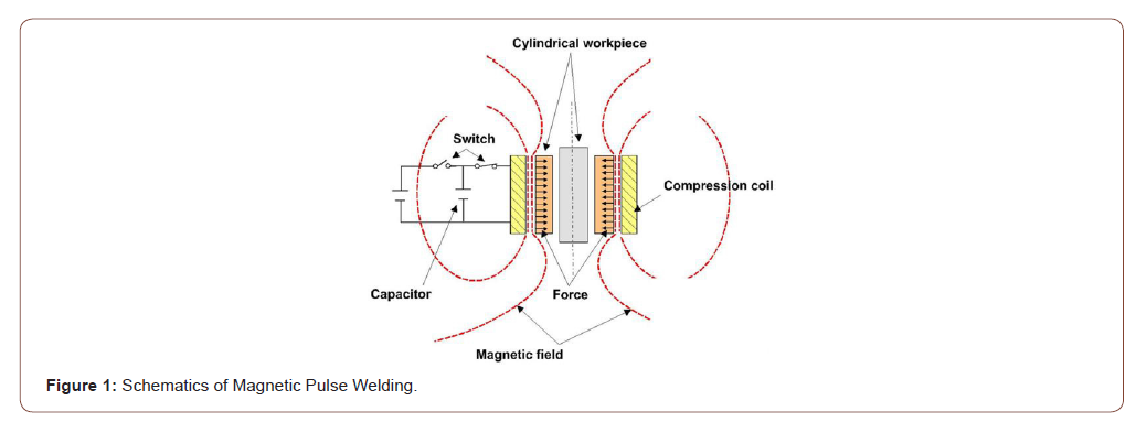
The principle underlying magnetic pulse welding is the impact of one part with another in a way analog to explosive welding, except that the impact energy is imparted by high transient magnetic fields via a rigidly fixed solenoid coil placed close to the flying part as schematically depicted in Figure 1. First, the circuit is charged by accumulating a large amount of electrical energy in a capacitor bank and then rapidly discharged in a solenoid or inductor. The conductive part adjacent to the solenoid is subjected to a changing magnetic field and becomes bestowed with skin currents that in return generate its own magnetic field. The resulting Lorentz forces accelerate the immediate part so as to explosively impact the second stationary part that is rigidly fixed [4-10]. A joint similar to one observed in explosive welding between the two parts is then produced, when two additional conditions are satisfied namely:
1. Impact energy is enough to create short but intense heat at impact point, which implies that an air gap between the flyer and the fixed part is installed for acceleration to take place. The velocity (V) when the flyer part impacts the stationary part depends on the magnetic pressure, the mass of the accelerated part, its material properties and the initial gap between the two parts. For successful welding, roughly the following impact velocity criterions are required [4]:

where HV is the material hardness; ρ the density and dσ/dε is the strain hardening coefficient of the material. This implies that the outer material should be light, its hardness low and should be very good conductor. Subsequently in Al-Cu, Al-Steel, Al-Mg joints, Aluminum reported later on, Aluminum would be the outer part in spite of the fact that copper is a better conductor but heavier than Aluminum.
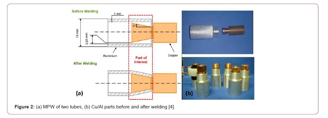
2. The collision takes at such an angle that the oxides are washed away by the air jet, providing thereby clean surfaces for diffusional contact. The minimum contact angle decreases with increasing velocity and density of the flyer material (Figure 2).

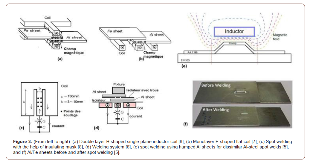
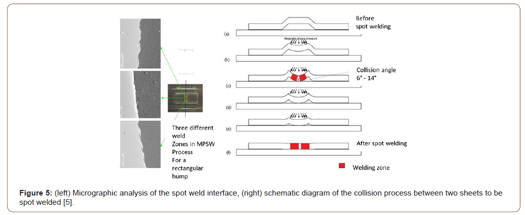
The above-mentioned conditions are met by appropriate part arrangement and induction coils (Figure 2&3) that have been proposed earlier by the authors. In all cases, it’s important to provide a relatively small air gap and conditionally it becomes a handicap in real industrial production. Very recently A.P. Manogaran et al.[5] advanced and implemented the idea of using localized stamped humps such that outside the humps, the parts, mostly sheets, can be rapidly fixed as outside the humps, the sheets are in contact (Figure 3f). Only at humps, the parts are apart so as to provide air gap for acceleration. However, this works for sheets and can be implemented in mass production industry such as automotive sector. This process is designated as magnetic pulse spot welding and described later on in this paper.
Case Studies
Dissimilar joints of Al-Cu tubes
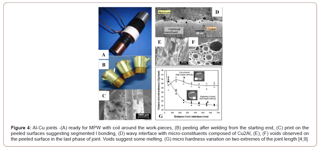
Figure 4 presents some important sequences and observation before and after the pulse welding operations. After welding, it’s easy to peel off aluminum from the copper from the early sections of the joints, i.e. the locations of the first impact on the conical copper tube where acceleration for required impact velocity is still insufficient (Figure 4B). In this part, only traces of aluminum are seen on the peeled copper tube. Progressively towards the mid length of the joint, intermetallics with wavy interfacial pockets are observed by metallographic observations on etched sections (Figure 4D). Peeling from the terminal end is comparatively harder and observation of the peels shows spherical voids that seem to result from local melting subsequent to high impact energy. During impact, aluminum undergoes deformations and its total elongation can be as high as 25 to 30%. There is an effective thinning of the outer tube. Micro-hardness tests on the etched sections with micro constituents show HV of 400 that decreases abruptly section before rising again in aluminum. Hardness reduction in the immediate section of micro constituents suggests that the exothermic reaction during the formation of compound softened the material. Further far off on aluminum, the hardness increases due to strain hardening. This hardness behavior is observed only on sections where microconstituents are observed. For instance, in the first part where impact did not yield only segmented or partial bonding, hardness decreases all the way from the interface to far off locations on aluminum.
Dissimilar Al-Steel spot welds
The stringent requirement of an air gap or standoff distance between parts to be welded remains impractical in production, though not impossible. This constraint can be eliminated by stamping one of the sheets so as to create a natural gap via hump as shown in Figure 3e and 3f. The inductor is designed in such a way that it is placed just above the hump. When the current is discharged, according to the MPW principle, the hump deforms and impacts on to the other material at a very high velocity to realize spot welding. AP Manogaran et al. [5] have successfully tested an optimized stamp shape that generates resistant spot welds. The geometry of the hump determines the size of the spot weld. Tensile shear tests reveal tearing of 0.5 mm thick aluminum sheet around the spot weld made on 1.5 mm plain carbon steel. As suggested and established by metallographic observations of the etched cross sections of spot welds, the central part of the rectangular spot is un-welded (plain interface) and the opposite sides show packets of waves progressing in opposite directions (Figure 5). Since, the process is rapid, only very thin intermetallic layers (2-5μm) are formed and that too only around those wavy regions.
The paper has shortly reviewed some critical applications of magnetic pulse welding that have been previously reported by the authors. The critical process points as inductor design, work piece set up, fixtures and generator characteristics such as discharge energy and time determine the outcome of welds. Interfacial structures are analogous to those seen on explosively welded specimens. Dissimilar joints between Al-Cu, Al-Steel show some intermetallics. The welds tested in tensile and or tensile shear are fractured outside the weld zone.
Acknowledgement
None.
Conflict of Interest
No conflict of interest.
References
- PB Prangnell, YC Chen, A Panteli, F Haddadi (2011) Proceedings of the 7th International conference on processing and manufacturing of advanced materials. THERMEC, Las Vegas, USA.
- R Hultgren (1973) Selected Values of the Thermodynamic Properties of Binary Alloys. American Society for Metals, p. 1435.
- S Marya (2006) International Journal of Mechanical Engineering & Materials 1(1): 1-10.
- S Marya, G Racineux, M Marya, F Gratecap (2007) Proceedings of the 2nd International symposium on smart processing technology.
- AP Manogaran, P Manoharan, D Priem, S Marya, G Racineux (2013) Proceedings of the 8th International conference on processing and manufacturing of advanced materials, THERMEC, Las Vegas, USA.
- T Aizawa (2004) Methods for electromagnetic pressure seam welding of Al/Fe sheets. Welding International 18(11): 868-872.
- T Aizawa, M Kashani, K Okagawa (2007) Application of Magnetic Pulse Welding for Aluminum Alloys and SPCC Steel Sheet Joints. Welding Journal 86: 119-124.
- T Aizawa, K Okagawa, M Kashani (2008) Joining Method through Holes between Insulated Conductors by Applying Magnetic Pressure. IEICE technical report 107(457): 13-16.
- M Marya, S Marya (2004) Interfacial microstructures and temperatures in aluminium–copper electromagnetic pulse welds. Science and Technology of Welding and Joining 9(6): 541-547.
- C Khalil, S Marya G Racineux (2020) Magnetic Pulse Welding and Spot Welding with Improved Coil Efficiency - Application for Dissimilar Welding of Automotive Metal Alloys. J Manuf Mater Process 4(3): 1-20.
-
S Marya, G Racineux. Electromagnetic Processing for Elaboration of Dissimilar Joints. Case Studies with Aluminum. Mod Concept Material Sci. 3(3): 2020. MCMS. MS.ID.000564.
-
Magnetic pulse welding, Applications, Air gap, Similar and dissimilar metal joints, Inductor, Aluminum, Energy, Magnetic field, Material, Temperature
-

This work is licensed under a Creative Commons Attribution-NonCommercial 4.0 International License.


