 Research Article
Effects of Carbon Nanotubes on the Bonding Behavior of Cold Roll Bonded Cu Strips
Bahram Rahnama Falavarjani and Mohammad Reza Toroghinejad*
Department of Materials Engineering, Isfahan University of Technology, Iran
Mohammad Reza Toroghinejad, Department of Materials Engineering, Isfahan University of Technology, Isfahan 84156-83111, Iran.
Received Date: September 06, 2021; Published Date: October 20, 2021
Abstract
A growing interest is being shown to carbon nanotubes (CNTs) due to their excellent mechanical properties as an ideal reinforcement for metal matrixes. In this study, the cold roll boding (CRB) process was used to fabricate Cu/CNT composite strips. For this purpose, the CNTs were dispersed homogeneously between two pure copper sheets which were subsequently roll bonded at room temperature. In order to evaluate the behavior of CNT particles between the Cu strips, optical microscopy, scanning electron microscopy, and energy dispersive X-ray spectroscopy were used along with the peeling test. The microstructure of the Cu/CNT composite consists of two regions: composite regions in which most CNTs are distributed, and CNT-free regions. The results of the peeling test revealed that, compared to roll-bonded Cu strips without particles, the presence of even a small amount of CNTs at the interface could reduce significantly the peeling force for identical thickness reductions. It was also found that threshold thickness reduction decreased but the bond strength of the Cu/CNT interface increased with increasing volume fraction of CNTs.
Keywords: Metal matrix composites (MMC); Cold roll bonding; Bond strength; Copper; Carbon nanotube
Introduction
The idea of composite materials emerged from the need for lightweight materials with improved mechanical and physical properties such as enhanced strength, toughness, and thermal and electrical conductivity. However, extensive application of such materials depends on the selection of proper reinforcement materials [1,2].
Ever since they were discovered by Iijima [3], multiwall carbon nanotubes (MWCNTs) have received increasing attention as a new kind of reinforcement material for the production of advanced engineering composites. Especially advantaged for their low density, carbon nanotubes are also expected to bring about improvements in the mechanical and physical performance of monolithic materials due to their extraordinary properties like ultra-high elastic modulus (about 1 Tpa), tensile strength (150 GPa), and thermal conductivity (about 3000 W/mK) [1,4]. As a result, a variety of fabrication methods have been used over the last two decades to incorporate CNTs in metal matrixes in order to produce carbon nanotube reinforced metal matrix (MM-CNT) composites. The most important challenge in the field of MM-CNT composites as reported by many researchers is the uniform dispersion of CNTs to overcome the inferior mechanical properties mainly caused by the agglomeration of CNTs and the low relative density of the composite [5-7].
Cold pressure welding by rolling, or cold roll bonding (CRB), is a solid-state welding process in which multiple layers of metals are stacked together and rolled to produce adequate deformation that will yield solid-state welds at room temperature [8]. In this process, two or more sheets, plates, or strips of metals or alloys of metals stacked together are passed through a pair of rolls until an appropriate deformation is achieved to produce the solid-state bonding between the original individual metal pieces. The bonding process is, however, hindered by the low mobility of atoms, which may be overcome by the high compressive and shear stresses at the contact surfaces during plastic deformation. Before roll bonding, it is necessary to remove contaminated layers from the surfaces of the metals to be bonded [9-11].
Compared to other methods, CRB is not only inexpensive but also simple so that it can be easily automated for large scale sheets [8]. CRB has been used to join different similar and dissimilar metals such as Al/Al [12], Cu/Cu [13], Al/Cu [14], and Al/Zn [15]. Moreover, the process has been used to disperse ceramic particles into metal matrixes to produce composite sheets like Al/Al2O3 [16,17], Al/TiO2 [18], and Al/TiH2 [19]. Four theories have been proposed to explain the mechanisms involved in the CRB process: the diffusion bonding theory [20], the recrystallization theory [21], the film theory [9-11], and the energy barrier theory [11,22,23]. The energy barrier theory states that no weld will result even if clean surfaces are brought into contact with each other. According to this theory, an energy barrier must be surmounted before bonding can take place. This energy comprises the one required for the rearrangement of surface atoms to achieve a proper bonding configuration, the energy to disperse any surface contaminant layers, and the activation energy required for the atom-to-atom bond formation.
Recent extensions of the CRB and other roll bonding processes, such as the accumulative roll bonding (ARB) and the continual annealing and roll bonding (CAR) processes, used in manufacturing composites encouraged the present authors to use them for producing a Cu-CNT composite. The key issue in the roll bonding process is the establishment of an appropriate bonding between the strips. Hence, it is the aim of the present study to investigate the behavior of CNTs at the interface. For this purpose, the microstructure and the bond strength of two-layered Cu strips and Cu/CNT/ Cu laminations will be evaluated from three different aspects in an attempt to gain a better understanding of the likely effects of CNTs.
Experimental procedures
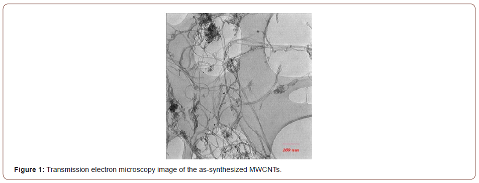
Commercially pure Cu sheets (1 mm in thickness) and MWCNTs (approximately 10-40 nm in diameter and 10 μm in length, supplied by the research institute of Petroleum Industry of Teheran) were used. Figure 1&2 show the transmission electron microscopy (TEM) and scanning electron microscopy (SEM) images of the as-synthesized MWCNTs. The Cu sheet was cut into strips, 100×10×1 mm in dimensions, parallel to the sheet rolling direction. The strips were subsequently annealed at 480 °C for 120 min before they were air cooled to room temperature. The CNTs were purified in a mixture of nitric acid : sulfuric acid (1:3) via ultrasonic cleaning, filtered, washed with deionized water, and finally dried at 120 °C to reduce their impurities.

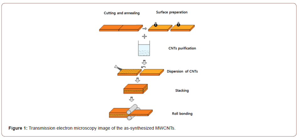
In order to obtain an acceptable metallurgical bond by the CRB process, it is essential to remove any contaminants and oxide layers on the surface of the strips to be joined. The best method reported in the literature for surface preparation is degreasing followed by scratch brushing [10,22]. Using this method in this study, the Cu strips were degreased in an acetone bath before each side of the strips was scratch brushed using a stainless steel circumferential brush (90 mm in brush radius and 0.25 mm in wire diameter). Thus, the initial surface roughness of the samples increased from 0.5 μm to about 4.1 and 4.6 μm in the longitudinal and transverse rolling directions, respectively. A mechanical dispenser was then used to disperse CNTs uniformly over one of the scratch brushed surfaces. Finally, two strips were stacked over each other and fastened at both ends with steel wires.
The roll bonding process was performed at a rolling speed of 2 mm/min with no lubrication using a laboratory rolling mill with a loading capacity of 20 tons and a roll diameter of 125 mm. The samples were carefully handled to avoid renewed contamination and the time between surface preparation and rolling was kept to less than 120 s in order to minimize the likely reoxidation of the prepared surfaces. A series of samples were roll bonded at different thickness reductions (from 35 to 90%) and CNT contents (between 0 and 2.5 vol.%) to investigate the effects of CNTs. Figure 3 depicts a schematic illustration of the CRB process.
The average peeling force was obtained directly from the peeling test according to ASTM-D1876-01. The T-Peel test was carried out using a Hounsfield H50KS tensile testing unit and the load was applied at a constant crosshead speed of 20 mm/min. Also, the average peel strength (bond strength) was calculated using the following equation:

The fracture surface of the strips after the peeling test as well as the interfacial microstructures and chemical compositions of the roll bonded strips were studied using an optical microscope (OM) and a SEM equipped with an energy dispersive X-ray spectrometer (EDX) system.
Results and Discussion
Bonding mechanism in the presence and absence of CNTs
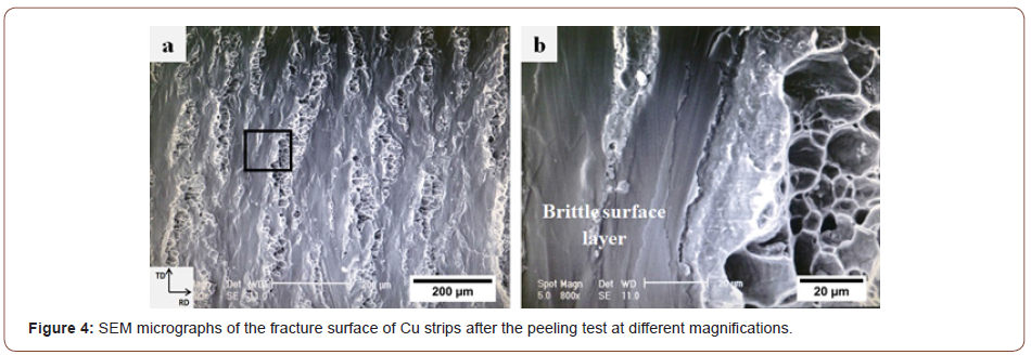
Figure 4 displays a secondary electron (SE)-SEM micrograph of the fracture surface of the Cu strips after delamination at different magnifications. Figure 4a shows a flat matrix with some elongated regions. These regions contain equiaxed dimples as the main characteristic of the fracture surface of ductile metals. Clearly, it indicates the presence of some metallic bonds in these regions.
The brittle surface layer of the strips in roll bonding is the result of both scratch brushing and thin oxide layers formed on the surface. When two stacked strips are subjected to normal pressure to deform them in the rolling direction, they cannot deform in the same way as the underlying ductile metals do; hence, some elongated cracks perpendicular to the rolling direction (RD) are generated in the surface layer of the strips. Consequently, the underlying virgin metals (the metals that are not subjected to the external environment) are extruded through these cracks. Ultimately, the virgin metals join from both sides of the interface to form metallic bonds (Figure 4b). This phenomenon lends good support for the film theory [9-11] because the contact surfaces consist of hard and comparatively brittle layers with a restricted relative movement between them [13].
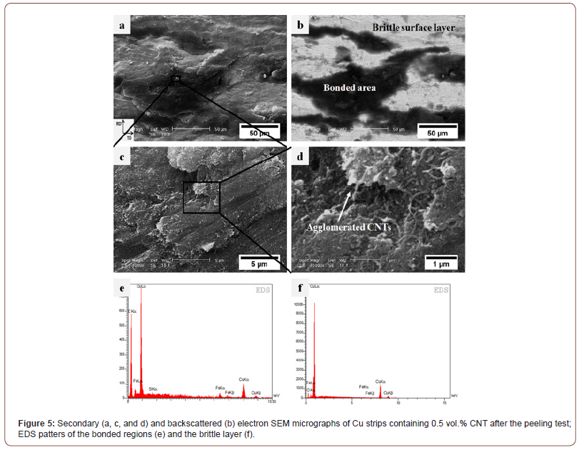
The bonding conditions, however, change when CNTs are introduced between the Cu strips so that the CNTs inhibit direct contact between the strips. In this situation, the cracks lie below the CNT layer and no bond can, therefore, form. Figure 5a and b show the SE-SEM and the backscattered electron (BSE)-SEM micrographs captured from the same location on the peeling surface of Cu strips in the presence of CNTs. Figure 5c and d display the SE images at higher magnifications revealing the role of CNTs on the bonding. The CNTs can be seen in these Figures as well. Instead of the equiaxed dimples in Fig. 4a, the fracture surface in these Figures contains particle-free zones (flat regions) and some composite regions (the Cu atoms into which fragmented CNT layers diffused). These regions are dark in the backscattered image revealing the presence of CNTs. Additionally, the results of the EDS microprobe analyses corroborate the presence of CNTs in these regions.
It may be suggested that the bonding mechanism in the presence of CNT particles takes place in three steps. In the first step, the normal pressure rises slightly and causes the strips to increase in length and the CNT layer to compact until the movement of the particles is restricted; this leads to the fragmentation of the CNT layer into small fragments. Secondly, both the normal rolling tension and the applied compressive force from these fragments cause the brittle surface layer to break down to form some elongated cracks parallel to the rolling direction. Finally, the underlying virgin metals are extruded through these cracks (the metals extrude through the exposed surfaces) and diffuse into the interface and the fragmented CNT layers. Consequently, the strips join as a result of metallic bonds established between the two extruded virgin metals.
It is seen in Figure 5 that CNTs are embedded in the copper matrix but that there are also some CNT clusters. CNTs have a large specific surface area (up to 200 m2/g) and they, therefore, tend to agglomerate to form clusters due to Van der Waals forces [4-6]. This is assisted by the non-wetting nature of the CNTs [4]. The local deformation around these clusters provides the initiation sites necessary for the nucleation of microcracks. Thus, the delamination of strips comprises the nucleation and coalescence of microcracks and the debonding of CNT clusters from the matrix.
Influence of CNTs on threshold thickness reductions
In order to investigate the influence of CNTs on threshold thickness reductions, three groups of samples (i.e., Cu strips without any particles plus those containing 0.25 and 0.5 vol.% CNT) were roll bonded at different thickness reductions. The peeling force of the Cu strips was initially compared with that of strips containing 0.25 vol.% CNT at different thickness reductions to study the effect of CNTs on the threshold thickness reductions. Figure 6 and Figure 7 show the results of the peeling test (peeling force versus peel distance) for the Cu/Cu interfaces lacking CNTs and in the presence of 0.25 vol.% CNT. Based on these Figures, the peeling force largely depends on the amount of thickness reduction in both cases, so that peeling force increases with increasing thickness reduction. The bonding that occurs between the Cu strips is highly dependent on the extent of the underlying metal extrusion when subjected to normal pressure. Therefore, higher thickness reductions lead to enhanced rolling pressure, surface expansion, and area fraction of cracks so that more virgin metal can be extruded through both sides of the interface.
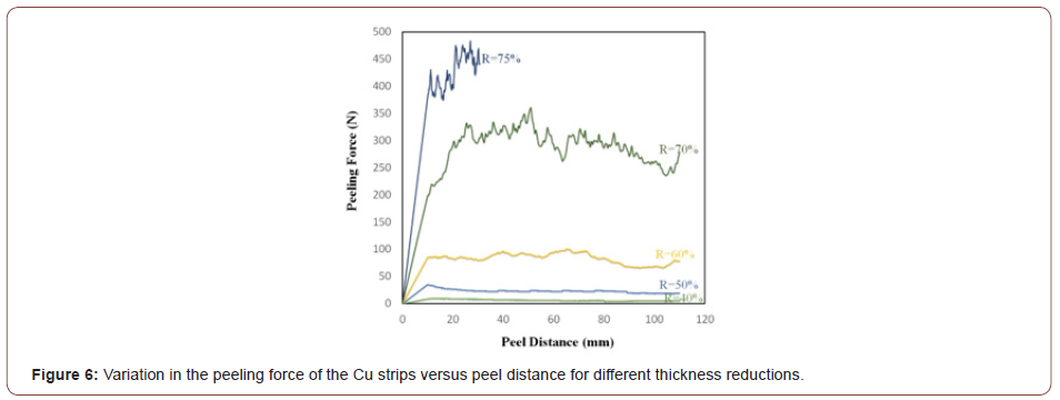
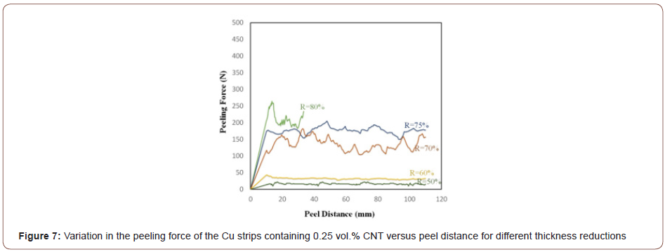
Figure 8 illustrates the optical and SEM micrographs of the peeling surface of the Cu/Cu interface produced by 50% and 70% thickness reductions. The optical micrographs confirm the fracture of the brittle layer and the formation of elongated cracks. Comparison of the OM and SEM micrographs suggests that the dark traces and the light zones in the OM micrograph must represent the bonded regions and the brittle surface layer of the strips, respectively. The amount of virgin metals in contact with each other at the interface is very low because only a few surface cracks can form when the reduction in thickness is small (Fig. 8a and c). Furthermore, the cracks are very shallow and the metallic bonds only form on a thin surface layer so that the strips cannot establish strong joints. Indeed, some of the cracks tend to nucleate during the early stages of deformation due to the lower ductility of the surface layer. As deformation proceeds, however, they propagate along the transverse direction (TD) and new cracks begin to form. Thus, the depth and area fraction of the cracks increase with increasing thickness reductions (Figure 8b and d), leading to more metallic surfaces to be exposed at the interface. Based on an analytical model [24], the location of the bonding point gradually approaches the entrance of the roll gap as thickness reduction increases. This means that the bonding length along the contact boundary of the interface and the corresponding bond strength increase.
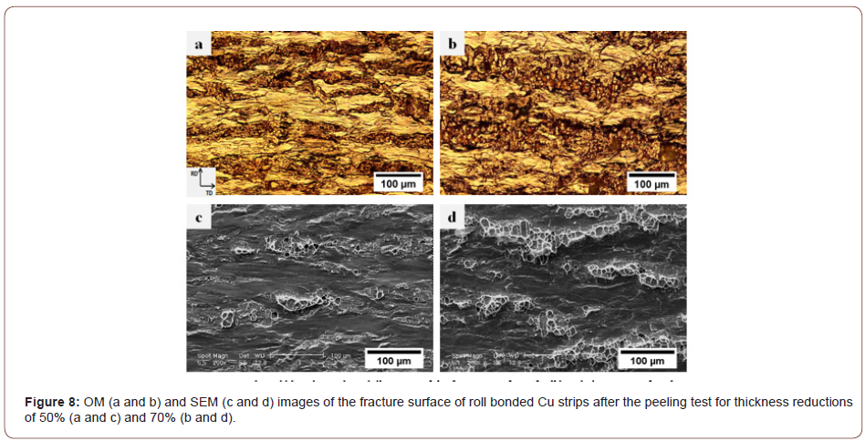
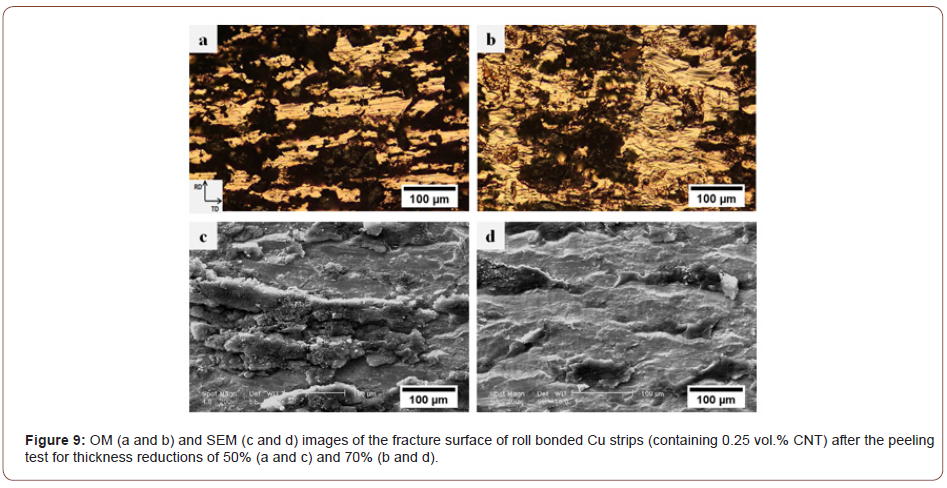
Figure 9 presents the OM and SEM images of the fracture surfaces of the Cu/CNT interface (containing 0.25 vol.% CNT) after the peeling test for thickness reductions of 50% and 70%. Clearly, at low surface expansions (Figure 9a and c), the CNTs remain at the interface, cover the whole surface, and establish a weak bond with the underlying metal. However, an increase in thickness reduction (Figure 9b and d) causes the composite regions to shatter, while the volume of the metals diffusing at the interface and into the bonded area also increases. Thus, the bonding between the CNTs and the underlying metals is improved so that a greater force is required to delaminate the roll bonded composite strips. Lu et al. [25] reported that the nano-sized particles used at the interface play the same role as the second phase in composite materials, inducing the dispersion hardening and leading to dislocations to pile up around the particles. In sum, when the thickness reduction is low, the particles introduced into the composite fail to play the same function as the second phase because they are not embedded in the matrix and establish only weak bonds with the underlying surface.
If the deformation gradually increases, each group will face either of two critical thickness reductions as explained below:
1. Metallic surfaces fail to form strong bonds unless they deform
beyond a critical thickness reduction. This threshold value is
designated by Rt and expressed as the minimum percentage
reduction that consistently results in bonding emerging from
the roll gap [11].
2. When the thickness reduction rises to a certain critical value,
Rf, the bonding becomes so strong that, rather than observing
delamination to occur, the specimens break in the base metal
and the peeling test is stopped. It is indeed at this critical value
that the bond strength of the roll bonded strips reaches the
strength of the base metal.
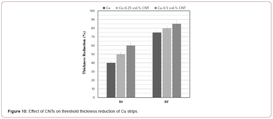
Figure 10 compares the Rt and Rf values of Cu strips lacking CNTs with those containing 0.25% and 0.5 vol.% CNT. Clearly, the degree of threshold deformations depends on the volume fraction of CNTs so that the Rt and Rf values increase as a result of introducing CNTs between the strips. As already mentioned above, bonding occurs when the surfaces of the virgin metals get exposed to each other. This is why any contamination or intervening particles hinder the joining of the strips. As seen in Figure 9, CNTs act as barriers preventing the extruded metals to come into direct contact with each other and, thereby, postpone the occurrence of bonding. In other words, more thickness reduction is required for the metallic atoms to diffuse through the CNTs. This phenomenon may also be explained by reference to the energy barrier theory [11,22,23] to the effect that introducing CNTs between the strips increases the required energy for rearrangement of the surface atoms to achieve a proper bonding configuration, dispersal of any surface contaminant layers and activation energy for atom-to-atom bond formation. More deformation is, therefore, required to overcome the energy barrier.
Effect of CNT quantities on bond strength
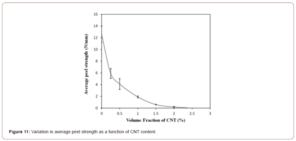
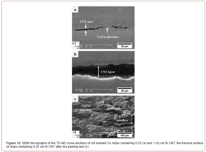
Figure 11 shows the effect of the volume fraction of CNTs on average peeling strength for a constant thickness reduction of 70%. Clearly, the average peel strength of the Cu strips substantially decreased from 12.6 N/mm (in strips without CNTs) to 0.2 N/mm (in those containing 2 vol.% CNT). Practically, the bond strength of the Cu strips containing 2 vol.% CNT was considerably weak, and no bonding occurred between the strips when the CNT content was more than 2 vol.%. Figure 12a and b show the TD-ND cross-sections of the roll bonded Cu strips (for a 70% thickness reduction) containing 0.25 and 1 vol.% CNT, respectively. Obviously, increasing the CNTs particles between the strips led to increased thickness of the CNT layer so that the underlying virgin metals had to be extruded through a longer distance to form metallic bonds. Furthermore, in the samples containing low amounts of CNT (Figure 12a), regions were observed at the contact surface that are not covered by CNTs. This resulted in opposing brittle surface layers to come into direct contact with each other to form a strong Cu/Cu interface. These regions can be seen somewhere in the fracture surface of the specimen containing 0.25 vol.% CNT (Figure 12c).
On the other hand, some researchers maintain that the presence of CNT particles adjacent to the asperities affects the tribological behavior of the surface layer. Actually, these particles serve as a lubricant to reduce the friction coefficient at the interface [17,26]. Tzou et al. [27] reported the bond strength to decrease with declining friction coefficient at the interface. Moreover, CNTs have been generally found to decrease the friction coefficient due to their excellent solid lubrication [7,28]. It may, therefore, be claimed that increasing the volume fraction of CNTs causes the friction between opposing surfaces to dwindle, which gives rise to a rapid decrease in bond strength.
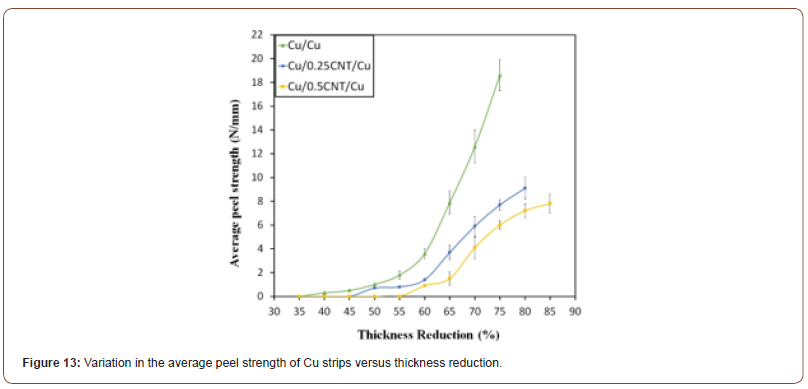
Figure 13 shows average peel strengths of the Cu strips, with and without CNTs, produced with various values of thickness reduction. Clearly, although bonds begin to form at Rt, the bond thus realized is not so strong. In fact, acceptable bonds obtain only when the thickness reduction in the samples containing 0, 0.25 and 0.5 vol.% CNT reach 55%, 60%, and 65%, respectively. Beyond these levels, bond strength increases rapidly. Furthermore, it is obvious that even a small amount of CNT (0.25 vol.%) can lead to a significant decrease in bond strength for a given thickness reduction. As already mentioned, the presence of CNT particles inhibits bonding and the underlying metals will have to diffuse through the CNT particles and clusters in order to form metallic bonds. To obtain a given bond strength, a greater thickness reduction is, therefore, required when the amount of CNT particles between the Cu strips increases. This finding is in good agreement with the observations reported in previous studies [16-19].
Conclusion
In this work, Cu strips with and without CNTs were roll bonded at ambient temperature to investigate the effects of CNTs on the bonding behavior of Cu strips. The conclusions drawn from this study may be summarized as follows:
• The post-delamination fracture surface of Cu strips consists
of some equiaxed dimples as the main characteristic of the
fracture surface of ductile metals. However, when CNTs are
introduced between Cu strips, the delamination comprises
the nucleation and coalescence of microcracks as well as the
debonding of CNT clusters from the matrix.
• The peeling force and average peeling strength of Cu strips
with and without CNTs largely depend on thickness reduction
such that these parameters exhibit increments with increasing
thickness reduction.
• CNTs prevent the bonding of extruded metals; this will require
greater reductions in thickness to allow metallic atoms to diffuse
through the CNTs. Therefore, the threshold thickness reductions
(Rt and Rf) increase as a result of increased volume
fraction of CNTs.
• When the CNT content between the strips increases, the underlying
metals need to be extruded through a longer distance
in order for them to meet, resulting in considerable decreases
in bond strength and average peeling force.
Acknowledgment
None.
Conflict of Interest
No conflict of interest.
References
- Cho S, Kikuchi K, Miyazaki T, Takagi K, Kawasaki A, et al. (2010) Multiwalled carbon nanotubes as a contributing reinforcement phase for the improvement of thermal conductivity in copper matrix composites. Scripta Materialia 63(4): 375-378.
- Nishida Y (2013) Introduction to Metal Matrix Composites: Fabrication and Recycling. Springer Science & Business Media.
- Iijima S (1991) Helical microtubules of graphitic carbon. nature 354(6348): 56-58.
- Agarwal A, Bakshi SR, Lahiri D (2010) Carbon nanotubes: reinforced metal matrix composites. CRC press.
- Kim KT, Cha SI, Hong SH, Hong SH (2006) Microstructures and tensile behavior of carbon nanotube reinforced Cu matrix nanocomposites. Materials Science and Engineering: A 430(1-2): 27-33.
- Lahiri D, Bakshi S, Keshri A, Liu Y, Agarwal A (2009) Dual strengthening mechanisms induced by carbon nanotubes in roll bonded aluminum composites. Materials Science and Engineering: A 523(1-2): 263-270.
- Scharf T, Neira A, Hwang J, Tiley J, Banerjee R (2009) Self-lubricating carbon nanotube reinforced nickel matrix composites. Journal of Applied Physics 106(1): 013508.
- Li L, Nagai K, Yin F (2008) Progress in cold roll bonding of metals. Science and Technology of Advanced Materials 9(2): 023001.
- Bay N (1986) Cold welding. Part 1: characteristics, bonding mechanisms, bond strength. Metal Construction.
- Bay N (1986) cold welding. Part 2: process variants and applications. Metal Construction 18(8): 486-490.
- Cave J (1973) The mechanism of cold pressure welding by rolling. J Inst Met 101(7): 203-207.
- Jamaati R, Toroghinejad MR (2010) Investigation of the parameters of the cold roll bonding (CRB) process. Materials Science and Engineering: A 527(9): 2320-2326.
- Hosseini S, Hosseini M, Manesh HD (2011) Bond strength evaluation of roll bonded bi-layer copper alloy strips in different rolling conditions. Materials & Design 32(1): 76-81.
- Eizadjou M, Talachi AK, Manesh HD, Shahabi HS, Janghorban K (2008) Investigation of structure and mechanical properties of multi-layered Al/Cu composite produced by accumulative roll bonding (ARB) process. Composites Science and Technology 68(9): 2003-2009.
- Abbasi M, Taheri AK, Salehi M (2001) Growth rate of intermetallic compounds in Al/Cu bimetal produced by cold roll welding process. Journal of Alloys and Compounds 319(1-2): 233-241.
- Jamaati R, Toroghinejad MR (2010) Effect of Al2O3 nano-particles on the bond strength in CRB process. Materials Science and Engineering: A 527(18): 4858-4863.
- Rezayat M, Akbarzadeh A (2012) Bonding behavior of Al–Al2O3 laminations during roll bonding process. Materials & Design 36: 874-879.
- Soltani MA, Jamaati R, Toroghinejad MR (2012) The influence of TiO2 nano-particles on bond strength of cold roll bonded aluminum strips. Materials Science and Engineering: A 550: 367-374.
- Alizadeh M, Paydar M (2009) Study on the effect of presence of TiH2 particles on the roll bonding behavior of aluminum alloy strips. Materials & Design 30(1): 82-86.
- Mitani Y, Vargas R, Zavala M (1984) Deformation and diffusion bonding of aluminidecoated steels. Thin solid films 111(1): 37-42.
- Parks JM (1953) Recrystallization welding. Welding J 32(5): 209s-222s.
- Milner D, Vaidyanath L (1960) Significance of surface preparation in cold pressure welding. MET CONSTR BR WELD J 7: 1-6.
- Mohamed H, Washburn J (1975) Mechanism of solid state pressure welding. Welding J 55: 302s-310s.
- Yong J, Dashu P, Dong L, Luoxing L (2000) Analysis of clad sheet bonding by cold rolling. Journal of Materials Processing Technology 105(1): 32-37.
- Lu C, Tieu K, Wexler D (2009) Significant enhancement of bond strength in the accumulative roll bonding process using nano-sized SiO2 Journal of Materials Processing Technology 209(10): 4830-4834.
- Strijbos S (1980) Phenomena at the powder-wall boundary during die compaction of a fine oxide powder. Ceramurgia International 6(4): 119-122.
- Tzou G, Tieu A, Huang M, Lin C, Wu E (2002) Analytical approach to the cold-and-hot bond rolling of sandwich sheet with outer hard and inner soft layers. Journal of Materials Processing Technology 125: 664-669.
- Arai S, Fujimori A, Murai M, Endo M (2008) Excellent solid lubrication of electrodeposited nickel-multiwalled carbon nanotube composite films. Materials Letters 62(20): 3545-3548.
-
Bahram Rahnama Falavarjani, Mohammad Reza Toroghinejad. Effects of Carbon Nanotubes on the Bonding Behavior of Cold Roll Bonded Cu Strips. Mod Concept Material Sci. 4(4): 2021. MCMS. MS.ID.000589. DOI: 10.33552/MCMS.2021.04.000589.
-
Metal matrix composites (MMC), Cold roll bonding, Bond strength, Copper, Carbon nanotube, Bonding behavior, Cu strips, Materials, Metal matrixes, CNT particles, Reinforcement, surface contaminant layers, Electron microscopy
-

This work is licensed under a Creative Commons Attribution-NonCommercial 4.0 International License.


