 Research Article
Investigation of fatigue strength evaluation of welded structure on spirally welded tank wagon via finite element analysis
Gokhan Cil1*, Fatma Mirza2, Yusuf Oranci2, Oguzhan Erdogan2, Okan Unal3,4,5
1Erciyas Steel Pipe Co., Design Center, Duzce, Turkey
2RC Industry R&D Department, Sakarya, Turkey
3Department of Mechanical Engineering, Karabuk University, Karabuk, Turkey
4Modern Surface Engineering Laboratory (MSELAB), Karabuk University, Karabuk, Turkey
5CKN Engineering, Project and Consultancy, Technology Development Zone, Karabuk, Turkey
Gokhan Cil, Erciyas Steel Pipe Co., Design Center, Duzce, Turkey
Received Date:January 29, 2024; Published Date:February 22, 2024
Abstract
Rail systems transportation is developing in a constantly increasing demand due to its safety and capability. Qualified vehicle designs are carried out to improve transportation performance and duration. Design approaches such as increasing the quality of the materials, increasing the performance of critical zones exposing dynamic loading, and reducing the percentage of critical locations in the entire vehicle are constantly developed. In this study, the performance of the spirally welded tank wagon under static and dynamic loading was examined via three-dimensional finite element analysis. It is particularly focused on welded zones causing critical stress and failure under dynamic loading. The differences between the spirally welded and conventional (Zaes) tank wagon produced with different welding connection and geometry approaches were also examined.
Keywords:Tank wagon, fatigue, welded zone, strength, finite element analysis
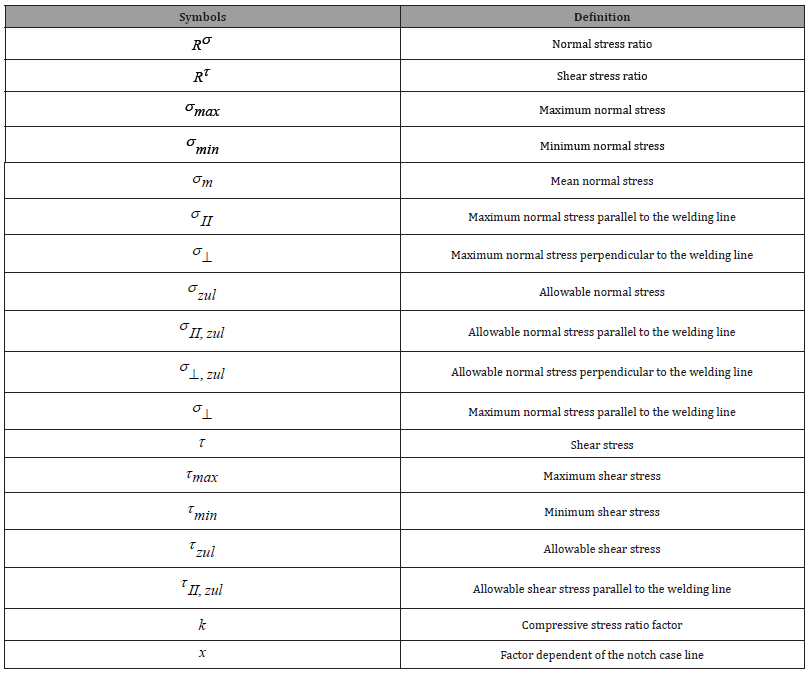
Nomenclature
Table 1:
Introduction
Rail transportation is known as the most reliable transportation among transportation methods [1]. It is widely used in the transportation of passengers, mines and large tonnage systems [2]. Tank wagons are the most widely used railway system vehicles, particularly in hazardous product transportation [3]. It is utilized as the primary choice for the transportation of petroleum and its derivatives. New tank wagon designs are constantly emerging majorly to increase carrying capacities [4]. Reliability, safety and sustainability are the critical features among the most important design criteria [5]. Since such vehicles are intensely exposed to dynamic loads therefore, crack formation, propagation and eventually catastrophic failures should be carefully evaluated [6]. Tank wagons are initially studied in terms of static strength and structural stability. Simultaneously, the fatigue performance of the joining and welded zones is also taken into consideration during the design [7]. The wagon consists of steel components with different geometries welded together. Welded connections are naturally stress-concentration regions [8]. These critical regions have less capability and resistance against fatigue failure. Besides, instantaneous monitoring and observation of crack formation/propagation that cause fatigue failure is not always possible, therefore the failure can occur suddenly, and leads to catastrophic safety problem in the railway industry [9]. Therefore, fatigue strength analysis and evaluation is a decisive part of railway vehicle design, and various technical procedures have been developed in order to minimize failure during operation. Among these, DVS 1612–2014 [10] and UIC B 12/RP 17 [11] are the most widely used procedures in the railway industry in recent years.
Spirally welded pipes, or also known as “HSAW” pipes, have become industrially remarkable for hydrocarbon transport under high pressure [12,13]. Metallurgical structure improvements and mechanical performance enhancement, as well as developments in the production process, have further increased the utilization of such pipes [13]. It is a more economical and effective method in the production of thin-walled and large-diameter pipes. It consists of a hot rolled steel coil and spiral welding. They are made from single and continuous helical welded and wrapped hot rolled steel strip from end to end [14]. Pipe diameters range from approximately 500 to 3000 mm and thicknesses range from 9 to 25 mm [15].
Freight wagons involving welded connections and structures are typically subjected to dynamic loads [16]. For this reason, fatigue failure is inevitably observed as a common type of failure due to the welding zone concerns. The most common technical prescription used to examine fatigue failure and taking necessary precautions at the design stage is the DVS 1612–2014 approach [10]. Evaluation of welded structures in terms of fatigue is carried out by nominal stress method, effective stress method, and multiaxial stress method. The nominal stress method is a widely used method and classifies welded connections according to nominal stress and S-N approach [17]. The failure criterion is based on comparing the nominal stress to the stress value at which fatigue failure occurs.
The advantage of using this method, especially in finite elements, is that the mesh quality is not directly effective. It is related to the nominal stress obtained. This approach is preferred since it is quite difficult to determine the S-N curve, considering the loading types and assembly features of complex parts [18]. It is quite complex to obtain the exact stress in stress concentration regions in finite element analysis. Accuracy may vary depending on the mesh sensitivity, particularly around the weld root and welded zones. In order to eliminate this variability, the Hotspot stress method is used in fatigue analysis [19]. Many studies show that a multi-axial stress distribution occurs in welded zones even under uniaxial loading. An approach is being developed to determine fatigue strength according to multi-axial criteria. Welded zone design standards create different fatigue life evaluation curves, and these curves are obtained in multi-axial loading tests [7,20].
In this paper, the fatigue characteristics of the welded zones of the spiral tank wagon has been analyzed. The loading condition was based on EN 12663-1:2010 Railway Application -- Requirements for Railway Vehicle Body Structure [1]. The fatigue evaluation method is based on the standard of DVS 1612-2014 Design and endurance strength analysis of steel welded joints in rail-vehicle construction [21]. The evaluation of fatigue life was performed by finite element analysis, and particularly the fatigue strength of the critical weld parts investigated. The paper ensures a fundamental reference for the multi-axial stress approach on the fatigue assessment of welded structures in the spiral tank wagon.
Spiral Tank Wagon main structure
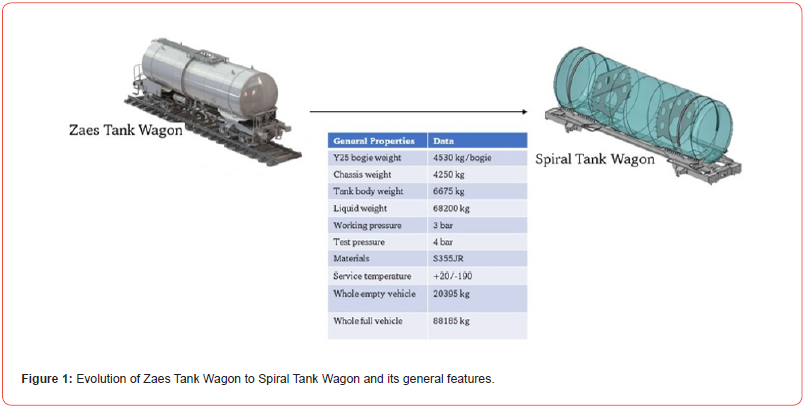
Conventional tank wagon constructions are formed by welding the pipes by joining the ends of cylindrical steel plates through a longitudinal weld [22]. The structure has rounded areas along the longitudinal seams, defects consisting of pits and bumps (corresponding to the joints of tubular sections) and many weakened areas causing deformities in the weld [23]. Spiral tank wagons are intended to be produced by spirally wrapping a strip or steel plate into a tube and a gasket for tankers and similar vehicles to eliminate such weaknesses [24]. In this way, ensuring the specified surface integrity provides the strength improvement and ease of production. In Figure 1, the spiral tank wagon evolved after the Zaes tank wagon, and its general features are shown.
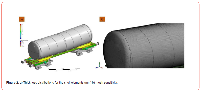
Firstly, a CAD model of the spiral welded tank wagon was created, and the step file was transferred into ANSYS software [25]. A simplification study was performed by removing the details whose effects were neglected in the structural analysis. The model was completed by adding Y25 bogies to the data. The vehicle was modelled with shell elements except for the spiral wagon structure and bogies. Thickness distributions for the shell elements used are shown in Figure 2a. There are 2,612,874 nodes and 1,071,659 elements used in the analysis. The mesh density is shown in Figure 2b. The material used is S355 JR/J2. Elastic modulus of the material is 210 GPa, poison ratio is 0.3 and yield strength is 355 MPa, respectively.
Fatigue Strength Analysis
In line with the content of this study, the German National Welding Standard DVS1612 was used. The standard is preferred by many railway vehicles and welded product manufacturers, as it gives effective results about the reliability of the welds. This approach is based on the standard of Moore-Kommers-Jasper (MKJ) diagrams [26]. A diagram is selected depending on the type of welding structure, the characteristics of the welded zone, the test method, and the type of the load. For fatigue strength examinations, stress components must be calculated in the weld zone. Stress components are calculated in two ways (Figure 3): normal stresses (σ σ ⊥), parallel to the axial force and perpendicular to the welding direction, and shear stress (τ ), occurring parallel to the weld line [27].
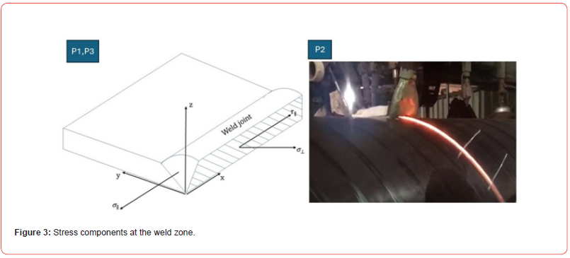
According to the DVS 1612 approach, the maximum allowable stress is defined as a function of the ratio between the maximum stress σmax and the minimum stress σmin . The curves defining allowable stresses, called “notch state lines”, are decomposed into normal, longitudinal and shear stress components (Figure 3) [28].

Allowable tensile and compressive stresses for longitudinal and normal stresses are obtained by using Eq. 2 and Eq. 3, respectively. The compressive stress ratio factor “k” is the opposite of the stress ratio in Eq. 3. Allowable shear stress is also evaluated by means of Eq. 4. “x” and “τ_(zul,R=-1)” are the parameters that change depending on the notch condition and evaluated according to different conditions such as weld joint geometry, weld type and weld performance [29].

Table 1 clarifies the notch states for the DVS approach on the metal. It is clear from the approach that notch state lines for each stress direction follow a decreasing alphabetical order. The notch case line with the highest resistance is “A+” and the lowest resistance is “F3”. The notch line “G+” has the highest acceptable value and “H-” has the lowest for shear stresses. The highest resistance notch case lines are reserved for the base metal and thermally affected areas, regardless of stress direction [29].
Table 2:The notch states for the DVS technical code depending on the metal state [29].

*base metal (B), thermally influenced (T), welded joint (W).
The allowable stress limits focused on in Eq.s 2, 3 and 4 are shown graphically in MKJ diagrams, where the fatigue cycle is associated with the maximum stress. The MKJ diagrams show the safe values for different notch state lines at longitudinal loads. Initially MKJ diagrams are valid for the thickness range from 2 to 10 mm. For thicker plates, fatigue strength gradually decreases [29]. The allowable stress for tensile and compressive stresses should never exceed the yield strength of the material. For shear stresses, the allowable stress should never exceed the yield strength divided by 3 . It should be noted that the allowable limits for compressive stresses are higher [29]. When all stress components are lower than the allowable stress “σzul ”, the fatigue life is considered infinite with a probability of 99.5%. If high levels of stress are observed in more than one component, the fatigue strength is also subjected to the inequality in x in the equations and controlled. When the result in the equations is less than or equal to 1 (Eq. 5 and Eq. 6-determine the usage factor-UF), infinite fatigue life can be achieved within the confidence level determined by DVS 1612 [28, 29].

σ and σzul are the second-order tensors in the global and the local coordinate systems, respectively.
According to EN 12663-1:2010 [1], the fatigue strength of the spiral tank wagon was evaluated based on the multiaxial stress method mentioned above. Different types of fatigue conditions were obtained at optimum acceleration amplitudes. According to the standard of DVS 1612-2014, the fatigue strength of the material in these conditions was determined by ANSYS APDL. In fatigue analysis, the weld positions and local coordinate system were determined initially, then fatigue strength loading conditions were applied, normal and shear stresses were evaluated. Average stress, dynamic stress amplitude, stress ratio and safety stress were calculated by considering discontinuities such as notches in the weld area. MKJ fatigue curve was drawn by calculating the utilization degree in uniaxial and multi-axial loadings [23, 30, 31].
Critical Zones of Fatigue Evaluation
The locations specified according to the DVS1612 standard coded with letters and numbers are the locations marked in different welding joints on the spirally welded tank wagon (Figure 4). The welding design and application comply with the UNE-EN 15085 standard in order to withstand specified allowable stress limits [32]. The MKJ fatigue approach was evaluated at the specified locations, maximum stress, minimum stress, safety coefficient, safe stress and usage factor values were determined [7, 33]. The loads applied to the wagon frame comply with the requirements of the UNE-EN 12663-2 standard, which specifies the loads to be considered in these vehicles. Among all load cases described in this standard, it relates the lateral and vertical inertial accelerations caused by the rail to the wagon during operation. After the model was meshed precisely and the boundary conditions were defined, the solution phase was implemented. Stress tensors calculated in each element of the model were used in post-fatigue analyses. First, the stress results obtained for the face of each element are expressed by the three stress components mentioned in Section 2.1. The maximum and minimum stress values for each stress component will define a fatigue cycle for each member. The stress ratio will then be calculated along with the corresponding maximum acceptable value based on the MKJ diagrams and the corresponding notch state line. A total of four usage factors are obtained on each element side of the model, corresponding to the four relationships presented in Eq. 2. The maximum utilization factor will be considered as the representative factor for comparison purposes as it will determine the fatigue failure [34].
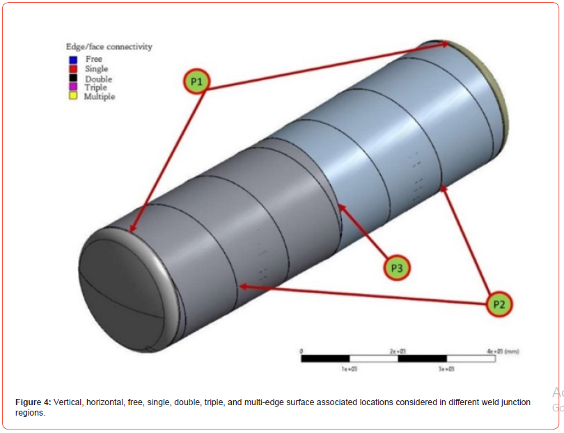
The tank wagon was modeled under different loading conditions using ANSYS software. In the global coordinate system, all normal and shear stresses in the X and Y plane perpendicular to the welding direction were obtained. Figure 5 shows the fatigue performance evaluated at different locations [15].
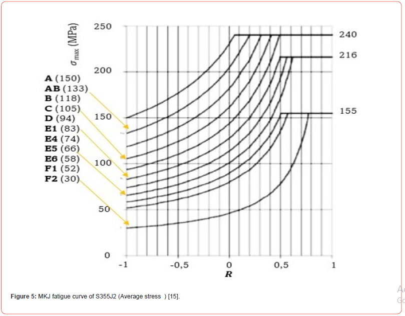
Table 2 shows the maximum stress, minimum stress, safety coefficient, safe stress, and stress factor values after fatigue analysis in different regions in Figure 5. Maximum and minimum normal stresses are obtained by plane stress and safe stress values. Due to the limited volume of the report, only data for the first three nodes with insufficient dynamics are shown. Analysis of the results revealed that all nodes located in the weld zone showed sufficient dynamic strength according to Eq. 6. It has been observed that all safety coefficients in the determined nodes are greater than one [35]. Analysis of theoretical data shows that there are no nodes with insufficient dynamic strength [26].
Table 3:Fatigue strength of welded zone obtained in different welding regions of the tank.

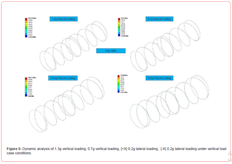
Figure 6 shows the dynamic analysis results under vertical load condition conditions with 1.3g vertical loading, 0.7g vertical loading, [+X] 0.2g lateral loading, and [-X] 0.2g lateral loading. According to the analysis results, the maximum stresses obtained in the wagon were below the allowable stress. Vertical irregularities in the behavior of wagons and the profile of the road cause instability of the vehicle body [36, 37]. In the studies conducted, all modal frequencies applied above the critical frequency vibration values indicate lateral displacement, thus showing the importance of considering the rolling motion for the freight wagon. Road irregularities are vital and can cause products carried in freight vehicles to overturn [38, 39]. Therefore, the dynamic behavior of the freight car should be concentrated around irregularities in the vertical profile of the railway [40]. Different frequency values become important because the traction gear is subjected to variable loading frequency due to acceleration and braking of the locomotive. Therefore, critical wagon parts need to be tested for fatigue due to variable frequency loading [41]. In comprehensive fatigue analyses, the number of cycles until the onset of failure is determined according to the maximum value of plastic deformation and the features of the material. The geometrical optimization is the most important parameter affecting the fatigue life of materials operating under dynamic conditions [7, 42, 43]. Fatigue analysis includes shape optimization, definition of the numerical model, numerical calculation of strength according to standards, and prediction of fatigue strength using experimental and numerical results. The methodology developed based on the application of numerical, theoretical and experimental techniques of fatigue mechanics in rail system vehicles has proven to be a powerful method [44]. Failure analysis was conducted with stress and strain-based finite element analysis, and crack initiation zones formed depending on stress concentration and constituted the main reason for fatigue. Determining fatigue performance before the first initiation of fatigue failure appears is known as the design principle of machine elements [45, 46]. The estimated S-N diagram is an approach used to determine fatigue strength and is based on tensile strength. It takes into account factors such as surface roughness, size and stress concentration that change the strength limit. In order to obtain a longer fatigue life, a design improvement approach that involves increasing the local thickness and section radius in critical regions has also been frequently encountered in the literature analysis results [47]. Stress analyzes have shown that it is possible to reduce the equivalent Von Mises stress. It can be concluded that fatigue analysis based on static stress analysis and stress life approach provides a reasonable estimation of fatigue life. There is also a need to verify the numerical results obtained during the design process and strength increase studies of vital structural elements in experimental environments [44].
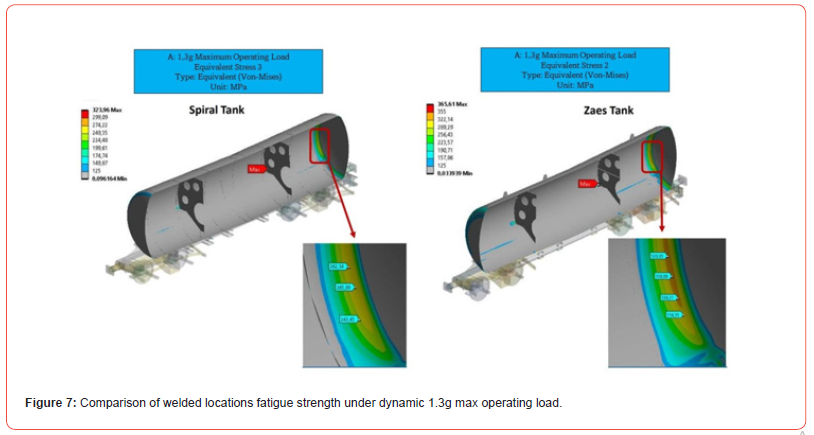
In Figure 7, the spiral welded tank wagon and the Zaes tank wagon are compared with the tests performed under dynamic loads at maximum operating conditions of 1.3g. Improvements were observed in the stress values obtained in critical locations in the spiral welded regions. Considering the obtained stress profile, the dynamic strength of spiral welded regions is higher than that of conventional tank welded regions. In the studies carried out, Von Mises stresses were at the highest level in the bonding and welding areas and were calculated to be greater than the safe stress of the material in cases where the design criteria were ineffective. Von-Mises stress in these regions can be controlled by changing the radius or increasing the thickness. It is important to ensure this control at the design stage by using analysis with the finite element method. Additionally, measuring critical deformations in stress concentration zones with strain gauges is another important approach for design improvement and verification of the design solution for the prototype [41]. Design and analysis, accurate mesh generation, material characteristics assignment, stress values, etc. and determination of the conditions are the crucial factors for the sensitivity of the results. Otherwise, strength model problems may be observed. It is not always possible to create a correct design approach based solely on analysis and results. For these reasons it is vital to determine which finite elements (shell or 3D solid) are used to create a FEM analysis and a computational model and that higher stress values provide greater similarity with test data. In addition, more precise and easier creation of geometry, clear visualization of structural elements, fewer restrictions in modeling, etc. advantages also need to be considered [48]. To solve such problems, concentration should be focused on performing strain-based simulations as well as stress-based approaches. Virtual strain gauges are also described as the finite element approach and are applied to verify the conditions like a real strain gauge. Therefore, the stress and strain results obtained by simulation can be considered as experimental results [49].
Conclusion
In this article, the fatigue strength of the spiral welded tank wagon was evaluated based on multiaxial stress principles. The paper focuses on APDL analysis for fatigue life evaluation of DVS1612 standard. The degree of utilization of the welded zones in the wagon are less than 1, and there was no probability of danger of fatigue failure. The targeting the utilization degree under 1 contributed effective fatigue design approach for tank wagons. All nodes located in the weld zone demonstrated sufficient dynamic strength. All safety coefficients in the nodes are greater than one. Analysis of theoretical data shows that there are no nodes with insufficient dynamic strength. According to the dynamic 1.3g max operating load spirally welded tank has demonstrated better performance than conventional ones.
Acknowledgement
The authors wish to thank FE-TECH Company for conducting the finite element analysis.
Conflict of Interest
The authors declare no conflict of interest in this work.
References
- RM Goverde, F Corman, A D Ariano (2013) Railway line capacity consumption of different railway signalling systems under scheduled and disturbed conditions. Journal of rail transport planning & management 3(3): 78-94.
- S Zhu, X Xu, Y Li (2022) Dynamic response of railway vehicle with aerodynamic admittance function: An optimized algorithm. Journal of Wind Engineering and Industrial Aerodynamics 227: 105075.
- Y Guo, Q Sun, Y Sun (2023) Dynamic evaluation of vehicle-slab track system under differential subgrade settlement in China's high-speed railway. Soil Dynamics and Earthquake Engineering 164: 107628.
- Y Bai, Z He, C Su, N Bao, H Wang, et al. (2022) Research on dynamic characteristics of novel filled damping block mesh-type rail pads for heavy haul railways. Construction and Building Materials 354: 129174.
- J Kim, J C Yoon, BS Kang (2007) Finite element analysis and modeling of structure with bolted joints. Applied Mathematical Modelling 31(5): 895-911.
- C Qu, Z Wang, L Wei, Y Xiao, Z Chang (2022) Field investigation of dynamic responses of a culvert-embankment transition zone in high-speed railway. Soil Dynamics and Earthquake Engineering 158: 107314.
- Y Shangguan, W Wang, C Yang, A He (2021) Fatigue Strength Evaluation of Welded Structure on Aluminum Alloy Car Body Based on Multi-Axial Stress.
- JAP Fernández (2017) Theoretical and experimental study of the fatigue behavior of large passenger transport vehicles under dynamic operating loads, in, Universidad Politécnica de Madrid.
- CL Niu, SM Xie, XW Li, W Wang (2019) Stress state grade evaluation method for welded joints of complex structures on railway rolling stock and its application in welded frame. Procedia Structural Integrity 22: 361-368.
- DVS, Technical Comittee, Working Group (2014) ‘Welding in railway vehicle manufacturing’. Technical Code DVS 1612. Design and endurance strength analysis of steel welded joints in railvehicle construction. DVS - German Welding Society.
- UIC (2012) UIC B 12/RP 17 9th Edition. WAGONS. Programme of tests to be carried out on wagons with steel under frame and body structure (suitable for being fitted with the automatic buffing and draw coupler) and on their cast steel frame bogies. UIC (International Union of Railways).
- D Li, B Uy, F Aslani, C Hou (2019) Behaviour and design of spiral-welded stainless-steel tubes subjected to axial compression. Journal of Constructional Steel Research 154: 67-83.
- CI Papadaki, G Chatzopoulou, GC Sarvanis, SA Karamanos (2018) Buckling of internally-pressurized spiral-welded steel pipes under bending. International Journal of Pressure Vessels and Piping 165: 270-285.
- MB Lin, K Gao, CJ Wang, AA Volinsky (2012) Failure analysis of the oil transport spiral welded pipe. Engineering Failure Analysis 25: 169-174.
- SHJ van Es, AM Gresnigt, D Vasilikis, SA Karamanos (2016) Ultimate bending capacity of spiral-welded steel tubes – Part I: Experiments. Thin-Walled Structures 102: 286-304.
- X Liu, Y Zhang, S Xie, Q Zhang, H Guo, et al. (2021) Fatigue failure analysis of express freight sliding side covered wagon based on the rigid-flexibility model. International Journal of Structural Integrity 12: 98-108.
- I Al Zamzami, L Susmel (2017) On the accuracy of nominal, structural, and local stress-based approaches in designing aluminium welded joints against fatigue. International Journal of Fatigue 101(2): 137-158.
- B Karabulut, B Rossi (2021) On the applicability of the hot spot stress method to high strength duplex and carbon steel welded details. Engineering Failure Analysis 128: 105629.
- F Guo, S Wu, J Liu, Z Wu, S Fu, et al. (2021) A time-domain stepwise fatigue assessment to bridge small-scale fracture mechanics with large-scale system dynamics for high-speed maglev lightweight bogies. Engineering Fracture Mechanics 248: 107711.
- Y Hu, S Wu, PJ Withers, H Cao, P Chen, et al. (2021) Corrosion fatigue lifetime assessment of high-speed railway axle EA4T steel with artificial scratch. Engineering Fracture Mechanics 245: 107588.
- C Schlehuber, M Heinrich, T Vateva-Gurova, S Katzenbeisser, N Suri, et al. (2017) Challenges and approaches in securing safety-relevant railway signalling, in: 2017 IEEE European Symposium on Security and Privacy Workshops (EuroS&PW), IEEE pp. 139-145.
- G Vatulia, A Falendysh, Y Orel, M Pavliuchenkov (2017) Structural improvements in a tank wagon with modern software packages. Procedia engineering 187: 301-307.
- A Gursoy, A Duman, A Erdogan, A Kaptan, M Yasar, et al. (2023) Design and finite element analysis of S355J2 wing holders on tank wagons. Journal of Design Against Fatigue 1: 42-52.
- A Babić, A Žukovski, V Jakovljevic, M Ivanovic (2012) CAD/CAA Modelling Assembly Operations of Tank Waggons.
- Y Dönmez, A Ermumcu (2023) Yılı İtibariyle Mimarlık ve Mühendislik Alanında Kullanılan Bilgisayar Programlarının İrdelenmesi, Gece Kitaplığı 1(364): 269-290.
- S Slavchev, V Maznichki, V Stoilov, S Enev, S Purgich (2019) Methodology for assessment of material fatigue in the area of welded joints of railway bogies by calculation. IOP Conference Series: Materials Science and Engineering 618: 012046.
- V Kraus, M Kepka, D Doubrava, J Chvojan (2019) Strength Analysis of Tramway Bogie Frame, in: J.A.F.O. Correia, A.M.P. De Jesus, A.A. Fernandes, R. Calçada (Eds.) Mechanical Fatigue of Metals, Springer International Publishing, Cham pp. 327-334.
- S Slavchev, V Maznichki, V Stoilov, S Enev, S Purgic (2018) Comparative analysis of fatigue strength of an y25ls-k bogie frame by methods of UIC AND DVS 1612, in: XVIII Scientific-Expert Conference on Railways RAILCON' 18: 1-4.
- B Vega, JÁ Pérez (2023) Comparative analysis of fatigue strength of a freight wagon frame. Welding in the World 68: 321-332.
- GE Street, PJ Mistry, MS Johnson (2021) Impact resistance of fibre reinforced composite railway freight tank wagons. Journal of Composites Science 5: 152.
- C Locovei, A Raduta, M Nicoara, LR Cucuruz (2010) Analysis of fatigue fracture of tank wagon railway axles, in: Proceedings of the 3rd WSEAS International Conference on Finite Difference–Finite Elements–Finite Volumes–Boundary Elements pp. 219-223.
- C Manzanares-Cañizares, C González-Gaya (2017) The integral management system 12 bookshelves. Procedia Manufacturing 13: 1059-1065.
- Y Shangguan, W Wang, C Yang, A He (2023) Fatigue Strength Assessment of an Aluminium Alloy Car Body Using Multiaxial Criteria and Cumulative Fatigue Damage Theory. Applied Sciences13: 215.
- FJ Bernal Lluch (2021) Optimization of the energy capture system through the third rail in a rolling stock vehicle. Solution p. 7.
- V Ralev, D Atmadzhova, Failure Analysis in Passenger Bogies from the Railway System of the Republic of Bulgaria.
- H Dong, B Zhao, Y Deng (2018) Instability phenomenon associated with two typical high speed railway vehicles. International Journal of Non-Linear Mechanics 105: 130-145.
- J Sun, E Meli, W Cai, H Gao, M Chi, et al. (2021) A signal analysis based hunting instability detection methodology for high-speed railway vehicles. Vehicle System Dynamics 59: 1461-1483.
- DP Connolly, GP Marecki, G Kouroussis, I Thalassinakis, PK Woodward, et al. (2016) The growth of railway ground vibration problems — A review. Science of The Total Environment 568: 1276-1282.
- TX Wu, DJ Thompson (2001) VIBRATION ANALYSIS OF RAILWAY TRACK WITH MULTIPLE WHEELS ON THE RAIL. Journal of Sound and Vibration 239(1): 69-97.
- SS Harak, SC Sharma, SP Harsha (2014) Structural Dynamic Analysis of Freight Railway Wagon Using Finite Element Method. Procedia Materials Science 6: 1891-1898.
- SS Harak, SC Sharma, SP Harsha (2015) Modal analysis of prestressed draft pad of freight wagons using finite element method. Journal of Modern Transportation 23: 43-49.
- XS Liu, P Wang, ZJ Yan, Q Wang, HY Fang, et al. (2012) Geometric Parameters Optimization Design for Aluminum Alloy Welding Joint Based on Increasing Fatigue Strength, in: Materials Science Forum. Trans Tech Publ pp. 1106-1111.
- B Miao, Y Luo, Q Peng, Y Qiu, H Chen, et al. (2020) Multidisciplinary design optimization of lightweight carbody for fatigue assessment. Materials & design 194: 108910.
- MM Topaç, S Ercan, NS Kuralay (2012) Fatigue life prediction of a heavy vehicle steel wheel under radial loads by using finite element analysis. Engineering Failure Analysis 20: 67-79.
- LH Zhao, QK Xing, JY Wang, SL Li, SL Zheng, et al. (2019) Failure and root cause analysis of vehicle drive shaft. Engineering Failure Analysis 99: 225-234.
- M Kubota, S Niho, C Sakae, Y Kondo (2003) Effect of understress on fretting fatigue crack initiation of press-fitted axle. JSME International Journal Series A Solid Mechanics and Material Engineering 46: 297-302.
- S Dou, Z Liu, L Mao (2023) An innovative fatigue life and critical defect size assessment method for structural components with pore defects. Journal of Mechanical Science and Technology 37: 3985-3998.
- PKV Rao, G Rama Prudhvi Varma, K Sri Vivek (2022) Structural dynamic analysis of freight railway wagon using finite element analysis. Materials Today: Proceedings 66: 967-974.
- JL San Román, C Álvarez-Caldas, A Quesada (2005) Structural Validation of Railway Bogies and Wagons Using Finite Elements Tools, Proceedings of the Institution of Mechanical Engineers. Part F: Journal of Rail and Rapid Transit 219: 139-150.
-
Gokhan Cil*, Fatma Mirza, Yusuf Oranci, Oguzhan Erdogan, Okan Unal. Investigation of fatigue strength evaluation of welded structure on spirally welded tank wagon via finite element analysis. Mod Concept Material Sci. 5(5): 2024. MCMS. MS.ID.000623.
-
Tank wagon, Fatigue, Welded zone, Strength, Finite element analysis, Multi-axial criteria, Geometry, Frequency
-

This work is licensed under a Creative Commons Attribution-NonCommercial 4.0 International License.


