 Research Article
The Use of Roller Blinds to Minimize Heat Dissipation of Buildings
Nora Muellner*, Bastian Baesch, Christoph Riethmueller and Goetz T Gresser
German Institutes for Textile and Fiber Research (DITF), Denkendorf, Germany
Nora Muellner, Technology Center Smart Living Textiles, German Institutes of Textile and Fiber Research Denkendorf, Germany.
Received Date:December 20, 2024; Published Date:January 15, 2025
Abstract
Interior solar shading systems are primarily used to protect against glare and overheating. However, the potential of the thermal insulation properties against cold outside temperatures has not yet been fully exploited [1]. Interior sun shading can be used to prevent the interior from cooling down [2]. When used correctly with internal roller blinds, the amount of energy required to heat or cool the interior can be reduced. The installation situation is decisive here.
Keywords:Cassette roller blind; Roller blind; Guide rail; Heat dissipation; Sun protection; Carbon footprint
Introduction
Sun shading can make a significant contribution to regulating
the indoor climate. Various studies show that adequate solar shading
can save between 6 million tons (IVRSA) and 22 million tons
(ESCORP-EU25) of CO2 per year throughout Germany [3,4]. These
figures are much higher worldwide. The differences between external
and internal solar shading systems can be summarized as
follows:
- External solar shading systems block the sun’s rays before
they enter the building, while internal solar shading systems
only block the sun’s rays after they have entered the building.
- External solar shading systems are more effective than
internal solar shading systems for reducing cooling loads (heat
load to be dissipated to maintain room temperature).
- Internal solar shading systems can help to reduce cooling
loads if they are highly reflective.
- Interior solar shading systems can help to reduce heating
loads. External solar shading systems do not reduce the heating
load.
- The mechanical requirements and therefore the price of
external sun shading systems are generally much higher than
for interior sun shading systems.
- There are several situations in which the use of external
solar shading systems is ruled out, e.g. in tall buildings due to
wind loads or on protected building facades.
- Interior solar shading systems are more suitable than exterior
solar shading systems for renovation measures that are
not aimed at replacing the facade and/or windows in a building
[5].
There are technical cases in which external solar shading cannot be used or can only be used with difficulty. This is for example in high-rise buildings due to strong wind exposure, in historic building facades and buildings that are part of an historic or architectural ensemble protection. In such situations, solar control glazing can be used in combination with or without internal shading. However, the energy efficiency and multifunctionality of conventional interior solar shading systems could be improved.
The standard DIN EN 52022 [6] specifies a method for calculating the energy properties of solar shading systems. DIN EN 13125 provides the basis for calculating the additional thermal resistance of shutters (interior and exterior solar shading systems that create additional layers of air at the window) [7]. This depends on the air permeability of the shutters and thus on the characteristics of the gaps at the connections to the building. The values for external roller shutters are calculated according to standards (in Germany and Europe), whereas only standard values are specified for various internal solar shading systems. In practice, however, the internal systems are installed in very different ways. As studies and calculation tools refer to this standard [8-11] the actual heat gains from such systems have so far been subject to considerable uncertainty [12].
A Test Measuring Room for Interior Sun Shading
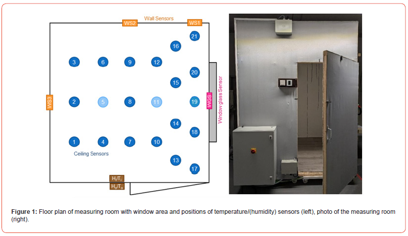
A closed measuring room with interior dimensions of 1.8 m x
1.8 m x 2.4 m was set up at DITF for tests. The room contains a
typical application window with adjustable reveal depth. A cooling
plate is installed in the window of the measuring room and can be
cooled via an integrated cooling coil with a refrigeration machine.
The window surface temperature can be adjusted with the aid of
the cooling element. A window sill can also be fitted. Heatable textile
elements were integrated into the walls of the measuring room.
Various heating situations can be created in the measuring room
by integrating conventional radiators. The tests presented here
were carried out with a heating panel whose heating output can
be adjusted via an electrical voltage. This heating panel is placed
under the window and is operated with an output of 32 W with
a heated area of 20 x 40 cm². The temperature distribution in the
room can be recorded using 21 temperature sensors distributed in
the volume and 5 on the walls. A number of humidity sensors are
also installed. All sensors and actuators in the measuring room are
integrated into a KNX bus system and their status is recorded every
minute via a data logger. Figure 1 shows the positions of the various
temperature sensors (roof sensors, wall sensors and window glass
sensor) from a bird’s eye view. The following sensors are installed:
• 2 x ceiling-mounted temperature sensor: PTDE0.01
• 6 x system temperature sensor wall/ceiling surface PTAN3.01
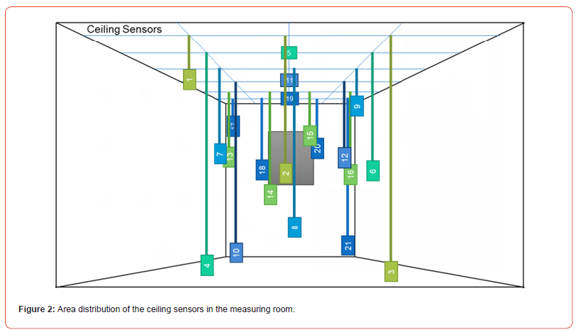
• 18 x PT1000 temperature sensor PTST3.01 (height-adjustable
built-in)
• 2 x temperature and humidity sensor TFS55.01
The PT1000 temperature sensors are height-adjustable in the room. The resolution of the built-in temperature sensors is 0.1 °C. For the following tests, these were set as in Figure 2. The ceiling sensors 5, 11 and 19 are of a different construction than the other ceiling sensors and can only be compared with each other.
Test Series Measurements with Roller Blinds in Different Installation Situations
The measuring room was used to carry out a series of tests on different installation situations with roller blinds in order to determine their actual properties under different convection conditions. In particular, the normative specifications of DIN EN ISO 52022 were tested. For operational reasons, an air-conditioned installation location of 23±2 °C was chosen for the measuring room. Temperature fluctuations of around ±2 °C were actually measured during the course of the day. As the temperature fluctuations over the course of the day showed a comparable pattern, it was still possible to make representative comparisons between the systems by using a time-coherent measurement sequence.
A cassette roller blind A with blackout fabric with optional guide rails and chain operation was installed in the measuring room and attached to the wall above the window in accordance with the manufacturer’s instructions. The reveal depth is 4 cm. The measuring room is brought to a starting temperature of 22 °C, then the test is started by closing the measuring room door. Initially, only the cooling plate on the window is set to 10 °C. After 4 hours of measurement, the heating is switched on with a heat output of 32 W and switched off after 13 hours the next day at the end of the measurement.
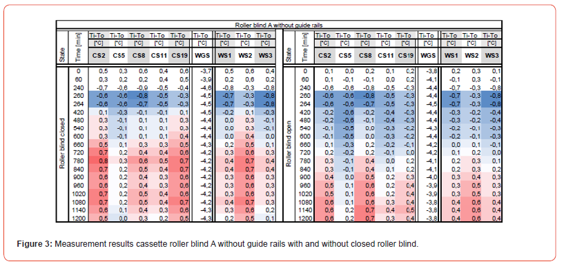
Temperature curves of selected sensors over the respective measurement period are used for the evaluation and one measured value is highlighted for each hour. These measured values are displayed in colored table cells for clear presentation. All values in a defined range are compared with each other and set in relation to each other. Values in this range that are the highest are shown in red, values that are the lowest are shown in blue. Values in between are graded by color. The ceiling sensors CS2, CS5, CS8, CS11, CS19 and the wall sensors WS1, WS2, WS3 are shown below. The window glass sensor WGS measures the temperature directly on the window glass surface.
The laboratory temperature of the ambient air in the measuring room fluctuates around 23±2 °C in the air conditioning area with a similar daily pattern. This fluctuation is also transferred to the measurement results in the measurement room. For this reason, relative temperatures (Tindoor-Toutdoor) are discussed below (Table 1). The measurements carried out can be summarized as follows:
Table 1:Settings of the measurement series performed.

Comparison 1:
The measured temperature differences (Ti-To) for roller blind A without guide rails with and without closed roller blind are shown in Figure 3, The first four hours the temperature drops because of the cooling of the window. Then the heating is switched on. Due to the low power of the heater, the measuring room needs some time to become warmer than the starting temperature. For the selected sensors in Figure 3, a faster and overall higher temperature rise can be seen for the condition with the roller blind closed (left). The window glass temperature drops further at the end when the roller blind is closed, while it rises again when the roller blind is open.
Comparison 2:
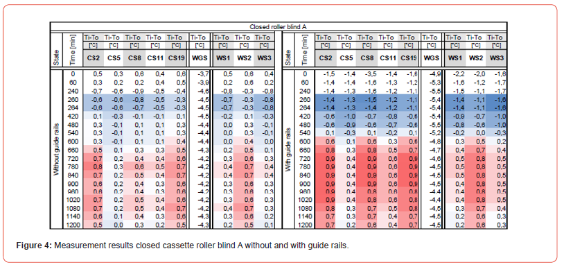
Figure 4 shows the comparison of roller blind A with and without guide rails when the roller blind is closed. The use of guide rails leads to a significantly higher temperature in the measuring room. The window glass temperature also reaches lower values in the setup with guide rails. The temperature differences between the sensors can be explained by the different design and position in the room. The temperatures tend to be higher the closer the sensor is to the heating panel and the higher it is installed.
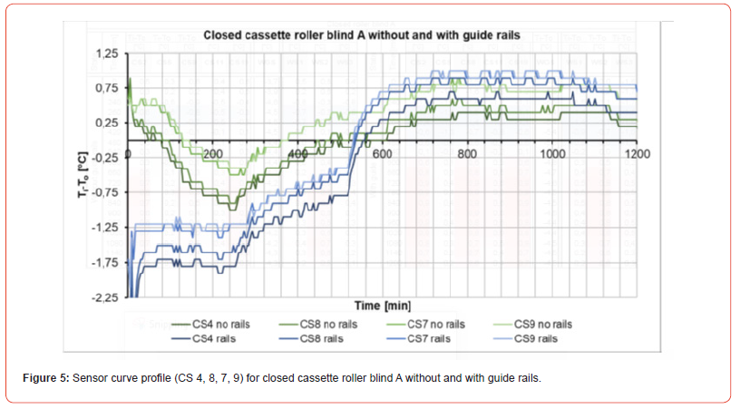
Figure 5 shows the curves of the ceiling sensors CS4, CS8, CS7 and CS9 over the entire measurement period in ascending order to the floor. It can be clearly seen that higher temperatures were measured for the sensors close to the ceiling than for the sensors close to the floor. In addition, the higher internal temperature can be seen for roller blind A with guide rails. Although the measuring room was colder at the start of the measurement than for roller blind A without guide rails, the internal temperatures reach higher values after a certain measurement period.
Comparison 3:
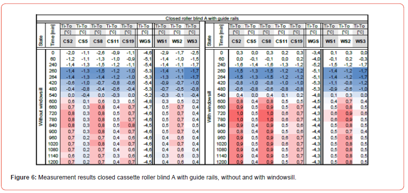
In a further test, the influence of a window sill was investigated. The window sill is placed in the reveal in the same way as a standard window. It protrudes 12 cm into the room and thus protrudes beyond the heater, which is located under the window. Figure 6 clearly shows the influence of the window sill and thus a complete ly closed air volume. Despite the low power input via the heating panel, the room heats up faster and more strongly. The difference is particularly noticeable at the back of the room.
Conclusion
In the private, public and commercial sectors (offices, schools, etc.), shading plays an important role in protecting interior spaces from glare, overheating and cooling. However, the energy efficiency potential of conventional interior sun shading systems is not yet fully exploited [13] and the installation situations have not been sufficiently investigated. This work shows that the installation situations have a significant influence on the thermal insulation properties against cold outside temperatures. The use of guide rails and fully closed air volumes, for example by the installation of a window sill, lead to better thermal insulation and less cooling of buildings. In future, further series of measurements will be carried out in the new measuring room in order to characterize other interior sun shading systems and to develop new interior sun shading systems with improved thermal insulation properties.
Acknowledgement
The project was part of the IGF project “Convection-compatible interior sun protection to minimize heat emission” 22580 N of the Forschungsvereinigung Forschungskuratorium Textil e.V., Reinhardtstraße 12-14, 10117 Berlin, funded by the Federal Ministry for Economic Affairs and Climate Protection as part of the programme for the promotion of Industrial Collective Research (IGF) on the basis of a resolution of the German Bundestag. We are grateful for this support.
Conflict of Interest
No conflict of interest.
References
- Tilmann E Kuhn, Christopher Bühler, Werner J Platzer (2001) Evaluation of overheating protection with sun-shading systems. Solar Energy 69(Supplement 6): 59-74
- Post H (2013) Unsicherheit bei der Planung von Sonnenschutzsystemen Bauphysik 24(2).
- Unbekannter Autor, Energieeffizienz durch Sonnenschutz, Sicht-Sonnenschutz 5/2021, S.38
- (2020) Unbekannter Autor, Wie Deutschland 22 Millionen Tonnen CO2 einsparen kann, Sicht- Sonnenschutz 1/2020, S.31
- European Solar Shading Organization (ES-SO): Energy saving and CO2 reduction potential from solar shading systems and shutters in the EU-25 (ESCORP-25), 2006 (Online unter: https://bvst.at/images/pdfs/ESCORP-EU25.pdf; Datum des Zugriffs: 31.3.2021)
- DIN EN ISO 52022-1:2018-01. Energieeffizienz von Gebäuden - Wärmetechnische, solare und tageslichtbezogene Eigenschaften von Bauteilen und Bauelementen - Teil 1: Vereinfachtes Berechnungsverfahren zur Ermittlung der solaren und tageslichtbezogenen Eigenschaften von Sonnenschutz in Kombination mit Verglasungen (ISO 52022-1:2017); Deutsche Fassung EN ISO 52022-1:2017
- DIN EN 13125:2001 Abschlüsse – Zusätzlicher Wärmedurchlasswiderstand – Zuordnung einer Luftdurchlässigkeitsklasse zu einem Produkt. Deutsche Fassung EN 13125:2001.
- (2017) European Solar-Shading Organization: Solar Shading for low energy and healthy buildings. Version 2, Februar 2018. ES-SO, Zaventem.
- J Schlitzberger (2018) Leitfaden Denster mit Abschlüssen im Bestand. Studie im Auftrag der Industrievereinigung Sonnenschutz-Rolladen-Automation (IVRSA) im Industrieverband Technische Textilien – Rolladen – Sonnenschutz e.V. (ITRS). Kassel.
- M Rossa, M Demel, J Benitz-Wildenburg, M Freinberger (2015) Sonnenschutz – Mehr als Licht und Schatten. Komfort, Energieeffizienz und Sicherheit durch Technik, Funktionalität und Qualittät. Sonderschau “Mahr als Licht und Schatten!“ ift Rosenheim.
- (2022) Textinergie – Energy savings with textile blinds. Berechnungstool.
- L Venturi, D Andrews, Z De Grussa, I Chaer (2018) The Challenge of Modelling Solar Shading Products and Their Impact on the Built Environment. CIBSE Technical Symposium: London.
- (2021) Guidhouse Germany GmbH: Solar shading – Synergising mitigation of GHG emissions and adaptation to climate change. The potential to disrupt rising cooling de-mand and overheating in European buildings. Berlin, Germany.
-
Nora Muellner*, Bastian Baesch, Christoph Riethmueller and Goetz T Gresser. The Use of Roller Blinds to Minimize Heat Dissipation of Buildings. J Textile Sci & Fashion Tech 11(2): 2025. JTSFT.MS.ID.000759.
-
Cassette roller blind, Roller blind, Guide rail, Heat dissipation, Sun protection, Carbon footprint
-

This work is licensed under a Creative Commons Attribution-NonCommercial 4.0 International License.


