 Opinion
Fundamentals of Structure Ball Winding Technology - Characterization of Structure Ball Winding Types
Dr.-Ing. Kathrin Haigis*, Christoph Riethmüller and Prof. Dr.-Ing. Götz T Gresser
German Institutes for Textile and Fiber Research (DITF), Denkendorf, Germany
Dr.-Ing. Kathrin Haigis, Smart Living Technology Center, German Institutes for Textile and Fiber Research (DITF), Denkendorf, Germany.
Received Date:December 07, 2023; Published Date:December 15, 2023
Abstract
Structure ball winding technology is an economical technology for the production of three-dimensional lightweight components. By categorizing different types of winding and with an understanding of the geometric relationships and the balling principle, various new types of winding can be easily developed and adapted to new applications.
Keywords:Structure ball winding; Flyer; Flyer path; Winding types; Mandrel; Yarn placement; Structure ball winding component
Opinion
Structure ball winding technology is derived from conventional balling technology. It is an economical method for producing three-dimensional lightweight components.
Conventional balling technology is an established method for the automated production of balls of yarn. It is often used to produce yarn balls for household and commercial applications. Relevant ball shapes are, for example, tubeless hard balls for twine yarns in handicrafts, round balls for paper yarns and soft balls for hand knitting yarns [1]. Consequently, development work on conventional balling concentrates on optimizing the existing balling process with regard to economic aspects and the presentation of the product.
Structured balls are three-dimensional structures in which the yarn is deposited on a mostly spherically curved surface. In contrast to structural winding components [2], windings can also be deposited transversely to the axis of rotation of the mandrel and thus in all spatial directions. In structure ball winding, an s-shaped flyer, through which the yarn is guided, rotates around a rotating mandrel body. This is inclined at a defined angle to the axis of rotation of the flyer so that the angle enclosed by both axes is less than 90°. Structured balls therefore have a defined yarn placement. Here, the yarn placement points on the mandrel body are matched to the mandrel body and the application of the component. Variable mandrel body shapes can be created using pneumatic or hydraulic textiles. These can be used in the structural tangle process to produce even complex shapes [3]. The yarn is typically not removed from the mandrel body in the case of structure balls. If the placed yarns are consolidated in a subsequent process step, this is referred to as a structure ball component. Structured balls can have closed windings but pronounced rib and grid structures are also implemented [4,5].
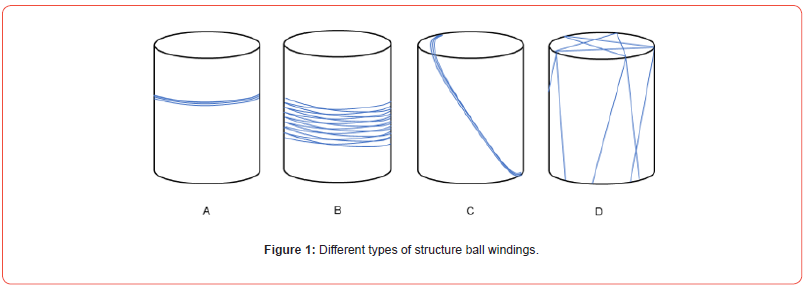
Four different types of winding can be created in the structure ball winding process. In the main structure winding (D, compare figure1), yarn is laid down in all spatial directions. In addition, the three partial wrappings of the belly wraps (A), structural circumference wrappings (B) and strand wrappings (C) can be created, which are to be understood as components of structured balls.
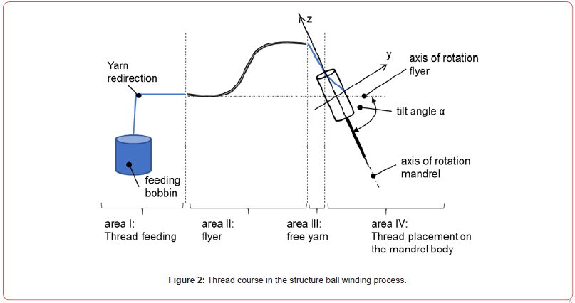
The yarn path can be divided into four areas:
I: Thread feeding
II: flyer
III: free yarn
IV: thread placement on the mandrel body
Deflection and yarn guiding elements that influence the basic yarn tension can be installed in the yarn feed. In addition, the bobbin unwinding forces [6-8] and the air resistance of the moving yarn influence the yarn tension in the process. The subsequent flyer area is defined by the flyer itself, which has the radius rF. The area of the free yarn begins at the eyelet of the flyer until the yarn runs onto the mandrel body. In this area, most of the air resistance-induced yarn tensions arise, analogous to the balloon forces during wrapping [9]. The yarn is finally placed on the mandrel body (Figure 2).
Materials and Methods
Materials and sample preparation
In this study, a high crystal PP block copolymer (JSS-350N, LOTTE Chemical, Re-public of Korea) with a melt flow rate of 10g/10min, rubber such as ethylene-octane copolymer elastomer (Engage8842, Dupont Dow Elastomer, USA) with a melt flow rate of 1.0 g/10 min and density of 0.86 g/cm3, talc (IMIFABI) with an average particle size 0.5 μm, and two types of lubricants, magnesium stearate (Mg-st) and calcium stearate (Ca-st), with a molar mass of 500 g/mol (SD Korea, Republic of Korea) were used as received.
The composition of the PP compounds prepared in this study is listed in Table 1. To determine the additive migration mechanism, the composition ratio of stearic acid alone, mainly used in the automotive industry, was considered in this study for accurate measurement.
Table 1:Composition of the PP compounds prepared in this study Composition (wt%).

Under annealing conditions, we prepared three-mm-thick injection- molded specimens to demonstrate how additives diffuse to surfaces over time. Samples were annealed at 70 °C for 0, 24, 48, and 72 hours. For examining additive migration, specimens sized 127 mm × 127 mm x 3.0 mm were manufactured and then split into 10 mm × 10 mm × 1.0 mm samples to confirm the characteristics of additive migration between the interior and exterior specimens after accelerated thermal aging. These experiments were performed under the assumption that the internal additives diffused outward under the annealing conditions. Thus, the difference between each surface of the specimen can be identified. As part of this investigation, surface X-ray diffraction (XRD) and differential scanning calorimetry (DSC), as well as energy dispersive X-ray spectroscopy (EDS), were conducted on internal and external specimens to better understand additive migration. Figure 1 illustrates the sample preparation sequence.


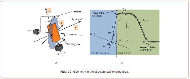
The flyer is the main thread guide element and, together with the mandrel body and the knotting settings, defines the position of the thread placed on the mandrel body. The flyer rotates around the flyer rotation axis during structural tangling. It passes through flyer angles φ between 0° and 360° per revolution. The eyelet at the end of the flyer thus describes a flyer path with the radius rF. To ensure that the yarn is placed on the mandrel body, the plane through the flyer path must intersect the mandrel body. To ensure that the yarn is placed on the end face, the plane must intersect the end face of the mandrel body through the flyer path (Figure 3).
The flyer path represents an elliptical path in the coordinate system shown in figure 3. In order to calculate the thread placement, it is necessary to know the exact position of the eyelet (marked with an A in figure 3). This follows the following coordinates (xA, yA, zA) in the coordinate system under consideration. The geometric relationships shown in figure 3 also apply here.

𝑥𝐴=𝑟𝐹∙cos 2𝜋−𝜑
𝑦𝐴=𝑠𝑖𝑛β∙𝑟𝐹∙sin 2𝜋−𝜑 +𝑦𝑀
𝑧𝐴=𝑐𝑜𝑠β∙𝑟𝐹∙sin 2𝜋−𝜑 +𝑧𝑀
M… Center of the flyer path with the coordinates (xM, yM, zM)
U… Origin of the coordinate system
α… tilt angle of the mandrel body
β… Auxiliary angle between line d and the z-axis
φ… flyer angle
The coordinates of the eyelet formed the basis for a calculation approach for the yarn deposition in structural tangling, with which the influence of the process parameters can be determined without empirical tests. The basis for this is the constant rotational movement of the flyer around the also constantly rotating mandrel body. With knowledge of the influence of the ball parameters and the mandrel body contour, the yarn position can be calculated using the developed algorithm, which does not require complex simulation software. This provides an important basis for the resource-optimized development of three-dimensional structural tangle components for technical applications.
The basis for the calculation models is the following calculation principle.
At the beginning of the structure ball winding process, the yarn is fixed at a defined point (starting point) (1). The yarn is drawn off due to the rotational movements of the mandrel and the roving frame. Due to the relative movement, the process parameters (speed ratio h, tilt angle α) and depending on the mandrel body shape, the yarn touches the mandrel body at the newly found placement point on the mandrel body (2). This found placement point is used as the new starting point. The calculation is repeated until all the required placement points have been found (3).
Various positional relationships between geometric points whose positions in the coordinate system are known are used as the basis for calculating the storage position. These in turn lead to intersection problems, the solution of which is provided by the storage points [10].
The structure of structural main developments can be described by the number and position of intersection points. The speed ratio h represents the ratio between the speed of the flyer (nF) and the mandrel (nD). This value also determines the position of the crossing points and thus the structure of the structural winding.
The following applies
h=𝑛𝐹/𝑛𝐷= 𝑓/𝑑𝐿
f… Number of flyer revolutions per deposited layer
dL… Number of mandrel revolutions per deposited layer
nF… Speed of the flyer in rpm
nD… Speed of the mandrel in rpm
If the speed ratio is displayed as a fraction, the number of flyer revolutions f and the number of mandrel revolutions dL per deposited layer can be read off. Depending on the speed ratio, the main structural windings can be divided into straight and wild structural windings. Straight structure windings are characterized by an integer speed ratio. Small values form close-meshed lattice structures, large values wide-meshed ones. Wild structure windings are characterized by a non-integer speed ratio. Depending on the speed ratio h, they can quickly form closed surfaces, i.e. surfaces in which the outer contour of the mandrel body is almost completely covered with yarn. This makes the lattice structures more difficult to differentiate from one another and they often appear irregular.
In this way, winding strategies can be developed in a simple analytical way, which assign the correct structure to different areas of the structure ball winding component.
Acknowledgement
This research work is sponsored by DITF Denkendorf.
Conflict of Interest
Authors declare no conflict of interest.
References
- (1972) Anonym: Eine leistungsstarke Langknäuel-Spulmaschine. Textilbetrieb, März, Seite 82
- Riethmüller C, Baesch B, Planck H (2011) Strukturspulen – neues Verfahren zur Herstellung intelligenter Bauteile. Melliand Textilberichte 2: S. 85.
- Burmeister S, Riethmüller C, Gresser GT (2023) Self-Organizing Hydraulic Textiles for Multiple Room Use. J Textile Sci & Fashion Tech 10(1): 1-2.
- Scharpf K, Riethmüller C, Gresser Götz T (2016) wirtschaftliche Herstellung von Bauteilen durch die Strukturspul- und Strukturknäueltechnik, Technische Textilien 4: S. 170.
- Haigis K, Riethmüller C, Finckh V, Gresser GT (2023) Structure-Winding Components Made of Paper Yarn for Construction Applications. J Textile Sci & Fashion Tech 10(1): 1-2.
- Weinsdörfer H (2004) Final report on the research project “Ermittlung der Spulenablaufparameter zur Optimierung des Ablaufverhaltens beim Hochleistungsweben”.
- Riethmüller C (2011) Final report on the research project AiF 15923 N, Entwicklung einer neuen Spultechnologie bei Färbespulen zur Erschließung breiter, direkter Einsatzmö
- (2006) Final report on the collaborative project “Pilotentwicklung eines Linear-Changierantriebs für die Herstellung von Rotorgarnspulen mit verbessertem Ablaufverhalten für die Hochleistungsweberei”, ITV Denkendorf.
- Riethmüller C (2015) Final report on the research project IGF 17819 N “Innovative Umwindetechnologie für sensorische Garne”.
- Haigis K (2022) Grundlegende Ermittlung von Struktur-Eigenschaftsbeziehungen beim Strukturknäuelprozess für technische Anwendungen, Dissertation, University of Stuttgart, Germany.
-
Dr.-Ing. Kathrin Haigis, Christoph Riethmüller and Prof. Dr.-Ing. Götz T Gresser. Fundamentals of Structure Ball Winding Technology - Characterization of Structure Ball Winding Types. J Textile Sci & Fashion Tech 10(2): 2023. JTSFT.MS.ID.000735.
-
Structure ball winding, Flyer, Flyer path, Winding types, Mandrel, Yarn placement, Structure ball winding component
-

This work is licensed under a Creative Commons Attribution-NonCommercial 4.0 International License.


