


 Short Communication
Wind Turbine and Tidal Turbine Technological Innovation
Received Date:June 19, 2026; Published Date:July 01, 2026
Short Communication
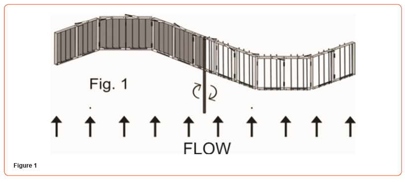
This project is an innovation of a vertical-axis, foldable and multi-configurable tidal wind turbine. Patent MX/a/2023/006829 PATENT TITLE No. 424578. It is closed, it efficiently takes advantage of low winds and lower speeds, it is a multi-configurable folding turbine and being the semi-cylindrical concave shape the shape that most opposes the passage of a flow, it is convenient to configure it in a concave way, it can reduce the wind speed by up to a fifth, which would mean that it extracts up to 80% of its kinetic energy, breaking Betz’s theorem that says that only a maximum of 59.3% of its kinetic energy can be extracted, a theorem that can be applied to horizontal axis turbines and not to this one that in addition to being vertical axis is closed and concave. The concave configuration in Fig. 1 rotates clockwise.
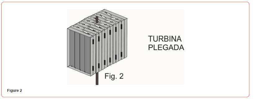
In Fig. 2 you can see the tidal wind turbine already folded to shelter from strong winds, or to be transported more easily, the folding of the turbine can be manual or by automated system that by means of an anemometer detects high wind speeds and activates the pistons that can be electric, pneumatic or hydraulic. https:// turbinasfletes.com/
Some prototypes are on social networks: http://www.linkedin. com/in/jorge-fletes-0972a4252 https://www.youtube.com/@ jorgefletes5681 https://www.instagram.com/turbinafletes/
The turbine of this project solved the problem that the semicylindrical Savonius turbine Rotor Savonius has had for a century - Wikipedia, the free encyclopedia which although it efficiently takes the force of the wind from its concave part, its convex part wastes much of that force when impacting against the wind, the speed of the impact being the sum of the velocity of the flow and the speed of the turbine, not so with our turbine of this project that its convex part opens to let the wind pass when it comes back against the wind, this is because of the way the central axis blades are configured, of lateral axis and the stops that are magnetic with magnets, one on the top and one on the blade in a way that they repel each other and make the turbine very quiet because the stop stops the blade without making physical contact, the frames obstruct the wind in one direction and in the other let it pass.
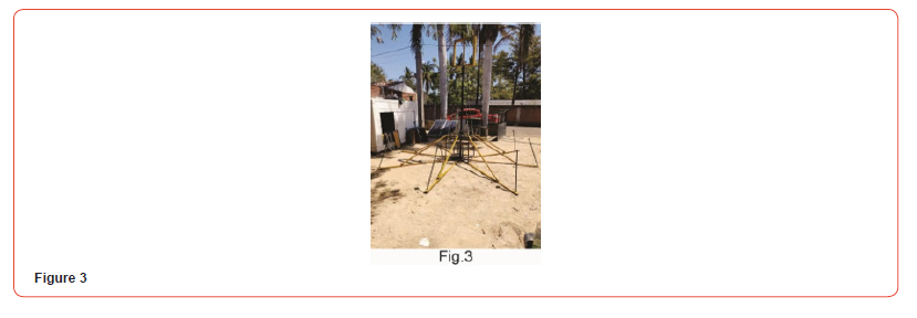
We are building a base prototype Fig. 3 to test rotors of various sizes, starting with a rotor with square frames of 70 centimeters and 18 frames per arm, it would be approximately 9 square meters of the arm that stops the wind, if the wind power at a speed of 8 m/s, is 314 W per square meter, It would be 314 x 9 = 2,826 watts, reducing the losses would generate about 2 KW, but if the same number of frames but 2 meters per side and at the same speed would give a 8 times higher power around 16 KW.
This base has eight horizontal arms at ground level and at the tip of each arm a perforation, so that they can be fixed to the ground by means of large nails. In the upper part the central frame to which the 18 frames for each arm will be attached by means of hinges, in the lower part the speed multiplier and the electric generator. You can also see four steel cables that reinforce the central axis and in the upper part where the cables are fixed there is a conical bearing that supports both radial and axial forces.
Acknowledgement
None.
Conflicts of Interest
No conflicts of interest.
-

This work is licensed under a Creative Commons Attribution-NonCommercial 4.0 International License.