


 Research Article
Study on Initial Rotational Stiffness of End Plate Connection Joints Considering Slab Effect
Received Date:January 28, 2026; Published Date:February 18, 2026
Abstract
To investigate the initial rotational stiffness of endplate connection joints, quasi-static tests were conducted on one bare joint and one endplate connection joint considering the slab effect. The contribution of each component to joint stiffness was determined through the component method, and the stiffness calculation formula for each component was provided based on existing research results. Based on the influence of component deformation on the overall deformation of joints, a calculation model for the initial rotational stiffness of endplate connection joints considering the slab effect was constructed, and corresponding theoretical calculation formulas were derived. In addition, a numerical model was established using the finite element method to obtain initial rotational stiffness data, and the analysis results were compared with theoretical calculation values to verify the correctness and effectiveness of the calculation method proposed in this paper. The results show that the consideration of slab effect can increase the initial rotational stiffness of joints by approximately 5% to 19%, demonstrating the importance of incorporating slab effects in semirigid joint design.
Keywords:Slab effect; Initial rotational stiffness; Finite element method; Component method
Introduction
Steel frame structures are widely used in engineering practice due to their excellent seismic performance and construction advantages [1-4]. Joint stiffness is a crucial factor affecting overall structural performance, and reasonable consideration of joint stiffness can reflect the actual force state and improve design accuracy. However, traditional joint stiffness calculations often neglect the contribution of floor slabs [5]. Research has shown that floor slabs can significantly enhance joint rotational stiffness [6], with the rotational stiffness of composite joints ranging from 87% to 106% higher than that of bare joints. Azadeh Haghighat [7] conducted experimental research on composite joints with floor slabs, revealing that floor slabs substantially increase both the load-bearing capacity and stiffness of joints. Similarly, Beatriz Gil [8] studied three-dimensional semi-rigid composite joints and compared the test results with EC4 code predictions. Amsyar Faisal [9] investigated semi-rigid composite beam-to-column joints for cold-formed steel frames through experimental and numerical studies. Hamed Keikha [10] evaluated the seismic performance of novel bolted flush end-plate beam splice connections. Monique C. Rodrigues [11] experimentally assessed the shear connector component of composite joints and compared the results with EC3 code provisions.
In view of this, to better reflect the actual working performance of joints, this paper considers the influence of floor slabs on joint rotational stiffness. One bare joint and one composite joint specimen were designed and fabricated, and quasi-static tests were conducted to analyze the rotational stiffness variation patterns and establish a theoretical calculation method for initial rotational stiffness.
Experimental Program
Specimen Design
Two full-scale specimens of end plate connection joints and one composite joint specimen were designed and fabricated. The specimens were designated as Maj-F (with floor slab) and Maj- NF (without floor slab). Both specimens had identical dimensions and configurations. The column was rigidly connected to the foundation, and the joint connection details are shown in Figure 1. The dimensions of the joints were identical, with specific geometric parameters provided in the experimental setup.

Loading Protocol
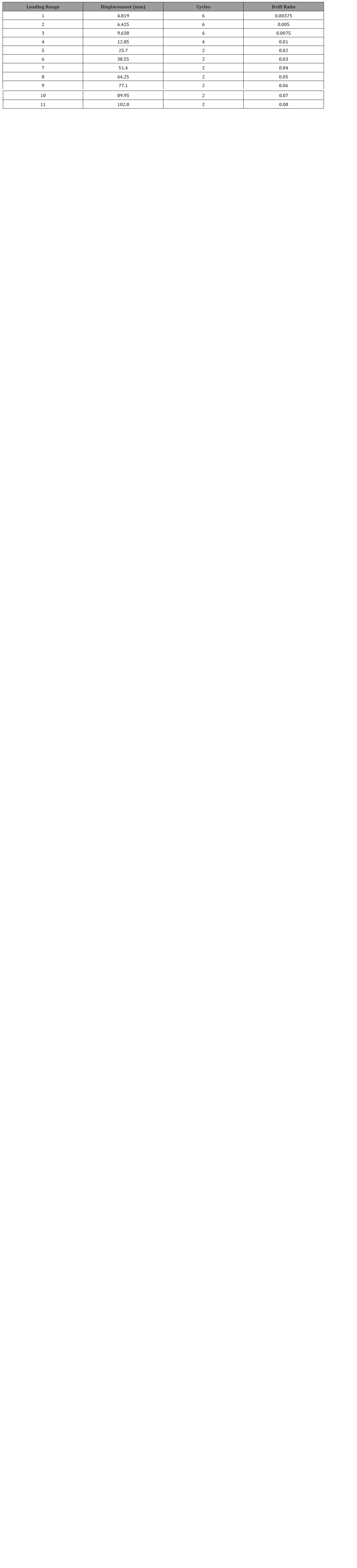
The experiment used displacement loading, and the loading regime was formulated according to the American Seismic Design Code for Steel Structures [12]. The ratio of the vertical displacement at the beam end to the beam length was used as an approximation of the inter-story drift, and this was used as the basis for controlling the loading. During the experiment, a hydraulic jack was first used to apply an axial pressure of 1250 kN at the top of the column with an axial pressure ratio of 0.3. Then, the pre-set axial pressure was kept constant, and repeated loading and unloading were performed using the MTS device connected to the beam end. The experiment was stopped when the specimen fractured or the bearing capacity dropped significantly to 85% of the maximum value. The specific loading regime is shown in Figure 2, and the loading displacement is shown in Table 1.

Table 1:Loading protocol for specimens.

Test Observations
The failure phenomena of specimen Maj-F from the start of loading to the end are as follows: the anchorage end of the concrete floor slab completely loses its working performance, the end plate buckles, slippage occurs between the steel beam and the concrete floor slab, fish scale lines appear on the weld at the connection between the end plate and the steel beam, the high-strength bolts loosen or break, and small shear deformation occurs between the nodal areas. The failure of Maj-F is shown in Figure 3.
For specimen Maj-NF, the failure process was as follows: When the displacement reached approximately 5 mm, obvious deformation began to occur in the joint region, and as loading continued, deformation became more pronounced. The final failure mode is shown in Figure 4.

Test Results
As shown in Figure 5 and Table 2, the moment-rotation (M- θ) hysteresis curves of both specimens exhibit pinching, mainly due to slippage between the concrete slab and the steel beam, and bond slippage between the reinforcing steel and the concrete.
Considering the composite effect of the slab, the compressive strength of the composite joint is significantly improved compared to the bare joint, and the tensile strength is also substantially increased. The positive initial stiffness of the Maj-F direction is 30% greater than that of the negative direction, and the negative yield moment is 25% greater than that of the positive yield moment.
Table 2:the bearing capacity and initial stiffness of the test specimens.

Note:K represents the initial stiffness, in kN·m·rad⁻¹; My, Mmax, and Mu represent the yield moment, peak moment, and ultimate moment, respectively, in kN·m; θy, θmax, and θu represent the yield rotation, peak rotation, and ultimate rotation, respectively, in rad⁻¹.

Theoretical Analysis of Initial Rotational Stiffness
Component Method
Column Web Compression and Shear Stiffness:Transverse stiffening ribs are designed at the alignment point between the column web and beam flange. These ribs function to withstand compressive or tensile forces transmitted from the beam flange. The calculation methods for the web’s compressive and tensile stiffness are equivalent. As specified in reference [13], the compressive and tensile stiffness values of the column web can be derived as Eq. (1).
Where ta and tb represent the thickness and width of the column’s transverse stiffeners; E denotes the elastic modulus of the column web; twc indicates the thickness of the column web; υ is the Poisson’s ratio; hwc is the height of the column web; bwc is the effective width of the web’s, and the value is obtained by using Eq. (2).
Where tfb is thickness of the I-beam girder flange; hep, f is effective height of the weld between the steel girder and end plate; tpe is end plate thickness; tfc is column flange thickness; hef, f is effective height of the weld connecting the column flange to the web.
Shear force is the primary factor causing deformation in the node domain, while the effect of bending moment is negligible. Therefore, according to the literature [13], the shear stiffness of column webs is obtained by Eq. (3).
Where Avwc denotes the effective shear area of the column web; Zcwv represents the vertical distance from the reinforcement axis to the center point of the lower flange when calculating the shear zone height under negative bending moment. Conversely, under positive bending moment, this height is determined by the vertical distance from the last row of bolts to the concrete surface.
End Plate in Bending:As specified in EC3 [13], the width of the equivalent T-stub connection for endplates shall be equal to the beam flange width, as shown in Table 3. Each parameter of the calculated model is shown in Figure 6.
Table 3:Effective length of equivalent T-shaped piece.


When considering the effect of bolt preload, the bending stiffness of T-shaped column flange is determined according to reference [14], as shown in Eq. (4).
Where lcf=2mc, where mc is the distance from the bolt center to the column web edge; tcf is the column flange thickness; Icf=lcf·tcf3/12; Ebo is the bolt’s elastic modulus; Abo is the bolt’s cross-sectional area; lcf is the calculated span of the column flange’s T-stub simply supported beam model, with lcf = 2(ec + mc). When considering the effect of bolt preload, the bending stiffness of the T-shaped component end plate is determined according to reference [13] as shown in Eq. (5).
Where lep,=2me (where me is the distance from the bolt center to the web); Eep is endplate elastic modulus; Iep is end plate moment of inertia; leff, ep is endplate width corresponding to the T-stub; tep is end plate thickness; Ebolt is bolt elastic modulus; Abolt is bolt crosssectional area.
Tensile stiffness of steel bars:The tensile stiffness of steel bars is specified as EC4 [14], as shown in Eq.(6).
Where Er denotes the elastic modulus of HRB400 steel bars; Ar represents the total cross-sectional area of longitudinal reinforcement bars for HRB400. As specified in EC4 [13]standard, lr is the half the column’s cross-sectional height.
Compressive stiffness of concrete slab:When calculating the initial rotational stiffness, the compressive stiffness of concrete cannot be ignored, but its tensile effect can be ignored. According to reference [14], the compressive stiffness of concrete is obtained by using Eq. (7).
Where ES and Ec represent the elastic modulus of steel column material and concrete floor, respectively; bsl is the thickness of concrete floor used as the flange width of T-stub; lsl is the height of column section used as the flange length of T-stub.
Bolt Tensile Stiffness:When calculating the flexural stiffness of column flanges and end plates, bolt stiffness should be considered. According to EC3 [13] specifications, the tensile stiffness of singlerow bolts (two) of the T-stub is calculated by Eq. (8).
Where lbolt denotes the calculated length of the bolt shank, with the formula: lbolt=tep + tfc + 2twh + (th + tn)/2. Here, tep and tfc represent the thickness of the endplate and column flange respectively; twh is the gasket thickness; th and tn are the thickness of the nut and bolt head respectively; Abolt is the effective tensile area of the bolt.
After calculating the stiffness of each component individually, the components must be assembled to determine the initial rotational stiffness of the joint. Figure 7 illustrates the computational model for the stiff axis joint, where the following parameters are defined: column web tensile deformation (cwt), column flange bending deformation (cfb), end plate bending deformation (eb), bolt tensile deformation (bt), column web compression deformation (cwc), column web shear deformation (cws), concrete floor compression deformation (sl), and concrete floor longitudinal reinforcement tensile deformation (sr). The component distribution is illustrated in Figure 4.

In this calculation process, the assumption of a flat cross-section is maintained. When the connection area is in the elastic stage, the tensile area causes an overall displacement Δt under external load, which can be obtained by summing up the displacements of each component. Δcf and Δep account for the influence of bolts, thus, the overall displacement Δt can be obtained by using Eq. (9).
When subjected to bending moment M, the steel bar experiences tensile force at Zeq, while the endplate bends and the web and bolts also bear tensile forces. The total tensile deformation Δt caused by using Eq. (10).
The compressive deformation Δc of the column web is calculated by Eq. (11).
Assuming that the shear force of the column is entirely applied to its web, the web will develop a certain amount of shear deformation in the Zeq height region, as shown in Eq. (12).
Thus, the equation for calculating the relative rotation(θ) of the joint is derived as Eq. (13).
The initial rotational stiffness of the overall joint is calculated by using Eq. (14).
Finite Element Analysis
Finite Element Model
A full-scaled 3D model of the endplate connection joint was established using the finite element software ABAQUS. All components used C3D8R element type, while the reinforcing bars used T3D2 elements. Based on the actual size of the bolts and joint regions, the element lengths of the bolts are 8 mm, while other parts had element lengths of 20-40 mm (as shown in Figure 8). The steel used was Q355B, and the constitutive relation was a threesegmented elastoplastic constitutive model. The elastic modulus was 206,000 MPa, and Poisson’s ratio was 0.3, and the plastic strain was 0.1. The bolt yield stress and tensile ultimate stress were 940 MPa and 1130 MPa, respectively. The reinforcing bars had a yield strength of 400 MPa and a tensile strength of 540 MPa, an elastic modulus of 200,000 MPa, a Poisson’s ratio of 0.3, and a plastic strain of 0.07. The concrete used a plastic damage model. When defining contact properties, tangential action used “Coulomb friction” with a friction coefficient of 0.4, while normal action used “hard contact.” The contact between the concrete slab and the steel beam is treated as a “tie” binding method, while the contact between the concrete slab and the reinforcing steel is treated as “Embedded”. The steel column is bound to the column base plate using a “tie” binding method, and a reference point is established at both the upper and lower base plates and the beam end, coupled using “coupling”. The boundary conditions are consistent with the experiment (Figure 9). Hinged boundary conditions are applied at both ends of the column, with the top boundary condition being U1=U2=UR2=UR3=0, and the bottom boundary condition being U1=U2=U3=UR2=UR3=0. Displacement loading is applied at the coupling point at the beam end, with the beam end boundary conditions being U1=UR2=UR3=0, U1=1, and the magnitude of the displacement loading is input. It is worth noting that the force loading in the finite element analysis is absolutely centered, which avoids the occurrence of eccentricity problems, and is one of the reasons for the difference from the experimental results.


Comparison of Finite Element Results
The initial rotational stiffness of the established finite element model was extracted by changing the endplate thickness and compared with the calculation results of the derived formula. It can be seen that when the bolt specification is M20 and the end plate thickness is 16mm~20mm, the calculated initial rotational stiffness is quite close to that of the finite element method. Table 4 shows that when the node is subjected to a negative bending moment, the error between the component method and the finite element method is 8%~25%. When the node is subjected to a positive bending moment, the error between the component method and the finite element method is 11%~28%.
Table 5:Comparison of initial rotational stiffness of weak-axis composite joints with end plates of different thicknesses.
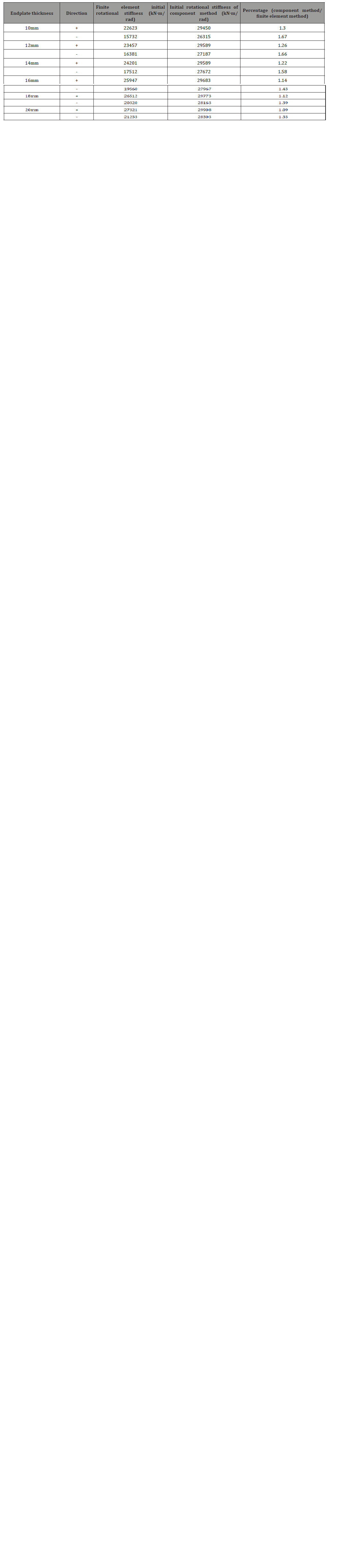
Table 5 shows that for beam-column composite nodes with weak-axis end plates considering the floor slab effect, the errors between the finite element method and the component method are relatively large, ranging from 33% to 67%, when the node is under positive bending moment. When the bolt specification is M20 and the end plate thickness is 16mm to 20mm, the calculated initial rotational stiffness under negative bending moment is closer to that obtained from the finite element method. When the node is under negative bending moment, the errors between the finite element method and the component method are between 9% and 30%.
Conclusion
Through experimental research and finite element analysis on the initial rotational stiffness of end plate connection joints considering slab effects, the following conclusions can be drawn:
• The floor slab significantly increases the initial rotational stiffness of joints, with an increase ranging from 10% to 35% depending on the joint configuration.
• The end plate thickness and bolt diameter are key parameters affecting initial rotational stiffness. For joint configurations with floor slabs, when the end plate thickness increases from 16 mm to 20 mm, the initial rotational stiffness increase is approximately 15%. When the floor slab effect is not considered, the variation in initial rotational stiffness ranges from 8% to 28%.
• Based on the component method, a theoretical calculation model for the initial rotational stiffness of composite joints was established. The calculated results show good agreement with finite element analysis results, and the proposed theoretical calculation method can effectively predict the initial rotational stiffness considering the floor slab effect, with errors ranging from 5% to 19%, demonstrating its reliability.
• By comparing experimental results with finite element analysis and theoretical calculations, it can be concluded that the component method provides a reasonable approach for predicting joint behavior. For practical design purposes, considering EC3 and EC4 code provisions, the predicted initial rotational stiffness values show variations ranging from 9% to 30%, with better accuracy for end plate thicknesses in the range of 10 mm to 14 mm, and slightly larger deviations for 16 mm to 20 mm thickness range.
Acknowledgment
Funding: This research was supported by the launch funding for doctoral research at Wuyi University (Grant No. BSQD2218); The Jiangmen Basic and Theoretical Science Research Science and Technology Program (Grant No. 2023JC01024); Scientific Research Cooperation Project of Jiangmen Science and Technology Special Commissioners (2025760001270008929); Graduate Education Innovation Program of Wuyi University (YJS-SFKC-23-08).
Conflict of Interest
No conflict of interest.
References
- Li ZQ, Sun GH, Yang WX (2022) Mechanical behavior and improvement measures of inclined extended end-plate moment connections. Building Science 38(07): 25-33 (In Chinese).
- Yuan HX, Gao JD, Du XX (2022) Experimental Study of the Structural Behavior of the Stainless-Steel End-Plate Minor-Axis Joint of an I-Section Column. Journal of Tianjin University 55(08): 839-847 (In Chinese).
- Zhu YF, Chen CH, Yao Y, et al. (2018) Dynamic increase factor for progressive collapse analysis of semi-rigid steel frames. Steel and Composite Structures 28(2): 209-221.
- Elkady A (2022) Response characteristics of flush end-plate connections. Engineering Structures 269: 114856.
- Ma Kang, Ye Xihao, Zhao Yang, Yu Haifeng, Li Jiancheng (2021) Influence of composite slab on seismic performance of prefabricated steel frame joints. Journal of Hebei University of Science and Technology 42(05): 535-542 (In Chinese).
- Wang YD, Koetaka, Chan YJ, Iathong (2020) Elasto-plastic behavior of weak-panel beam-column joints with RC slabs under bidirectional loading. Journal of Constructional Steel Research 168.105880.1-105880.14.
- Haghighat A, Heydarian NA, Sharbatdar MK (2017) Evaluation of new composite rigid joint under cyclic loading and its effect on one floor composite frame. Journal of Structural and Construction Engineering 4(2): 85-105.
- Gil B, Goñi R, Bayo E (2013) Experimental and numerical validation of a new design for three-dimensional semi-rigid composite joints. Engineering Structures 48: 55-69.
- Amsyar F, Tan CS, Sulaiman A, et al. (2023) Semi-rigid composite beam-to-column joints for cold-formed steel frames: Experimental and numerical study. International Journal of Steel Structures 23(4): 974-992.
- Keikha H, Mofid M (2018) Seismic performance evaluation of a novel bolted flush end-plate beam splice connection. Proceedings of the Institution of Civil Engineers - Structures and Buildings 173(2): 1-48.
- Rodrigues MC, de Andrade SA, de Lima LR, Pedro CG da S Vellasco, Fernando B Ramires (2017) Experimental assessment of the composite joints shear connector component. Journal of Constructional Steel Research 132: 203-216.
- AISC-341-05 (2005) Recommended provisions for structural steel buildings [S]. American Institute of Steel Construction: INC, March 9, 2005.
- Deutsches Institut für Normung (2005) Eurocode 3: Design of steel structures, Part 1-8: Design of joints: BS EN 1993-1-8. London: British Standards Institution.
- Committee Europeen de Normalisation (1994) Eurocode No. 4: Design of composite steel and concrete structures - Part 1.1. Berlin: Deutsches Institut für Normung.
-

This work is licensed under a Creative Commons Attribution-NonCommercial 4.0 International License.