 Research Article
Performance and Design Optimization of Solar Powered Stirling Engine Using Genetic Algorithm
Osama Mohammed Elmardi Suleiman1*, Abdalazeem Adam2 and Tagelsir Hassan3
1Department of Mechanical Engineering, Nile Valley University, Sudan
2Department of Mechanical Engineering, Karary University, Sudan
3Department of Mechanical Engineering, Omdurman Islamic University, Sudan
Osama Mohammed Elmardi Suleiman, Department of Mechanical Engineering, Nile Valley University, Atbara, River Nile, Sudan.
Received Date: August 20, 2018; Published Date: September 06, 2018
Abstract
The aim of this work is to optimize the design and performance of solar powered γ Stirling engine based on genetic algorithm (GA). A second-order mathematical model which includes thermal losses coupled with genetic algorithm GA has been developed and used to find the best values for different design variables. The physical geometry of the γ Stirling engine has been used as an objective variable in the genetic algorithm GA to determine the optimal parameters. The design geometry of the heat exchanger was considered to be the objective variable. The heater slots height, heater effective length, cooler slots height, cooler effective length, re-generator foil unrolled length and re-generator effective length are assumed to be the objective variables. Also, three different types of working fluids have been used in the model simulation to investigate the effect of the different working fluid on the engine performance. The comparison between the results obtained from the simulation by using the original parameters and the results from the optimized parameters when the engine was powered by solar energy; the higher temperature was 923 K applied to the working fluid when the air, helium, and hydrogen were used as working fluid. The engine power increases from 140.58 watts to 228.54 watts, and it is enhanced by approximately 50%, when the heating temperature is 923 K and the air is used as working fluid. The result showed that the working temperature is one of the most important parameters; because the output power increases by increasing of the hot side temperature.
Keywords: Low temperature differential (LTD) Stirling engine; Genetic algorithm (GA); Coolers and heat pumps (CHP)
Introduction
Energy production through clean and green sources has found great interest recently, because the proportion of high oil prices and fuel oil have caused severe problems to the environment. Researchers consider renewable energy resources as the best alternative to the trendy energy sources, these source of renewable energy it can be used as an input energy source for heat the Stirling engines [1,2]. Stirling engines are mechanical devices theoretically working on the Stirling cycle and using a compressible fluid, such as air, helium, hydrogen and nitrogen. They can also use vapors as working fluid [3,4]. `Stirling engines have been used in various types of applications such as energy converters for Stirling/Dish, coolers, and heat pumps, residential CHP etc. In recent years they were applied in the renewable energy fields. The Stirling engine systems design and development has been signified for combined heat and power systems [5]. In fact, the Stirling engines are friend to the environment than the internal combustion engines so that it found great interest [6]. Developing Stirling engine and improving its performance for getting its highest thermal power have been the concern of some researchers around the world [4,7]. Principally to design an engine, firstly has to find a set of parameters based on experiences and secondly optimize the design for other parameters so as to improve the performance [8]. A lot of parameters like power piston and displacer geometries, heat exchanger geometries, temperatures, pressure, engine working frequency, have direct effect on the engine output power and efficiency and hence, they complicate the design procedure [5]. To understand the working fluid thermodynamic behavior of Stirling engines, there are a lot of techniques for Stirling cycle analysis. These techniques are categorized from zero to fourth order analysis [9-11]. RGJESh Arora et al. [12] optimized power output, overall thermal efficiency and thermo-economic function of solar powered Stirling heat engine with regenerative heat losses, conducting thermal bridging losses using evolutionary algorithm based on second version of nondominated sorting genetic algorithm (NSGA-II). Mohammad H. Ahmadi et al. [13] developed finite time thermodynamic analysis based on external irreversibility while internal irreversibility such as friction, entropy generation, and pressure drop were not considered. The finite-time thermodynamics have introduced to optimize the performance of a solar powered Stirling engine by Chen et al. [14]. The genetic algorithm was used to obtain the maximum output power of a Stirling engine by determining the thermal efficiency. Mahkamov et al. [15] have presented a mathematical model of the (LTD) Stirling engine which is used for the engine mechanical losses and the working hydraulic process and heat losses. The effect of irreversibility on the engine performance and heat losses was studied by Hirata [16] which was obtained the optimal performance and design parameters for maximum power and efficiency.
A lot of researchers studied the genetic algorithm to optimize the performance of Stirling engines. However, in this article the Genetic algorithm (GA) code coupled to the second-order mathematical model accounting for heat and mechanical loss is presented to optimize the moderate temperature differential Stirling engine. The purpose of the article is to determine the optimal design parameters of moderate temperature differential gamma type Stirling engine.
System Description
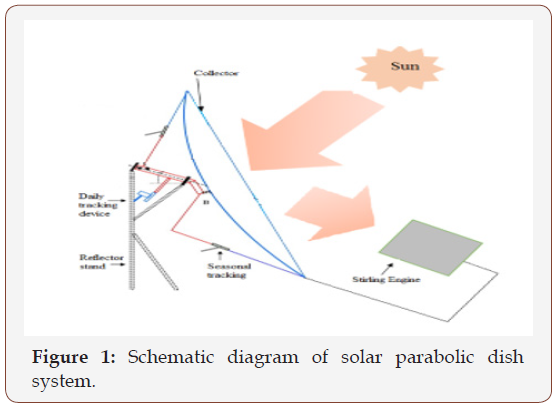
A solar powered γ Stirling engine is illustrated in Figure 1. It includes mirrors arranged in a parabolic mode to form a dish collector and thermal absorber on the focal point where collector collects all the solar radiations. A cavity absorber is created at the focal point which transfers collected solar energy to the working gas in engine’s displacer hot end. The solar dish is installed with a sun tracker which tracks the sun in order to have maximum solar energy transfer to the engine when the sun moves during day time as illustrated in Figure 1.
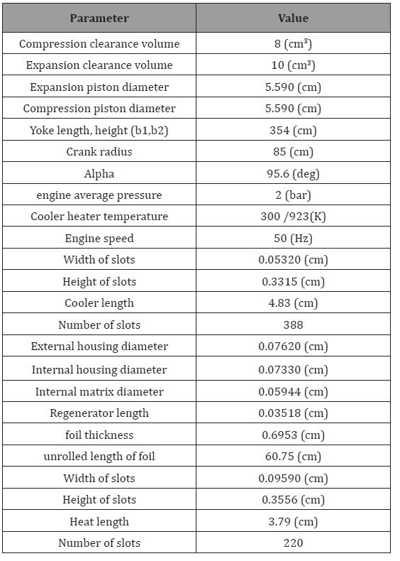
Gamma Stirling engine is one of the Stirling heat engine types, it consists of compression piston and expansion piston, and conventional heat exchangers: cooler, regenerator, and heater. The exchanger and the engine pistons are connected together, as shown in Figure 2. The engine used can be powered by any source of energy (combustion energy, solar energy, etc.). One of the pistons converts gas pressure into mechanical power, while the other piston is used to move gas between hot and cold spaces. This was analyzed by Urieli [17] and obtained good result. By using of an adiabatic and simple method, the engine presents an excellent theoretical efficiency. Table 1 below shows the engine geometry which is defined according to the direct measurements of few parts of the engine. These data can be used as input data in the simulations and to hypothesis regarding the inaccessible parts. These data remain constant for every simulation.
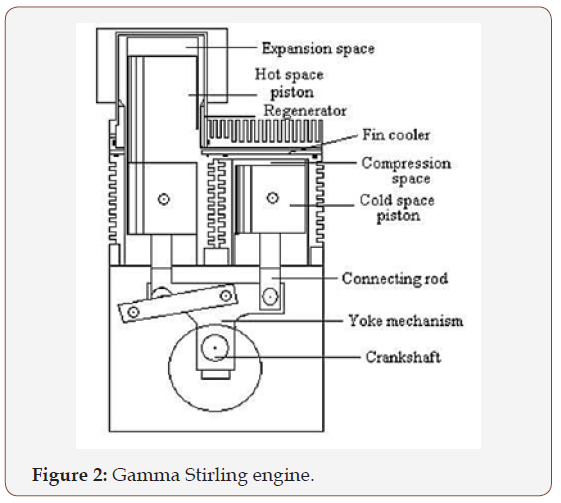
Table 1: Operating parameters of the engine geometry.
Thermodynamic Analysis
The Stirling engine mathematical model is used to describe the working process inside the engine. The gas flow inside the engine was divided into five control volumes and the mass and energy conservation equations are applied to each of the control volumes. The engine operation was described by system of equations which also includes the ideal gas state equation [18]. Urieli [17] developed the second-order mathematical model of Stirling engines which is modified by dividing the regenerator into several control volumes. The division of the engine’s gas flow into control volumes is shown in Figure 3. The assumptions in this model are as follows:
• In each control volume the pressure derivative is the same.
• There are no gas leakages through sealing rings of the displacer rod and of the power pistons.
• The working gas is considered as a perfect gas in each control volume.
• The walls of the power piston and displacer cylinders are thermally insulated.
• The engine operates at steady state conditions.
Table 1: 8 pairs of insoles sample with different softness selected.
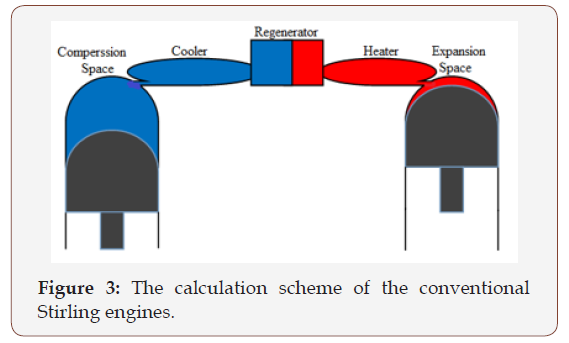
Pressure in the engine can be found as:

where P is the pressure (pa); M is total mass of the working gas in the engine (kg); R is the gas constant (J/kg. k); Vi is the control volumes (m3); Ti is the gas temperature in control volumes (K); i = c, k, r, h, e.
Pressure variation can be calculated by:

Mass equation

Mass variation
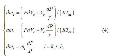
The gas mass flow rate between the control volumes can be defined as follows:
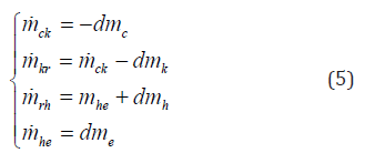
The conditional temperature of the gas between the compression, cooler space and the heater expansion space are defined as follows:

where  , Tck is mass flow rate and temperature between the
compression and the cooler spaces (kg/s) , (K), respectively; Tc is
the temperature of the gas in the compression space (K); Tk is the
temperature of the cooler space (K);
  , The is mass flow rate and
temperature between the heater and the expansion spaces (kg/s)
, (K), respectively; Th is the temperature of the gas in the heater
space (K); Te is the temperature of the expansion space (K)
The energy conservation equations for the cooler, regenerator and heater spaces, respectively, can be expressed by the following equations:
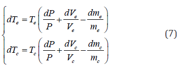
where Qk, Qr and Qh are the heat flow rates in the cooler, the regenerator and the heater (W), respectively.
The work done on or by the working gas inside the compression and the expansion space can be calculated as:
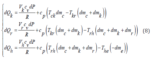
where Qk, Qr and Qh are the heat flow rates in the cooler, the regenerator and the heater (W), respectively.
The work done on or by the working gas inside the compression and the expansion space can be calculated as:

where Wc and We are works done on or by the gas in the compression and expansion spaces, respectively (J).
Non-ideal heat exchangers
For the systems which have non-ideal regenerator, when the working gas flows through the cooler to the heater, on exit from the regenerator it will have a temperature comparatively lower than that of the heater. This will result in more heat being supplied externally over the cycle by the heater in increasing the temperature of the gas to that of heater. Likewise, when the working gas flows through the heater to the cooler, then an extra cooling load will be burdened on the cooler [19] as follows:

Non-ideal regeneration
The effectiveness of the regenerator is given starting from the equation below:

where NTU values can be found in terms of the Stanton number by:

where ST is Stanton number and it can be found from the average Reynolds number determined over one cycle.
Pumping work loss
While the working gas flow between the cooler, regenerator, and heater volumes the fluid friction will result in pressure drop between the variable volumes. This reduces the output power of the engine and it’s known as pumping work losses [20]. Pressure drop is evaluated from:

where fr is the friction coefficient and can be calculated from Reynolds for the specific fluid conditions at a given time for specific heat exchanger; μ, U, V, dh, and A denote the working gas dynamic viscosity (Pa.s), the fluid mean bulk velocity (m/s), the void volume (m3), the hydraulic diameter (m) and the internal free flow area (m2), respectively.
The thermal efficiency of the Ideal Adiabatic cycle is given in terms of the energy values accumulated at the end of the cycle by:

The thermal efficiency of the non-ideal engine is given by:

Optimization Modeling
Introduction to the genetic algorithms
Genetics algorithm is a random optimization method based on the technique of natural selection for survival in order to get the optimal results [21]. The continuous GA is applied in this work for the quantitative restriction and the reduction of the computing time [22].
Definition of the objective function
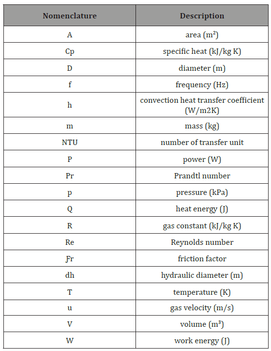
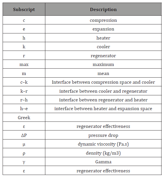
The heat exchangers of moderate and high-temperature differential Stirling engines, namely a heater, a cooler and a regenerator should be carefully designed because these greatly affect the engine performance. Any deviation from optimal design dimensions, specially of the regenerator, may result in a significant drop in the engine’s output power [23]. In this work various original engine operational and design parameters are accepted to be fixed as constant values. There are only six engine designs parameters are defined as variables. These are heater slots height, heater effective length, cooler slots height, cooler effective length, regenerator foil unrolled length and regenerator effective length as illustrated in Table 2:

Table 2

The indicated power is used as the objective function and is calculated using the developed second-order mathematical model for Stirling engines:

Genetic algorithm procedure
The guessed initial chromosome in the initial population which is created by using the random procedure has no effect on the convergence of the solution, of the GA. The generated initial population is in the matrix formation of various chromosomes. But the size of the population affects the convergence in the optimization procedure. To operate GA the number of chromosomes is better to be between 30 and 100 [24]. The number of chromosomes in a generation of 30 is used in this work. The chromosome value which is the indicated power is evaluated by the fitness function for locating in the value map of each generation [25].
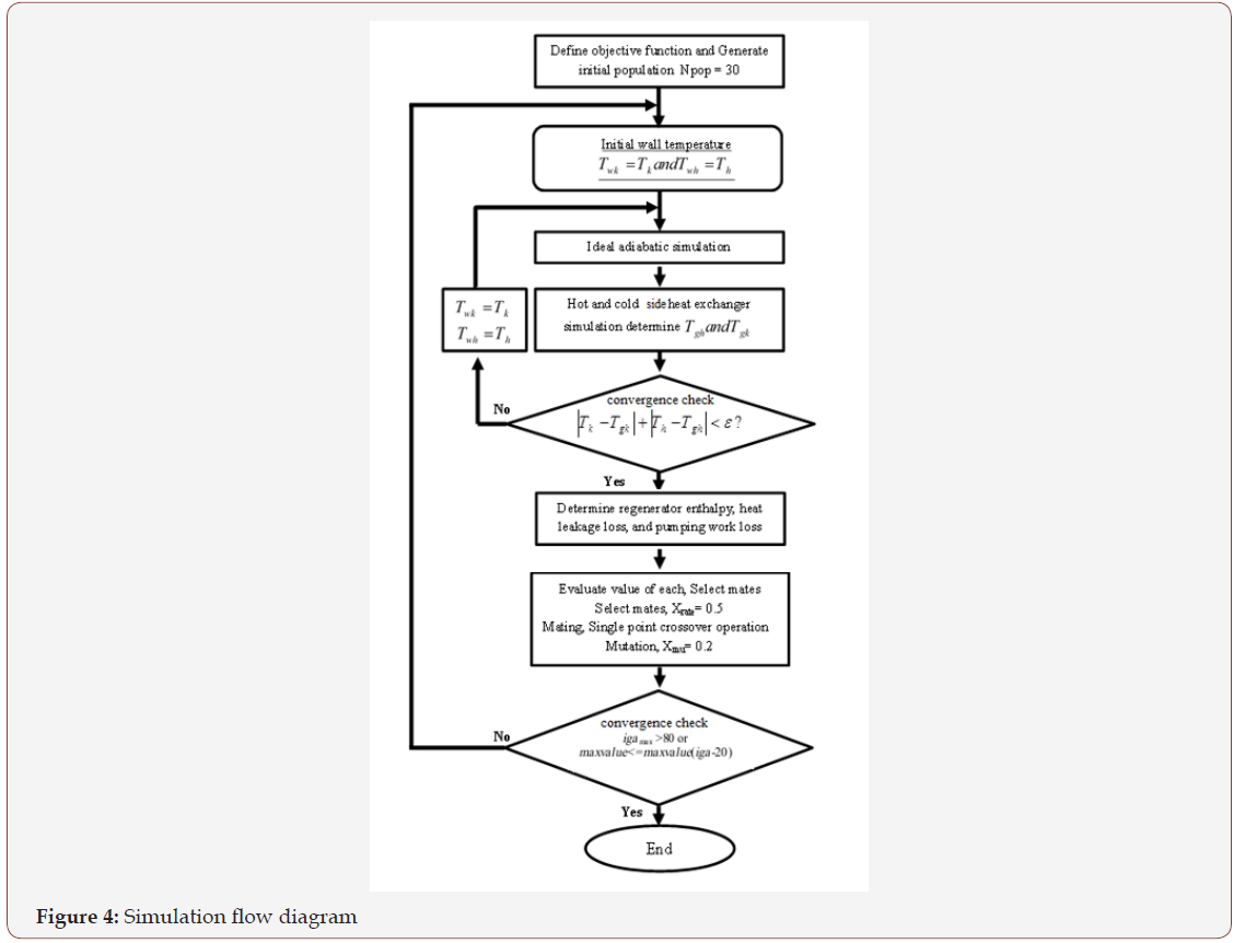
To determine the survived chromosomes for the next generation the fitness value of each chromosome is put in descending order. After that the number of survived chromosomes is found by the selection rate of 0.5, Then single point crossover is used for the mating process, and the fittest chromosomes of the ranking are randomly selected to be the parents for the reproduction operation, The mutation operator of rate 0.2 is used as a tool to avoid finding only the local solution, and finally, the new generation is produced and the population of new design parameters in this generation is then evaluated by the developed thermodynamic model and the fitness function is checked for the ranking until the solution found satisfying the termination condition[15, 22]. Figure 4 below shows the simulation flow diagram of GA.
Results and Discussion
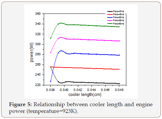
In order to evaluate the effect of the heat exchanger, engine operating frequency (Freq), and the hot source temperature (TH) on the performance of the Stirling engine, all the parameter was kept constant except the cooler length (lk), its vary between (0.038- 0.048) cm, the regenerator length from (0.005-0.04) cm, the heater length from (0.035-0.075) cm, the operating frequency from (40- 60) Hz, and the hot side temperature from (723-1023) K the result obtained are as follows
The effect of the cooler, regenerator, and the heater on the output power of the engine is illustrated in Figures 5-7. It’s clear from Figure 5. The output power increases and reaches its maximum value when the cooler length gets the value between (0.038-0.04) cm and after that it starts decreasing. Figure 6 Shows that the output power reaches its maximum value at the beginning when the regenerator length is small and then starts decreasing. The best value of the output power is obtained when the regenerator length reaches a value between (0.005-0.01) cm. Figure 7 illustrates that the output power approaches the high value when the heater length reaches a value between (0.036-0.04) cm and then starts to decrease. It can be seen from Figure 8 that the output power increases by the increase of the hot side temperature and reaches its maximum value at 973K, and then starts decreasing.
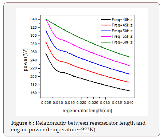
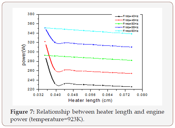
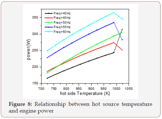
The optimal value of output power, and thermal efficiency are obtained from implementing evolutionary algorithm based on genetic algorithm (GA). The algorithm was coupled to the secondorder mathematical model. The engine was powered by solar energy and the high temperature was 1023 K which is applied to three different types of working fluid air, helium, and hydrogen respectively. When the air was used as working gas and the hot side temperature was 923 K the output power was 290.06 watt for adiabatic analysis and 228.5 watts for simple analysis. When the helium and the hydrogen were used at same operating condition with air the obtained power output were 275.4 and 290.06 watts for adiabatic analysis and 234.5 and 268.8 watts for simple analysis respectively. Comparison between the results obtained from the simulation by using the original parameters and the result from the optimal parameters are shown in Table 3.
Table 3: The ideal adiabatic power and the actual power.

Because of the instability of the solar heat energy during the day time the solar collector provides 1023 K as maximum temperature and 723 K as minimum temperature. The output power and the thermal efficiency get increase when the applied temperature increased and vice versa. Figure 9 & 10 illustrate the power output when the air was used as working fluid in temperature range (723-923) K. The actual power output means the power obtained from the simple analysis. They show that the thermal power and efficiency are increased by increasing the hot side temperature and vice versa.
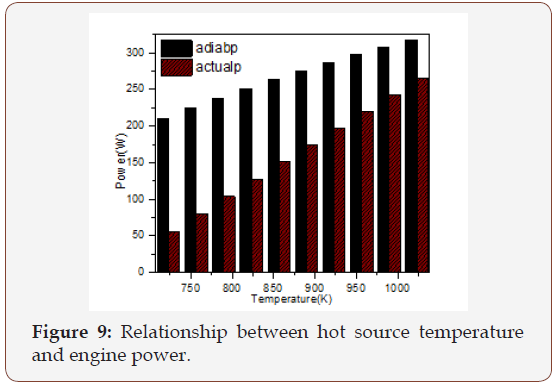
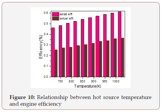
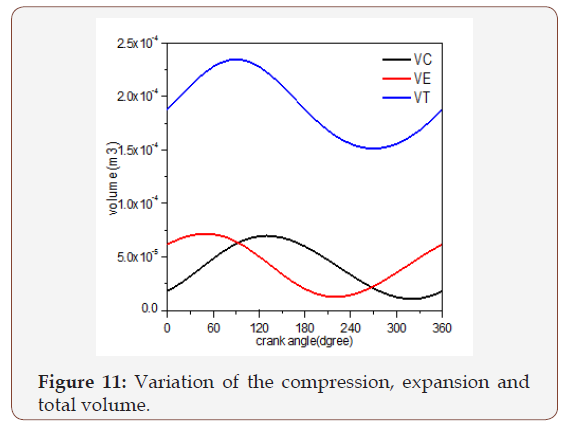
Figure 11 illustrates the variation of the compression, expansion and total volume as a function of the crank angle. The compression volume reaches its maximum value when the cycle has not started yet, because the flow direction of the working fluid flowing from compression space to the expansion space. Starting in the compression space, the working fluid is pressed through the cooler, the regenerator and the heater to the expansion space, successively. As the total volume Vt increases, the volume of the compression space Vc increases too, whereas the volume of the expansion space Ve decreases. After the working fluid was expanded in the expansion space, the flow moves back to the compression space.
The thermal energy transferred and the total work output over an ideal adiabatic cycle is illustrated in Figure 12. The energy transferred to cooler or to the heater is lower than the maximum heat transferred to and from the regenerator matrix. It is clear from the Figure 12 that the energy variation during the operation changes when the optimal data were applied to the system specially in the heater and regenerator. As a result of that the system provides better work output with respect to original engine geometry where the air was the working gas. Figure 13 shows the energy variation in the compression and expansion space obtained during the cycle as a function of the crank angle.
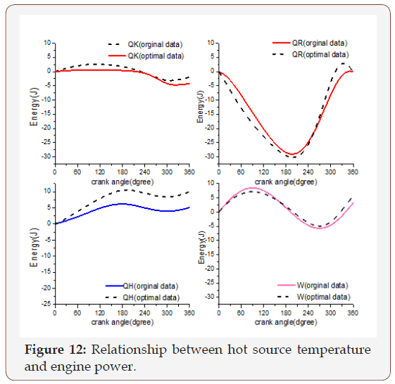
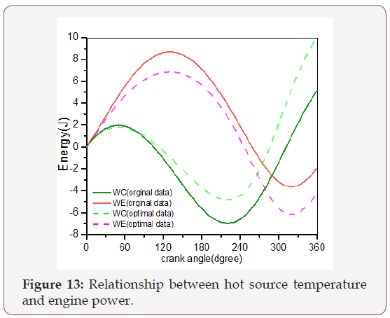
Figure 14 shows the working gas temperature in the compression and expansion spaces during the cycle while a mean effective temperature for the working gas was calculated. Also, the same figure showed the temperature variation in the expansion space and compression space. As illustrated when the optimal value was applied to the system, the temperature variation curve is varying in the temperature range of (235-279.5 K) on the cold side and from (785.3-938.4K) in the hot side. This makes the engine work more stable.
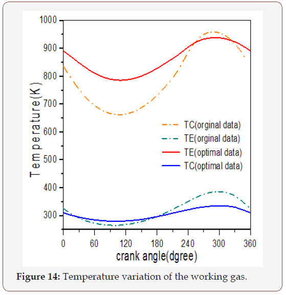
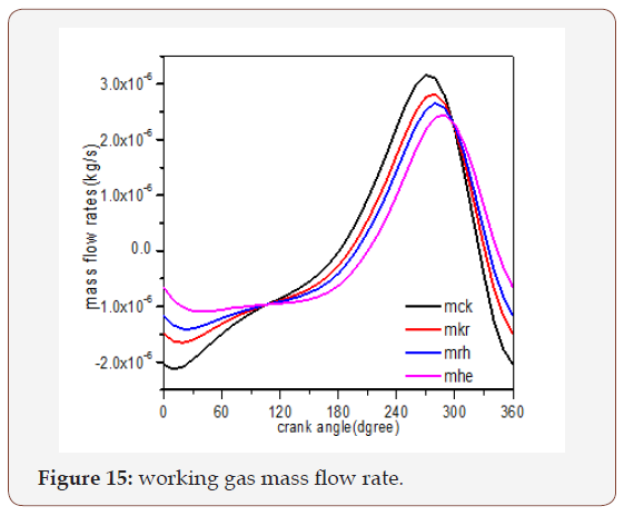
Figure 15 shows the mass flow rate variation in various spaces with crank angle the figure illustrate that the variation amplitude of flow rates is greater in the cold space. The positive flow rate period is more important than the negative flow rate; and there are values of the phase for which all the flow rates are equal. This phenomenon occurs at the time of each extreme of pressure.
Figure 16 illustrates pressure variation in the expansion and compression space of the engine and the two pressure waveforms are nearly in phase, which backing low pressure losses in the heat exchangers. Furthermore, it is observed that the maximum pressure is at 290° for both analyses.
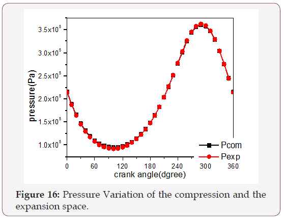
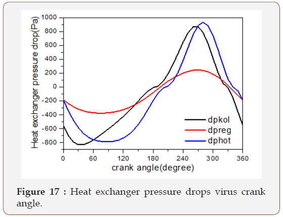
Figure 17 shows the pressure reduction of cooler, regenerator and heater on the Stirling engine. Note the relative magnitude of the regenerator pressure drop with respect to those of the heater and cooler. In the beginning, the pressure drop in the cooler start with -200Pa and then going down until it reaches -800Pa at 90º and starts to increase until it reaches its maximum value at 290°. But the variation in the regenerator is more stable, it is varying between (-370-245) Pa. The variation in the heater is similar to the variation in the cooler. This process cause losses in the output power named by pumping work losses.
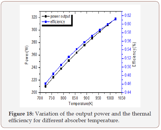
Figure 18 shows the variation of the output power and the thermal efficiency for different absorber temperature. Table 4 shows the optimal values obtained from the simulation results.
Table 4: The optimal values obtained from the simulation results.

Conclusion
In this work, the developed second-order mathematical model of the Stirling engine coupled with the genetic algorithm (GA) optimization model was used in order to study the performance and design optimization of the Stirling engine. In the simulation, the Stirling thermodynamic cycle heat transfer limitations and pumping losses was taken into account. Results show that a set of design parameters for the engine were obtained which have strongly effect on the engine performance. The comparison between the results obtained from the simulation by using the original parameters and the result from the parameters when the engine was powered by external energy. The high temperature was 923 K applied to the working fluid and the total output power when the air, helium, and hydrogen used as working fluid. The result showed that he working temperature is important, for Stirling engine system. The increase of the input source temperature is very important, the high temperature gives better system performance. The change of the regenerator dimension was optimized the engine output power. When the optimal design parameters are introduced in the model, the engine power increases from 140.58(watts) to 228.54(watts). Engine power is enhanced by approximately 50%, when the heating temperature is 923 (K) and the air is used as working fluid.
Acknowledgement
The author would like to acknowledge with deep thanks and profound gratitude Mr. Osama Mahmoud Mohammed Ali of Daniya Center for Publishing and Printing Services, Atbara, who spent many hours in editing, re – editing of the manuscript in compliance with the standard format of Academic Journal of Engineering Sciences.
References
- Giuseppe Marco Tina, Salvina Gagliano (2011) Probabilistic modelling of hybrid solar/wind power system with solar tracking system. Renewable Energy 36(6): 1719-1727.
- Panayiotou Gregoris, Kalogirou Soteris, Tassou Sawas (2012) Design and simulation of a PV and PV Wind standalone energy system to power a household application. Renew Energy 37(1): 355-363.
- Iskander Tlili, Musmar A Saed (2013) Thermodynamic evaluation of a second order simulation for Yoke Ross Stirling engine. Energy Convers Manage 68: 149-160.
- Hadi Hosseinzade, Hoseyn Sayyaadi (2015) CAFS: The Combined Adiabatic-Finite Speed thermal model for simulation and optimization of Stirling engines. Energy Conversion and Management 91: 32-53.
- Hooshang M, R Askari Moghadam, S Alizadeh Nia, M Tale Masouleh (2015) Optimization of Stirling engine design parameters using neural networks. Renewable Energy 74: 855-866.
- Kongtragool Bancha, Wongwises Somchai (2003) A review of solarpowered Stirling engines and low temperature differential Stirling engines. Renew Sustain Energy Rev 7(2): 131-154.
- Mohammad Hussein Ahmadi, Mohammad Ali Ahmadi, Adel Mellit, Fathollah Pourfayaz, Michel Feidt (2016) Thermodynamic analysis and multi objective optimization of performance of solar dish Stirling engine by the centrality of entransy and entropy generation. International Journal of Electrical Power & Energy Systems 78: 88-95.
- Yaqia Li, Yalinga He, Wang Weiwei (2011) optimization of solar-powered Stirling heat engine with finite-time thermodynamics. Renew Energy 36(1): 421-427.
- Rodger D, W Scottt, T Roy (2004) Review of Computational Stirling Analysis Methods, in 2nd International Energy Conversion Engineering Conference. American Institute of Aeronautics and Astronautics.
- Cheng CH, Ying Yu J (2010) Numerical model for predicting thermodynamic cycle and thermal efficiency of a beta-type Stirling engine with rhombic-drive mechanism. Renew Energy 35(11): 2590- 2601.
- Makhkamov K, DD (2003) Three-dimensional CFD modeling of a Stirling engine. In: Stirling Engine in Conference. Rome, Italy
- Arora RGJESh, SC Kaushik, Raj Kumar, Ranjana Arora (2016) Multiobjective thermo-economic optimization of solar parabolic dish Stirling heat engine with regenerative losses using NSGA-II and decision making. International Journal of Electrical Power & Energy Systems 74: 25-35.
- Mohammad H Ahmadi, Mohammad Ali Ahamdi, Fathollah Pourfayaz, Mokhtar Bidi, Michel Feidt et al. (2016) Optimization of powered Stirling heat engine with finite speed thermodynamics. Energy Conversion and Management 108: 96-105.
- Chen CL, Ho CE, Yau HT (2012) Performance analysis and optimization of a solar powered Stirling engine with heat transfer considerations. Energies, 5: 3573-3585.
- Kraitong Kwanchai, Khamid Mahkamov (2011) Optimization of low temperature difference solar Stirling engines using genetic algorithm. P: 3945-3952.
- Koichi Hirata (2003) Mechanical loss reduction of a 100 W Class Stirling engine. International Maritime Research Institute p: 1-6.
- Urieli Israel, Berchowitz DM (1984) Stirling cycle engine analysis. (A Hilger Ltd).
- Timoumi Youssef, Iskander Tlili, Sassi Ben Nasrallah (2008) Design and performance optimization of GPU-3 Stirling engines. Energy 33(7): 1100-1114.
- Ana C Ferreira, Ricardo F Oliveira, Manuel L Nunes, Luis B Martins, Senhorinha F Teixeira (2014) Modelling and Cost Estimation of Stirling Engine for CHP Applications. P. 21-29.
- Strauss JM, RT Dobson (2010) Evaluation of a second order simulation for Sterling engine design and optimisation. Energy in Southern Africa 21(2): 17-29.
- DE Goldberg (1989) Genetic Algorithms in Search, Optimization & Machine Learning. Addison-Wesley Publishing Company, USA.
- RL Haupt, SE Haupt (2004) Practical Genetic Algorithms. (2nd edn), USA, John Wiley & Sons, USA, pp. 1-251.
- Jafar Zarinchang, A Yarmahmoudi (2009) Optimization of Thermal Components in a Stirling Engine. 4(1).
- AMS Zalzala, PJ Fleming (1997) Genetic Algorithms in Engineering Systems. UK, The Institution of Electrical Engineers, P: 1-254.
- Shopova EG, NG Vaklieva Bancheva (2006) BASIC-A genetic algorithm for engineering problems solution. Computers & Chemical Engineering, 30(8): 1293-1309.
-
Osama Mohammed E S, Abdalazeem A, Tagelsir H. Performance and Design Optimization of Solar Powered Stirling Engine Using Genetic Algorithm. Glob J Eng Sci. 1(1): 2018. GJES.MS.ID.000501.
-
Low temperature differential (LTD) Stirling engine, Genetic algorithm (GA), Coolers and heat pumps (CHP), Genetic algorithm, Gamma Stirling engine, Conventional Stirling engine, Non ideal heat exchangers, Objective function, Simulation flow, Thermodynamic analysis, Solar parabolic dish system, Optimal parameters, Working fluid, Thermal efficiency, Thermo economic function, Evolutionary algorithm, Non dominated sorting genetic algorithm (NSGA-II), Hydraulic process, Power pistons, Ideal adiabatic numerical formulation
-

This work is licensed under a Creative Commons Attribution-NonCommercial 4.0 International License.


