 Research Article
Numerical Simulation of Phase Transformation and Reorientation in Single Crystalline Shape Memory Alloys
JJ Zhu1*, NG Liang2, M Cai3, KM Liew4 and WM Huang5
1School of Civil Engineering and Architecture, Wuyi University, China
2LNM Institute of Mechanics, Chinese Academy of Sciences, Beijing, China
3Department of Engineering Technology, University of Houston, USA
4Department of Architecture and Civil Engineering, City University of Hong Kong, Kowloon, Hong Kong
5School of Mechanical and Aerospace Engineering, Nanyang Technological University, Singapore
JJ Zhu, School of Civil Engineering and Architecture, Wuyi University, China.
Received Date: September 08, 2018; Published Date: September 24, 2018
Abstract
In our previous paper [1], a constitutive model was developed for the stress-induced martensitic transformation and reorientation in single crystalline shape memory alloys. The critical condition and evolution equation for the phase transformation and reorientation were proposed. In this paper, the model proposed in our previous paper [1] is applied to simulate the behavior of stress-induced phase transformation in a CuZnAl single crystal and reorientation between CuAlNi martensite lattice correspondence variants. It is found out that the prediction results are consistent with the experimental data reported in the literature.
Keywords: Phase transformation; Thermomechanical processes; Microstructure; Constitutive behavior; Shape memory alloy
Introduction
Shape memory alloys have been widely used in mechanical, automotive, aerospace, nuclear, dental, medical and domestic appliance industries [2-5]. In order to provide a robust computation tool for engineers, much attention has been devoted to model the mechanical behavior of shape memory alloys [6-41]. However, the sophisticated thermo-mechanical behaviors under various loading conditions make the modeling a complex task. Under external mechanical/thermal loading, shape memory alloys exhibit some unique phenomena of practical interest, such as, superelastic behavior and shape memory effect. Those phenomena are due to the phase transformation and reorientation at microscopic level. Basic transition process comprises of forward transformation from austenite to martensite habit plane variant, reverse transformation from martensite habit plane variant to austenite, and reorientation among martensite lattice correspondence variants. Experimental studies on phase transformation, e.g. [42,43] and reorientation, e.g. [44] of single crystalline shape memory alloys were reported.
In our previous paper [1], a 3-D thermodynamic model for constitutive behavior of single crystalline shape memory alloys was developed. The model is based on the fact that martensite lattice correspondence variants are energy potential wells. Internal interaction energy among austenite and martensite variants is estimated by generalized Mori-Tanaka theory. We also derived the thermodynamic driving forces corresponding to the forward/ reverse phase transformation and reorientation, and the critical condition and the evolution equation for phase transition and reorientation. Moreover, the complex interior hysteresis loop is presented by the jump of critical thermodynamic driving force. In this paper, the model proposed in our previous paper [1] is used to investigate the behaviors of both stress-induced and thermally-induced phase transformation in a CuZnAl single crystal and martensite reorientation between CuAlNi martensite lattice correspondence variants.
Phase Transformation
Experimental data of forward and reverse martensitic transformations of some single crystalline shape memory alloys are available in the literature. For example, the uniaxial tensile tests of CuZnAl single crystals (transformation from DO3 austenite to 18R martensite upon straining) were reported [42,43]. It was assumed that only one martensite habit plane variant was induced in this process. Note that the induced martensite habit plane variant is the one in favor by the applied actual stress state. In this material, the number of habit plane variant, H=24. Each habit plane variant is a lattice correspondence variant. Thus, the transformation eigenstrain of the habit plane variant is the same as the eigenstrain of lattice correspondence variant and Eq. (57) in our previous paper [1] is valid. Eqs. (38) & (57) in our previous paper [1] yield

where

The first term of Eq. (2) stands for the interaction energy between martensite and austenite, while the second term for the interaction energy stored in the interface among martensite variants. Muller and Huo [43,45] have demonstrated that if two phases are mixed randomly, the number of interfaces per unit volume is proportional to z(1− z) , where z is the volume fraction of one phase. Figure 1 in Huo and Muller [43] shows that the relationship between the number of inter-phase and martensite volume fraction z is parabolic. The peak is located at z = 1/ 2 . If the elastic energy stored in per unit area of inter-phase is assumed to be a constant, the interaction energy can be expressed as , where A is a material constant. In trilinear model, for instance, [43,46], constant A is defined to be proportional to the slope of the second line, which corresponds to the phase transformation range (refer to Figure 2 in [46], Figures 3 & 4 in [43]). Thus, the mean elastic energy stored in the inter-phase at micro level is linked to the macro behavior by A . As pointed out in Seelecke [47], elastic distortion energy stored in the twinned plane is much less than the inter-phase (between austenite and martensite) energy stored in habit plane. If only the first term of the right side of Eq. (2) is reserved, one has

Substitution of Eq. (3) into Eq. (1) yields

Supposing that the tensile axis is along direction S, the applied stress may be expressed as

Here, we consider a particular case, assuming that the external load (mechanical and/or thermal load) has no apparent change during the phase transition, so that only one martensite habit plane variant (in the favorable orientation of the applied stress) is produced. From Eq. (4), the thermodynamic driving force corresponding to the active habit plane variant, which is in favor by the applied stress is reduced to

and the recoverable strain along the tensile axis is

According to our previous paper [1], the critical condition for the start of the phase transformation is

and the phase transformation evolution equation can be expressed as

Once the nucleation starts from the forward transformation, Πc− moves back to its maximum value (Π0− ) instantly. While when the reverse transformation starts, Πc+ returns to its minimum value ( Π0+). It is also reasonable to assume that Π0+ = Π0- = Π0.
In the tensile experiment on CuZnAl single crystals by Fu et al. [42], the intersection gauge area is 4.5×10⁻⁶m2 , the gauge length is 3.4×10⁻²m, the mass is 1.185×10⁻³ kg. If the International System of Units (SI) is adopted, vertical scale in figures of Fu et al. 42 should be divided by 4.5×10⁻⁶m2 and the horizontal scale should be divided by 28.7 m/kg. Based on the data in Fu et al. [42], we take MPa Π0= 0 for this particular sample. From Figure 5 of Fu et al. [42], one can obtain [Refer to page19 of [42] for details],

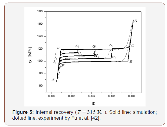
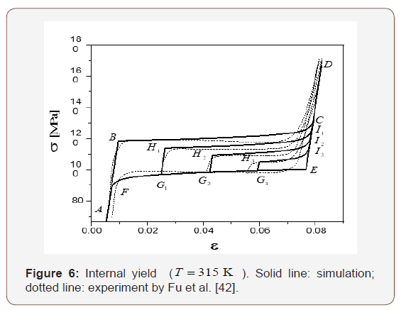
As shown in Eq. (4.3) of Fu et al. [42], the inside area of a full hysteresis loop is 2A. Assume that the stress at points B and E are σB and σE , respectively, in Figure 5 (so as in Figure 2 & 6), then

For simplicity, A can be directly obtained from Fu et al. [42] as

Δu and Δh may be determined by the hysteresis loops at different temperatures. For example, B in Figure 5 is the starting point of the forward transformation. Thus, we have Π = 0 and z0 =1 at point B . Substituting them into Eq. (6) yields

Two hysteresis loops at two different temperatures, T1 and T2 , can be obtained experimentally (as shown in Figure 2 of [42]). Thus,

where σ1 and σ2 are stresses for point B at temperature T1 and T2 . From Eqs. (15) and (16)

and


Using the data in Fu et al. [42] (refer to Figure 7 and Eq. (3.31) in [42] for details), we have

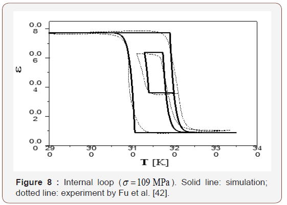
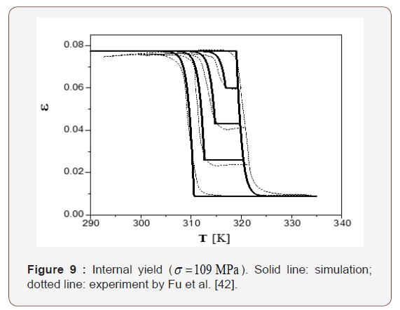
Note that (λ − A) is the parameter for hardening; in which λ > A stands for hardening, λ < A stands for softening and λ = A corresponding to a horizontal plateaus. All three cases are possible depending on the exact material and the loading/unloading conditions. We show horizontal plateaus in Figures 2,5 & 6 and small hardening in Figures 3,8 & 9 (also referring to page 5 of [42] for details]. We assume a low level of hardening (1% ) in our simulation for simplicity, i.e. (λ − A) = A×1%. Thus

We also introduce parameter μ to describe the “turn-up tail” behavior when the transformation nearly finishes, and make an adequate assumption μ = A×5% i.e.

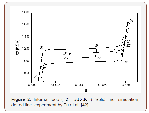
The CuZnAl single crystal exhibits superelastic behavior in the
isothermal process at T = 315 K in [42]. Three different types of
cyclic stress-strain curves were reported. The simulation of present
model against that experiment are plotted in Figures 2,5&6. As
shown in Figure 5, the whole material is austenite at point A . When
loaded to point B , the thermodynamic driving force Π reaches the
critical value Π0+ (= 0). Consequently, the forward transformation
starts. Loading from B to C , both Π and Πc+ increase and
 . The evolution of the forward phase transformation can
be determined by integrating Eq. (9). When loaded to point C ,
the whole material transforms into 100%martensite. The material
deforms elastically from C to Dduring loading and from Dto E
upon unloading. When unloaded to point E , the thermodynamic
driving force Π decreases to the critical value, Π0- (= 0), and the
reverse transformation starts. Eq. (9) is also employed for modeling
the evolution of the reverse phase transformation. Upon unloaded
to point F , the whole material transforms back to austenite. A-BC-
D-E-F-A is a complete forward-reverse transformation loop. In
another loading path A-B-G1-H1-I1-A, the forward transformation
starts upon loaded to B . Upon loading to point G1 only a part of
the material transforms into martensite. Unloading from G1 to H1
, because Πc−< Π < Πc+, the material deforms elastically (note
that during this process, Πc+ maintains its value as at point
G1).
When unloaded to point H1 the thermodynamic driving force Π
reaches the critical value, Π0- (= 0). Then the reverse transformation
starts. When unloaded to point I1, the whole material transforms
back to austenite. Thus, A-B-G1-H1-I1-A is an incomplete forwardreverse
transformation path. Similarly, loops of A-B-G2-H2-I2-A
and A-B-G3-H3-I3-A illustrate two incomplete forward-reverse
transformation paths. Points are practically lie on a diagonal line,
which corresponds to Π = 0 .
A-B-C-D-E-F-A in Figure 2 is a complete forward-reverse transformation loop. For the loop A-B-C-D-E-G1-H1-I1-D-E-F-A, the reverse transformation is not yet complete upon unloading to G1. The material deforms elastically upon loading from G1 to H1 ., and thermodynamic driving force Π reaches the critical value, Π0+ (= 0) at point H1 . Forward transformation restarts then after. Upon loading from H1 to I1 , the whole materials transform into martensite completely again. Note that upon the first loading from C to D and unloading from D to E , Πc+ maintains the same value as at point C . At point E , Πc+ reverses back to its minimum Π0+ (= 0) once reverse transformation starts. Upon unloading from E to G1 , Πc+ is unchanged while Πc- decreases with Π. Upon reloading from G1 to H10000, both Πc+ and Πc- are unaffected. Thus, Πc+ equals Π0+ (= 0) at point H1 (instead of that at point C ). At point H1 , once the forward transformation starts, Πc− goes back to the maximum Π0- (= 0) instead of the value at point G1 . Similar observations apply to the loops A-B-C-D-E-G2-H2-I2-D-E-F-A and A-B-C-D-E-G3-H3-I3- D-E-F-A.
In Figure 2, A-B-C-D-E-F-A is a complete forward-reverse transformation. In the loop of A-G-H-I-J-K-D-E-F-A, Π increases to Πc+ = Π0+(=0) upon loading to B . Thus, the forward transformation starts from point B . During loading from B to G , Πc+ increases at the same rate as that of Π in the evolution of forward transformation. The deformation is elastic during unloading from G to H and Πc+ remains the value as at point G . At point H , Π is reduced to Πc- = Π0-(=0). Thus, the reverse transformation starts and Πc+ reverses back to the minimum Πc- = Π0-(=0). Similar to the forward transformation, Πc− decreases from H to I at the same rate of Π in the evolution of the reverse transformation. Reloading from I to J , the material deforms elastically and Πc− maintains the value as at point I . At point J , Π increases to Πc+ = Π0+(=0). The forward transformation restarts and Πc− returns to the maximum Πc- = Π0-(=0). Upon loading to K , the whole material transforms into martensite again. The points B, J ,H, E lie on a diagonal line, which corresponds to Π = 0.
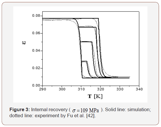
Temperature plays a critical role in mechanical response of shape memory alloys. Three different types of cyclic temperature vs. strain curves of a CuZnAl single crystal under a constant stress of σ = 109 MPa were reported in [42]. It was found that the material exhibits superelastic behavior under those loading conditions, and the effect of change in temperature on the transformation is equivalent to the change of stress. Equilibrium of σ and T is associated with a Clapeyron-like equation, which is analogous to the Clausius-Clapeyron equation. Differentiating Eq. (6) and keeping Π as a constant, one has

Both analytical result and experiment data of this case are shown in Figures 3,8 & 9. Comparing Figures 2,5&6 with Figures 3,8 & 9, we notice that the constant-stress process is similar to the constant-temperature process. However, in the constant-stress process, the prescribed stress must be large enough to ensure only one martensite variant is produced. Therefore, the associated deformation is always super elasticity.
According to Eq. (6), there are three parts included in the thermodynamic driving force Π for the forward (or reverse) transformation. The first is mechanical load device, the second is temperature load device, and the third is the stored energy. The sum of the first two is also called load device energy. It can be seen from Figures 2,3,5,6,8&9 that the variation of load device energy between the forward and the reverse transformation is about 1.5 MPa . The variation of stored energy is about 1.26 MPa . Both are of the same order of magnitude. Thus, the stored energy between austenite and martensite phase-interface cannot be ignored.
It appears that our simulation is very close to the measured behavior.
Reorientation
We now consider the reorientation between 2H martensite variants in a Cu-14.0wt%Al-3.9wt%Ni shape memory single crystal. Experimental data are taken from Abeyaratne et al. [44]. 2H martensite of CuAlNi has 6 corresponding variants and 24 habit plane variants [48-50]. Each habit plane variant consists of two twin-related lattice correspondence variants.
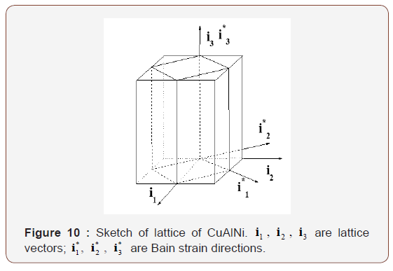
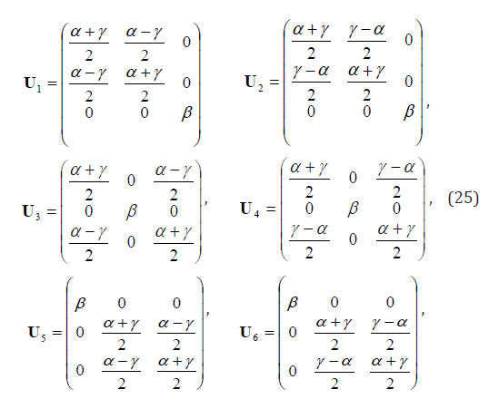
where α , β , γ have been measured by Otsuka and Shimizu [51] as

The corresponding Green strain is

According to Abeyaratne et al. [44], initially the single crystal is martensite variant 2. Stresses were applied along two orthogonal directions 1 S and 2 S , i.e.,

where θ is the angle between S1 and i1 . In the experiment, tw θ were chosen, namely, π/8(denoted by θ1) and π/4 (denoted by θ1 ). Thus, the applied stress may be expressed as

Variant 2 may transform into variants 1,3,4,5 or 6 upon stressing. The corresponding process variables are ζ21, ζ 23, ζ24 , ζ25, and ζ24, and their stoichiometric coefficients are
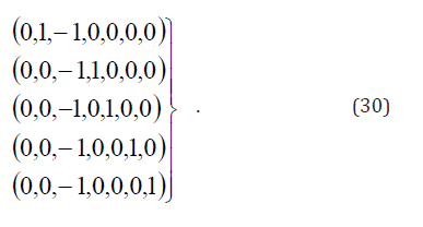
Only two martensite lattice correspondence variants were presented in [44]. The volume fraction of austenite, z,0 = 0 . In this case, Eq. (2) is reduced to

where is the volume fraction of one variant, while (1− z) is another.
Elastic energy stored in the twin-interface between the martensite lattice correspondence variants can be evaluated by the number of needle tips [44]. It was found that the density of needle tips terminated in transition layer is mainly dependent on the volume fraction of martensite lattice correspondence variant. Total transition layer energy can be written as [44]

where c1 and c2 are constants standing for two types of transition layers observed. Since there is no other difference between these two martensite lattice correspondence variants except for the orientation, c1 and c2 should be the same. If c1 = c2 , with the addition of a constant energy term, Eq. (32) may be rewritten as Bz(1− z) . Based on the non-local interaction theory, Rogers also concluded that the interaction energy between two martensite variants may be expressed by Bz(1− z) [52]. According to Abeyaratne et al. [44] onstant B is about 0.017MPa . From Figure 9 of [44], the variation of load device energy between reorientation and its reverse process is about 0.15MPa . Thus, transition layer energy is ignorable as compared with load device energy, i.e., Eq. (3) is an acceptable approximation for martensite variant reorientation.
Using Eq. (65) in our previous paper1 (or substituting Eq. (30) into Eq. (58) in our previous paper [1]) and ignoring interaction energy, the corresponding thermodynamic driving forces can be written as
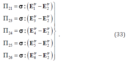
From Eqs. (25)-(29), we have
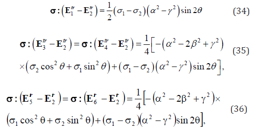
Thus,

Let

Hence,

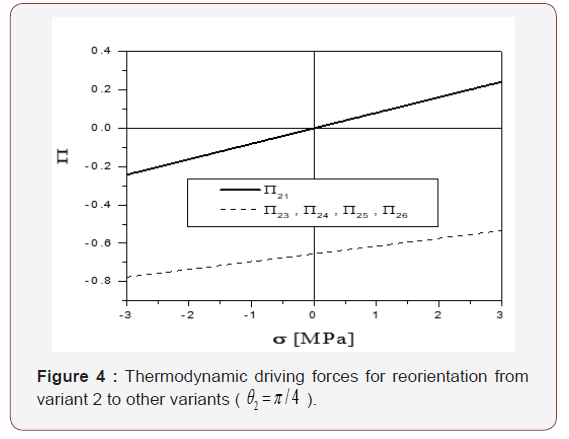
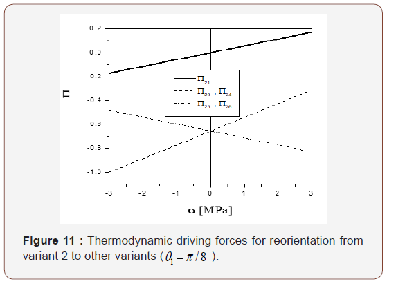
According to Abeyaratne et al. [44], σ1 +σ =10.7MPa , and −1.5 MPa ≤σ ≤1.5MPa . Substituting Eq. (26) into Eqs. (37)- (39) and assuming θ = Π/8 and , c = 5.35MPa the variation of the thermodynamic driving force against increases from -1.5 MPa to 1.5 MPa. As shown in Figure 11, Π21 is much larger than Π23 and Π24 . Hence, under the given loading condition described in [44], variant 2 has no other choice but transforms into variant 1.
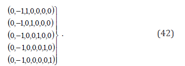
Upon further loading, variant 1 may transform to variants 2, 3, 4, 5 or 6. Introducing process variables ζ12 , ζ13 ,ζ21 , and ζ15 , their corresponding stoichiometric coefficients (ν0l ,ν1l,ν2l …ν6l) ( l = 2, 3, 4, 5, 6) are
The corresponding thermodynamic driving forces can be written as
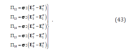
Eqs. (25)-(29) yield
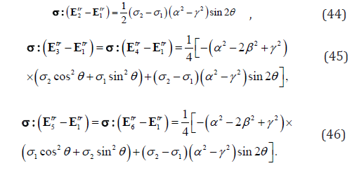
Thus

Substituting Eq. (26) into Eqs. (47)-(49) and assume θ1 = π/8 and c = 5.35 MPa , the relation between the thermodynamic driving force vs. σ (which decreases from 1.5 MPa to -1.5 MPa) can therefore be obtained. As shown in Figure 12, 12 Π is much larger than Π13 and Π15 . Thus, variant 1 is only able to transform into variant 2 first under this loading condition, just like that described in [44].
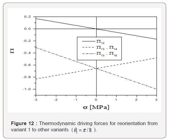
Similar results can be obtained for the case of θ2 = π/4, as showed in Figures 4 & 7.
The critical condition for reorientation from variant 2 to variant 1 is given by

while the critical condition of reorientation from variant 1 to variant 2 is

Because they are complimentary forward and reverse processes, Eqs. (50) & (51) may be written together as

Substitution of Eqs. (33) & (37) into Eq. (52) yields

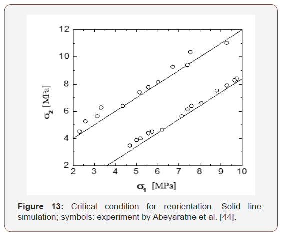
When θ = π/4, according to Figure 2(b) of Abeyaratne et al. [44], we have

Theoretically, orientation is the only difference between variant 1 and variant 2. Thus, ΠRe+ = −ΠRe− = ΠRe0. The observed non-symmetry in the forward and reverse reorientation between variant 2 and variant 1 might be due to the instrumental errors in testing or specimen preparation.

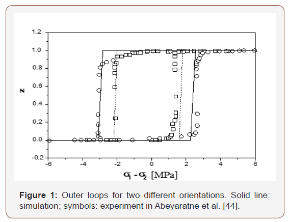
The result of Eq. (55) is plotted in Figure 13 against the experimental data (i.e., Figure 3 in Abeyaratne et al., 1996).
Suppose that the volume fraction of variant 1 is z , according to Eq. (77) in our previous paper [1], the evolution equation for reorientation can be written as

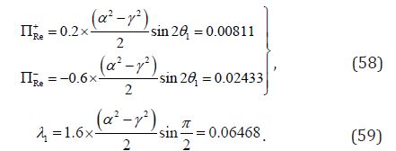
where λ1 can be determined from Figure 9 of Abeyaratne et al. [44]:

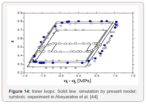
In the case of θ2 = π/8, similar result can be derived. Let 1 2 σ − σ vary between − 6.0 MPa and 6.0 MPa , the change of volume fraction of variant 1 vs. σ1 σ2 is shown in Figure 14. This is consistent with the experimental result in [44].
ΠRe+, ΠRe− and λ1 in Eqs. (54) & (57) can be determined from Figure 9 of Abeyaratne et al. [44], where the loading/unloading speed is 120s per cycle. If the cyclic speed is increased to 20s per cycle (as shown in Figure 8 of [44]), Re ΠRe+, and ΠRe− and λ1 can be calculated as
Using Eqs. (70) & (71) in our previous paper [1] and choosing the variation of σ1- σ2 accordingly, a group of internal loops can be obtained. Both analytical results and experimental data are plotted in Figure 14.
For both speeds with Eqs. (54), (57), (58) & (59), one has

This constant indicates that the sum of 1/2(ΠRe+- ΠRe−)+ λ1 does not depend upon the cyclic speed. It is noticed that the present model is only applicable for the quasi-static case since the parameters Re ΠRe+, ΠRe− and λ1 are expected to be material constants. For the non-quasi-static case, we have to consider the loading rate dependency for ΠRe+, and ΠRe− and λ1 as well. It should be emphasized that all numerical simulation results and related figures in this paper are copied from JZ’s research report [53] with permission.
Conclusion
The model proposed in our previous paper [1] is applied to simulate the thermomechanical behavior of a single crystalline CuZnAl in the forward/reverse phase transformation and reorientation between martensite variants in a single crystalline CuAlNi. We assume that the interior hysteresis loop is controlled by the jump of the critical driving force when opposite transition happens. Our simulation for these two single crystal materials is compared with the experimental data. Good agreement is achieved.
It is found numerically that the variation of load device energy in the phase transformation is at the same level as the variation of stored energy in the austenite-martensite inter-phase. On the other hand, the energy stored in the interface among martensite variants is significantly smaller. The simulation also suggests that loading rate effect cannot be ignored in martensite reorientation at a high rate.
Acknowledgement
None.
Conflict of Interest
The author has no conflict of interest.
References
- Zhu JJ, Liang NG, Cai M, Liew KM, Huang WM (2008) Theory of phase transformation and reorientation in single crystalline shape memory alloys. Smart Materials and Structures 17(1).
- Funakubo H (1987) Shape memory alloys. (Gorden and Breach Science Publishers).
- Birman V (1997) Review of Mechanics of Shape Memory Alloy Structures. Applied mechanics reviews 50(11): 629-645.
- Cisse C, Zaki W, Ben Zineb T (2016) A review of constitutive models and modeling techniques for shape memory alloys. International Journal of Plasticity 76: 244-284.
- Cisse C, Zaki W, Ben Zineb (2016) A review of modeling techniques for advanced effects in shape memory alloy behavior. Smart Materials and Structures 25(10).
- Yu C, Kang G, Kan Q (2018) A micromechanical constitutive model for grain size dependent thermo-mechanically coupled inelastic deformation of super-elastic NiTi shape memory alloy. International Journal of Plasticity 105: 99-127.
- Yu C, Kang G, Kan Q (2018) An equivalent local constitutive model for grain size dependent deformation of NiTi polycrystalline shape memory alloys. International Journal of Mechanical Sciences 138(139): 34-41.
- Xiao Y, Zeng P, Lei L (2018) Micromechanical modeling on thermomechanical coupling of cyclically deformed superelastic NiTi shape memory alloy. International Journal of Plasticity 107: 164-188.
- Movchan AA., Mishustin IV, Kazarina SA (2018) Microstructural Model for the Deformation of Shape Memory Alloys. Russian Metallurgy 4: 316- 321.
- Hartl DJ, Kiefer B, Schulte R, Menzel A (2018) Computationally-efficient modeling of inelastic single crystal responses via anisotropic yield surfaces: Applications to shape memory alloys. International Journal of Solids and Structures 136(137): 38-59.
- Yu C, Kang GZ, Kan QH, Xu X (2017) Physical mechanism based crystal plasticity model of NiTi shape memory alloys addressing the thermomechanical cyclic degeneration of shape memory effect. Mechanics of Materials 112: 1-17.
- Xiao Y, Zeng P, Lei LP, Zhang YZ (2017) In situ observation on temperature dependence of martensitic transformation and plastic deformation in superelastic NiTi shape memory alloy. Materials & Design 134: 111-120.
- Xiao Y, Zeng, P, Lei L (2017) Numerical study on mechanical response of superelastic NiTi shape memory alloy under various loading conditions. Materials Research Express 4(12).
- Wang J, Moumni Z, Zhang WH, Zaki WA (2017) thermomechanically coupled finite deformation constitutive model for shape memory alloys based on Hencky strain. International Journal of Engineering Science 117: 51-77.
- Wang J, Moumni Z, Zhang WH, Xu YJ, Zaki WA (2017) 3D finite-strainbased constitutive model for shape memory alloys accounting for thermomechanical coupling and martensite reorientation. Smart Materials and Structures 26(6).
- Wang J, Moumni Z, Zhang WH, Zaki WA (2017) thermomechanically coupled finite deformation constitutive model for shape memory alloys based on Hencky strain. International Journal of Engineering Science 117: 51-77.
- Sakhaei AH, Thamburaja P (2017) A finite-deformation-based constitutive model for high-temperature shape-memory alloys. Mechanics of Materials 109(21): 114-134.
- Long X, Peng X, Fu T, Tang S, Hu N (2017) A micro-macro description for pseudoelasticity of NiTi SMAs subjected to nonproportional deformations. International Journal of Plasticity 90: 44-65.
- Liu HW, Wang J, Dai HH (2017) Analytical study on stress-induced phase transitions in geometrically graded shape memory alloy layers. Part I: Asymptotic equation and analytical solutions. Mechanics of Materials 112: 40-55.
- Gu X, Zhang WH, Zaki W, Moumni Z (2017) An extended thermomechanically coupled 3D rate-dependent model for pseudoelastic SMAs under cyclic loading. Smart Materials and Structures 26(9).
- Chowdhury P, Sehitoglu H (2017) Deformation physics of shape memory alloys - Fundamentals at atomistic frontier. Progress in Materials Science 88(40): 49-88.
- Weafer FM, Guo Y, Bruzzi MS (2016) The effect of crystallographic texture on stress-induced martensitic transformation in NiTi: A computational analysis. J Mech Behav Biomed Mater 53: 210-217.
- Chowdhury P, Patriarca L, Ren GW, Sehitoglu H (2016) Molecular dynamics modeling of NiTi superelasticity in presence of nanoprecipitates. International Journal of Plasticity 81: 152-167.
- Chatziathanasiou D, Chemisky Y, Chatzigeorgiou G, Meraghni F (2016) Modeling of coupled phase transformation and reorientation in shape memory alloys under non-proportional thermomechanical loading. International Journal of Plasticity 82: 192-224.
- Bernardini D, Pence TJ (2016) A structured continuum modelling framework for martensitic transformation and reorientation in shape memory materials. Philosophical Transactions of the Royal Society a-Mathematical Physical and Engineering Sciences 374.
- Yu C, Kang GZ, Song D, Kan QH (2015) Effect of martensite reorientation and reorientation-induced plasticity on multiaxial transformation ratchetting of super-elastic NiTi shape memory alloy: New consideration in constitutive model. International Journal of Plasticity 67: 69-101.
- Yu C, Kang GZ, Song D, Kan QH (2015) A micromechanical constitutive model for anisotropic cyclic deformation of super-elastic NiTi shape memory alloy single crystals. Journal of the Mechanics and Physics of Solids 82: 97-136.
- Gu XJ, Zaki W, Morin C, Moumni Z, Zhang WH (2015) Time integration and assessment of a model for shape memory alloys considering multiaxial nonproportional loading cases. International Journal of Solids and Structures 54: 82-99.
- Zhu YG, Zhang Y, Zhao D (2014) Softening micromechanical constitutive model of stress induced martensite transformation for NiTi single crystal shape memory alloy. Science China-Physics Mechanics & Astronomy 57(10): 1946-1958.
- Yu C, Kang G, Kan Q (2014) Crystal plasticity based constitutive model of NiTi shape memory alloy considering different mechanisms of inelastic deformation. International Journal of Plasticity 54: 132-162.
- Panoskaltsis VP, Soldatos D, Triantafyllou SP (2014) On phase transformations in shape memory alloy materials and large deformation generalized plasticity. Continuum Mechanics and Thermodynamics 26(6): 811-831.
- Mehrabi R, Kadkhodaei M, Elahinia M (2014) A thermodynamicallyconsistent microplane model for shape memory alloys. International Journal of Solids and Structures 51(14): 2666-2675.
- Mehrabi R, Andani MT, Elahinia M, Kadkhodaei M (2014) Anisotropic behavior of superelastic NiTi shape memory alloys; an experimental investigation and constitutive modeling. Mechanics of Materials 77: 110-124.
- Junker P, Hackl K (2014) A thermo-mechanically coupled field model for shape memory alloys. Continuum Mechanics and Thermodynamics 26(6): 859-877.
- Junker P (2014) A novel approach to representative orientation distribution functions for modeling and simulation of polycrystalline shape memory alloys. International Journal for Numerical Methods in Engineering 98(11): 799-818.
- Auricchio F, Bonetti E, Scalet G, Ubertini F (2014) Theoretical and numerical modeling of shape memory alloys accounting for multiple phase transformations and martensite reorientation. International Journal of Plasticity 59: 30-54.
- Zhu YG, Zhang Y, Zhao D (2013) MICROMECHANICAL CONSTITUTIVE MODEL FOR PHASE TRANSFORMATION OF NiTi POLYCRYSTAL SMA. Acta Metallurgica Sinica 49: 123-128.
- Yu C, Kang GZ, Kan QH, Song D (2013) A micromechanical constitutive model based on crystal plasticity for thermo-mechanical cyclic deformation of NiTi shape memory alloys. International Journal of Plasticity 44: 161-191.
- Zaki W (2012) Time integration of a model for martensite detwinning and reorientation under nonproportional loading using Lagrange multipliers. International Journal of Solids and Structures 49(21): 2951- 2961.
- Zaki W (2012) An efficient implementation for a model of martensite reorientation in martensitic shape memory alloys under multiaxial nonproportional loading. International Journal of Plasticity 37: 72-94.
- Yu C, Kang GZ, Song D, Kan QH (2012) Micromechanical constitutive model considering plasticity for super-elastic NiTi shape memory alloy. Computational Materials Science 56: 1-5.
- Fu S, Huo Y, Muller I (1993) Thermodynamics of Pseudoelasticity - an Analytical Approach. Acta Mechanica 99(1-4): 1-19.
- Huo Y, Muller I (1993) Nonequilibrium Thermodynamics of Pseudoelasticity. Continuum Mechanics and Thermodynamics 5(3): 163-204.
- Abeyaratne R, Chu C, James RD (1996) Kinetics of materials with wiggly energies: Theory and application to the evolution of twinning microstructures in a Cu-Al-Ni shape memory alloy. Philosophical Magazine a-Physics of Condensed Matter Structure Defects and Mechanical Properties 73(2): 457-497.
- Muller I (1989) On the size of the hysteresis in pseudoelasticity Continuum Mechanics and Thermodynamics 1(2): 125-142.
- Abeyaratne R, Knowles JK (1993) A Continuum Model of a Thermoelastic Solid Capable of Undergoing Phase Transitions. Journal of the Mechanics and Physics of Solids 41(3): 541-571.
- Seelecke S (1996) Equilibrium thermodynamics of pseudoelasticity and quasiplasticity. Continuum Mechanics and Thermodynamics 8(5): 309- 322.
- Shield TW (1995) Orientation Dependence of the Pseudoelastic Behavior of Single-Crystals of Cu-Al-Ni in Tension. Journal of the Mechanics and Physics of Solids 43(6): 869-895.
- Liew KM, Zhu JJ (2004) Describing the morphology of 2H martensite using group theory part II: Case study. Mechanics of Advanced Materials and Structures 11(3): 227-248.
- Zhu JJ, Liew KM (2004) Describing the morphology of 2H martensite using group theory part I: Theory. Mechanics of Advanced Materials and Structures 11(3): 197-225.
- Otsuka K, Shimizu K (1974) Morphology and Crystallography of Thermoelastic Cu-Al-Ni Martensite Analyzed by Phenomenological Theory. Transactions of the Japan Institute of Metals 15(2): 103-108.
- Rogers RC (1996) Some remarks on nonlocal interactions and hysteresis in phase transitions. Continuum Mechanics and Thermodynamics 8(1): 65-73.
- Zhu JJ (1998) Constitutive theory of Martensite Phase Transformation in Shape Memory Alloys. Postdoctoral Research Report (Beijing: Institute of Mechanics, Chinese Academy of Sciences).
-
JJ Zhu, WM Huang, KM Liew. Initial Yield Surface of Shape Memory Alloy in Stress Induced Martensitic Phase Transformation. Glob J Eng Sci. 1(1): 2018. GJES.MS.ID.000504.
-
Phase transformation, Shape memory alloys, Thermomechanical processes, Microstructure, Constitutive behavior, Internal loop, Thermodynamic, Reorientation, Plane variant, Internal yield, Nucleation, Abeyaratne, Driving forces, Non-local interaction, Transition layer energy, Martensite lattice correspondence variants, Bain strain directions, Thermodynamic driving force, Strain curves, Cyclic temperature
-

This work is licensed under a Creative Commons Attribution-NonCommercial 4.0 International License.


