


 Research Article
Measuring of Speed Flow by Using Ultrasonic Transit- Time Sensor
Received Date: September 24, 2019; Published Date: September 26, 2019
Abstract
Measuring of the velocity of a flow with ultrasonic speedometer has no side effect on the pressure of the flow because it has no contact to it. In this paper, an ultrasonic speedometer is designed and manufactured based on measuring transit-time of the flow. The transmitter sends 40 KHz ultrasonic waves, these waves is received by the receiver sensor and the sending time is calculated by hardware and based on that the flow speed was calculated.
Keywords: Speed measurement, Ultrasound sensor, Ultrasonic waves, Piezoelectric, Proteus software
Introduction
In 1955, the first ultrasonic non-contact flowmeter was mounted in a laboratory that measured the flow of a plastic pipe. The first applications of these flowmeters were limited to measuring the flow of water in large diameter pipes. Primary non-contact flowmeters used the Doppler effect as the main factor of measuring the velocity, but the accuracy of them were depended on the part of the flow that benefits the Doppler shift [1]. Using Doppler spectral valve method was addressed this problem and was also used to improve the accuracy of the transit-time flowmeters. Dual-sensor flowmeters (Reflection, Transmission) was introduced in the mid-1990s. Fuji Electric (2005) introduced a dual-sensor Doppler flowmeter (pulse / transit-time) [2].
In order to achieve significant accuracy in measuring the production and delivery of products such as oil, gas and so on, choosing an appropriate flowmeter based on the characteristics of the flow is vital. For many years, ultrasonic flowmeters have been receiving endorsements from reputable worldwide organizations for use in financial-based transfers (Custody Transfer). For achieving the most accuracy in measuring the flow speed, choosing an appropriate flowmeter that is well designed is very important. Currently, using of ultrasonic flowmeters is exponentially increased and they accepted as a highly accurate flowmeter among the researchers, it seems that in the soon future ultrasonic flowmeters will consider as a reliable replacement of traditional ones. However, it has to be considered that choosing, designing and installing of ultrasonic flowmeter are very important steps that have to addressee to achieve the desire accuracy.
Ultrasonic flowmeters divided into three general categories that use ultrasonic waves in all three categories: transit-time, inhibitory and Doppler type. In this paper, we focused on the ultrasonic type that used for single-phase flows and has high accuracy. Also, it is usable for transmission bases and important financial matters. The second type of flowmeters, called inhibitory, works with the same as transit-time mechanism, but for measuring the flow it will attach to the external wall of the line and therefore it is less accurate comparing to the first type.
The Doppler type of flowmeters, which is less accurate than the previous two, used for flows containing impurities and solid particles. In this type of flowmeter, the presence of solid particles in the flow is required for measurement.
Theory and Principles of Ultrasonic Speedometer Design
In this type, transducers are both transmitter and receiver of ultrasonic waves; As shown in Figure 1, transducer A transmits a short pulse with a specific angle α to the pipe axis for transducer B. let tAB be time of this transmission and reception. Similarly, tBA be the transit time for transmission from transducer B to transducer A. Therefore, the difference between the time of transmitting and receiving is equal to Δt.

For a uniform flow with a constant sound speed (flow without temperature gradient), the flow speed is given by [3]:
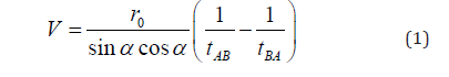
Where r0 is the radius of the pipe. For turbulent flow, speed profile is dependent on Reynolds number, namely [4]:
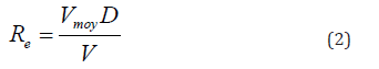
Where vmoy is the average speed of flow, D is the diameter of the pipe and v is the viscosity. For turbulent flow developed inside the pipe, the two-dimensional speed profile equals [5]:
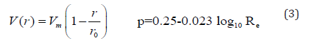
Where vm is the speed at the center of the tube, r is the distance from the center of the tube and p is a dependent variable on Reynolds number. The speed v in equation (1) is the average speed assuming the direct path of propagation. Integrating the speed profile in equation (3) on the line AB gives the value of v.
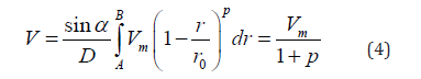
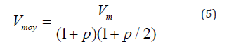
By integrating the speed profile in the pipe section, the average speed of the flow, vmoy is obtained:
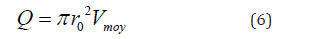
Consequently, the value of flow is:
How The Circuit Works
Circuit computing
The basis of this type of flowmeter is two transducers, that simultaneously emit an ultrasonic wave, are placed on either side of the line (Figure 2). One of the transducers is located upstream and the other downstream of the flow. Because the linear speed of the emitted wave from the upstream transducer is in the direction of the flow speed, it hits the downstream transducer earlier [6]. Wave transmission time from point 1 to point 2 and vice versa is calculated as follows:
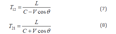

In the above equations, T12 is the wave transmission time from point 1 to point 2, T21 is the wave transmission time from point 2 to point 1, C is the sound speed, V is the speed flow and θ is the angle between the pipe axis and the demarcation line of two transducers. By removing C from the above two equations we will have:
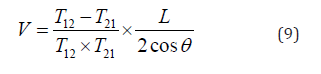
In the circuit designed in this paper, we used the transit-time principle, the difference is that it uses a receiver and a transmitter sensor to reduce the price. Therefore, only one of equations (7) and (8) is used to calculate the speed [7]. The flow speed is dependent on C obviously (the sound speed in a specified flow), so it has to be considered that due to the influence of temperature on C in different flows and its influence on reducing the accuracy of the speedometer, C is removed from the equation (9) to become independent from the flow speed to increase measurement accuracy.
Steps of operation of the ultrasonic flowmeter
• Wave transmission: In the first step, the signal processing unit (SPU) transmits an electrical signal to the piezoelectric transducer (piezoelectric crystal, Figure 3) and this will transmit the sonic pulse into the stream by the crystal.
• Receiving wave: The sonic pulse passes through the flow and reaches the opposite transducer, creates a vibration in the crystal that generates and outs an electrical signal.
• Signal conversion: The final electrical signal enters the SPU unit and is processed.
• Signal Processing: Depending on the manufacturer, an algorithm is defined in SPU that can obtain T12 and T21 by signal processing and calculate the average flow rate.
• Output renewal: This operation is performed again by the SPU to obtain measurement and accurate deduction of the average speed of flow (Figure 4).


Circuit Design
First by microcontroller programming, a 40 kHz square wave is generated, and the square wave voltage level is amplified by a two-stage common emitter circuit and transmit to the ultrasonic transmitter (Figure 5).

It should be noted that in the transmitter circuit using a coupling capacitor, the possible DC value is eliminated, and the signal is transmitted to the transmitter sensor for wave propagation in the flow [8].
When the wave propagates in the flow, the timer number 1 of microcontroller start counting. When the wave reaches the receiver, its voltage range is a few millivolts, so the received wave must be amplified, the received wave can be amplified by the opamp or transistor amplifiers, in this article, received wave is amplified by the opamp amplifiers. It then enters the envelope detector and the signal envelope is extracted.

The envelope detector actually amplifies a high-frequency signal at its input and displays signal envelope as a low-frequency signal at the output. Envelope of a signal is a spatial which the wave is enclosed.
The extracted signal from the envelope is given to a voltage comparator because the final output voltage must be square in order to be detectable by the microcontroller. Therefore, the task of voltage comparator is to convert a sine waveform to a square waveform.
By this method, the received wave by the receiver is converted to zero and one (known data for microprocessor), the comparator output is connected to interrupt 0 microprocessor by a diode, whereby the microcontroller interrupt is activated and the value of timer 1 is calculated. (So, by using the equation 9 we can calculate the speed and the result is displayed by the LCD connected to the microcontroller.

An LED can be used to be notified from the receiving wave that we insert it in the following circuit (Figure 7) after the comparator.When the wave received in receiver, the comparator output goes to positive saturation and the LED illuminates.
Figure 8 shows the schematic of the ultrasonic speedometer simulated by proteus and programed by code vision software, and the Figure 9 shows the circuit made of this speedometer.


Implementation
The steps that must be considered in implementing this speedometer are as follow:
• During mounting the flowmeter, we have to be careful about the frequency of its vibrations to avoid the frequency range of SPU and the transducers. For this purpose, the manufacturer must provide natural frequency and installation condition. In addition, temperature control is an important factor for minimizing the effect of ambient temperature.
• During the installation of the flowmeter we have to avoid putting it in the curve section of the pipe. In addition, the level of radiation of the transducer at the point of contact should be similar impedance to the pipe impedance (for impedance matching).
• One of the problems with ultrasonic flowmeters is the signal interference. Some control valves also make noise. Therefore, in this case, the line arrangement should be changed, or the valve should be moved far from the flowmeter to avoid interface. When the ultrasonic signal interfaced with noises, it will be very difficult to detect pulse from noise by the transducer. (The negative effect of this issue, especially when the noise is of an ultrasonic signal type). One possible solution to reduce this effect is to increase the energy of the transducer. However, for safety reasons, the energy of the power supply cannot be increased beyond a certain limit. Moreover, installing flowmeter near the control valve can adversely influence the flowmeter performance because by opening and closing the control valves, a turbulent flow is created and reduces the accuracy of measurement.
• In the circuit mentioned above, considering the cost, two sensors are used, one of them only transmits the wave and the other receives the wave. As a result, only one time is calculated and at the end, the calculated speed depends on C (sound speed in fluid). We have to consider that, C is affected by temperature, in this paper, we neglect this effect of temperature on C. To improve the accuracy, a variable NTC resistor (Figure 10) can be used which acts as a temperature sensor and calculates the temperature or can eliminate the dependency of flow speed to sound speed in the flow by using of two receiver and transmitter sensors.
• (Figure 10).

• L, which represents the distance between the transmitter and receiver in the flow speed calculation equation and depends on the pipe diameter is considered as a constant value in microcontroller programming, which limits the device to a specified diameter pipe. To solve this problem in microcontroller programming, the radius can be input as an input variable and the L is calculated in the corresponding formula.
• The sensor angle is 45 degrees, which is empirically obtained.
• An ultrasonic module can be used to increase the accuracy and ease of circuit design. This module includes a pair of ultrasonic transmitter and receiver sensors as well as noise catcher ICs and opamp amplifiers to amplify the transmitted and received signals. This module can be connected directly to the micro without any interface.
Conclusion
The distinguishing feature of these types of speedometers is that they can be used to measure the speed of a flow accurately because ultrasonic speedometers measure the flow speed without having contact with the flow, which causes no pressure drop. In general, the advantages of ultrasonic measurement systems include lightness and low volume, sensor diversity, high accuracy in measurement, easy operate, low maintenance cost and lowpressure drop-in measurement.
Acknowledgement
None.
Conflict of Interest
No conflict of interest.
References
- Y Hojjat, AR Ghane, Sh Mirzamohamadi (2013) Design and fabrication of a transit time ultrasonic flow meter. Moddaress Mechanical Engineering Journal 13(5): 153-156.
- A Farahani (2013) Measuring fluid flow by using ultrasonic waives. Oil and gas exploration & production 98: 41-45.
- Lynnworth LC, Liu Y (2006) Ultrasonic Flowmeters: Half-Century Progress Report, 1995-2005. Ultrasonics 44: 1371-1378.
- PANAMETRICS-NDT (2006) Ultrasonic Transducers Technical Notes. OLYMPUS, pp. 40.
- Jacobson S, Lynnworth ALC, Korba JM (1988) Differential Correlation Analyzer. US Patent.
- Yamamoto T (2005) The Best of Both World-Hybrid Ultrasonic Meter Combine UVP &Transit-Time Technology. Flow Control XI: 34-40.
- Bell Stephanie (2001) A Beginner’s Guide to Uncertainty of Measurement, Centre for Basic, Thermal and Length Metrology, National Physical Laboratory.
- Ultrasonic sensors (2012).
-

This work is licensed under a Creative Commons Attribution-NonCommercial 4.0 International License.


