


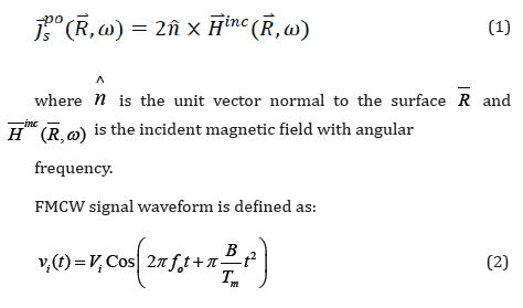
 Mini Review
Frequency-Domain Characteristics in FMCW Radar
Received Date: October 29, 2021; Published Date: November 09, 2021
Abstract
This paper presents and evaluates a frequency domain characteristic in FMCW radar (Frequency Modulated Continuous Wave Radar). FMCW radar is a form of radar where the frequency of the transmitted signal is continuously varied at a known rate over a defined time period. In this paper, FMCW radar determines a target range by measuring the beat frequency between a transmitted signal and the received signal from the target and Combines between PO and radar single. The approach based on frequency domain physical optics for the scattering estimation and FMCW Radar signal processing. The results represented graphically and illustrated by figures.
Keywords:Radio wave; FMCW radar; Cloud profiling radar
Introduction
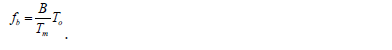
Frequency Modulated Continuous Wave (FMCW) radar is a form of radar where the frequency of the transmitted signal is continuously varied at a known rate over a defined time period. The reflected frequency signal is received by the radar and compared. The transceiver generates a signal of linearly increasing frequency for the frequency-sweep period. The signal propagates from the antenna to a static target and back. The value of the received-signal frequency compared to the transmitted-signal frequency is proportional to the propagation range. In addition, advantage of FMCW radar is its ability to adjust the range of frequencies of operation to suit the material and targets under investigation if the antenna has an adequate Pass-band of frequencies. This radar system mixes the wave reflected by a target object and part of the radiated wave to obtain a beat signal that contains distance and speed components. For large scattered, the physical-optics approximation is an efficient method in the frequency domain [1,2]. This physical optics (PO) approximation is initially applied in the frequency-domain with the inverse Fourier transform [3-6]. With FMCW, the high-frequency circuitry for beat signal detection is relatively simple and distance can be directly obtained. By mixing the received FMCW and transmitted FMCW signals, the system obtains a beat signal having a frequency fb. [7] studied the Radar wave propagation characteristics in FMCW by using the frequency domain physical optics. In this paper, we use the frequency-domain physical optics with the inverse Fourier transform [3] and [6]. In addition, we will focus on some numerical results for the frequency-domain.
Formulation
For a perfectly conducting body, the frequency-domain PO-induced current distribution over the illuminated surface is [8-10]:
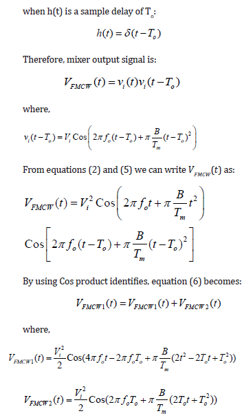
The equation (7) describes a linearly increasing FM signal (chirp) at about twice the carrier frequency with a phase shift that is proportional to the delay time To, this term is generally filtered out. Equation (8) describes a beat signal at a fixed frequency
Frequency – Domain OP
The frequency transfer function H(ω) is defined as
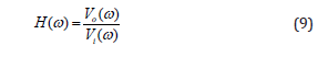
where 𝑉𝑖(𝜔) is the input waveform in frequency domain physical optics, this is just a magnitude of the source.
The output Voltage 𝑉𝑜(𝜔) is calculated from 𝐸𝑝𝑜(𝑅, 𝜔) by considering the receiver antennas as [11-12],

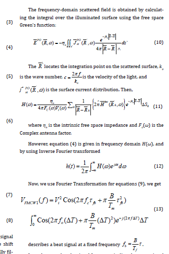
It can be seen that the signal frequency is directly proportional to the time delay time τ , and hence is directly proportional to the round-trip time to the target.
Numerical Results
Figures (1-4) represent the relation between the frequency transfer function 𝐻(𝜔) and the angular frequency ω and show the values of the frequency transfer function 𝐻(𝜔) at λ = 1, 2, 3, and 5 respectively. Figures (1-4) show that increasing in the values of the frequency domain transfer function 𝐻(𝜔) due to the increasing in the wavelength λ and the increases in the wavelength λ due to the decay in the frequency. Our series expansion gave good approximations of the field values. The peak in the Figures (3) and (4) at λ = 3 and 5 are small peak compared to the peak in Figures (1) and (2) at λ = ½ and 1. The results represented graphically and illustrated by figures.


Conclusion
We obtained the frequency domain linear system analysis for FMCW which obtained by calculating the integral over the illuminated surface using the free space Green’s function and we use the frequency-domain physical optics with the inverse Fourier transform. We conclude from the present analysis that the increasing in the wavelength λ due to the decay in the frequency, gave the increasing in the values of the frequency transfer function 𝐻(𝜔).
Acknowledgement
None
Conflict of Interest
No conflict of interest.
References
- WVT Rusch, PD Potter (1970) Analysis of Reflector Antenna, New York: Academic, pp. 46-49.
- RF Harrington (1961) Time-Harmonic Electromagnetic Fields, New York: McGraw- Hill, pp. 127.
- EM Kennaugh, RL Cosgriff (1958) The use of impulse response in electromagnetic scattering problems, IRE Natl Conv Rec 1: 72-77.
- S Hatamzadeh-Varmazyar, M Naser-Moghadasi (2008) An Integral Equation Modeling of Electromagnetic Scattering from the Surfaces of Arbitrary Resistance Distribution Progress In Electromagnetics Research B 3: 157-172.
- CA Valagiannopoulos (2008) Electromagnetic Scattering from Two Eccentric Metamaterial Cylinders with Frequency-Dependent Permittivities Differing Slightly Each Other Proress In Electromagnetics Research B 3: 23-34.
- EM Kennaugh, DL Moffatt (1965) Transient and impulse response approximation, Proc IEEE, pp. 893-901.
- Ghada M Sami (2009) Radio Wave Propagation Characteristics in FMCW Radar. J Electromagnetic Analysis & Applications 1: 275-278.
- E Yuan, WVT Rusch (1994) Time-Domain Physical Optics. IEEE Trans. On Antenna and Propagation 42(1).
- LX Yang, DB Ge, B Wei (2007) FDTD/TDPO Hybrid Approach for Analysis of the EM Scattering of Combinative Objects, Progress In Electromagnetics Research, PIER 76: 275-284.
- Ghada M Sami (2013) Time-Domain Analysis of a Rectangular Reflector. Journal of Modern Physics 4(10): 1437-1440.
- S Ishigami, H Iida, T Iwasaki (1996) Measurements of Complex Antenna Factor by the Near 3-Antenna Method, IEEE Transaction on Electromagnetic compatibility 38(3): 424-432.
- L Li, CH Liang (2004) Analysis of Resonance and Quality Factor of Antenna and Scattering Systems Using Complex Frequency Method Combined with Model-Based Parameter Estimation. Progress In Electromagnetics Research, PIER 46: 165-188.
-

This work is licensed under a Creative Commons Attribution-NonCommercial 4.0 International License.


