 Mini Review
Discussion of Solutions for Combining Rotations
Shuh Jing Ying*
Mechanical Engineering, University of South Florida, Florida, USA
Shuh Jing Ying, Mechanical Engineering, University of South Florida, Tampa, Florida, USA.
Received Date: June 23, 2020; Published Date: July 06, 2020
Abstract
Combining two rotations into one is described in detail in the book Advanced Dynamics by Shuh Jing Ying. The solutions are available and are verified as presented in the 2019 ASEE Annual Conference. The repeated use of the combination of two rotations into one allows the combination of many rotations into one. This is especially useful when time is of the essence, such as for a guided missile shooting enemy’s missile in the mid-air. So, this is a very important subject. However, when carefully looking into details, it is discovered that the solutions are not unique. Since this is a very important subject, it is worthwhile to be discussed.
Introduction
If this is the first time that you have seen how two rotations are combined into one rotation, it is not surprising since Ying’s Advanced Dynamics has a limited distribution. So, the ideas expounded below may seem innovative and new, yet they are not. The purpose of this paper is to demonstrate the use of rotation operators to solve this problem and to inspire readers to create other innovative solutions. This is the educational purpose of this paper. Since this solution is based on rotation operators, and rotation operators are often overlooked in dynamics, let us begin with a brief historical overview of rotation operator. Then, I will start from the definition of rotation operator, provide examples of operations, and then verify the solutions.
Rotation operator was first introduced by JW Gibbs in 1901 as mentioned in Ying’s Advanced Dynamics [1]. A search of the online scientific literature revealed no papers directly related to this study. However, there are some papers parallel to the rotation operator in this paper, for example, “Beyond Euler angles: Exploiting the angle- axis parametrization in a multipole expansion of the rotation operator” by Mark Siemens et al. [2] uses angle and rotating axis as the arguments for the operator, similar to the rotation operator in this paper but the application is in a totally different field, quantum mechanics. Other useful references related to the vector and tensors analyses include the following: Advanced Dynamics by D Greenwood [3]; Vector analysis and Cartesian Tensors by D Bourne [4] and From Vectors to Tensors by JR Ruiz-Tolosa [5].
Review of Rotation Operators
Definition of rotation operator
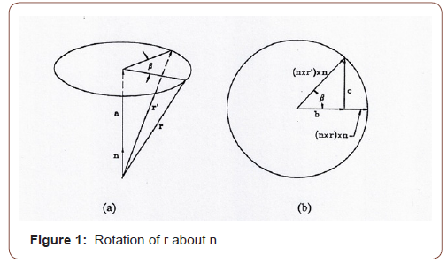
The notations used in the equations are as follows: bold letters represent vectors, a double arrow on the top of a letter indicates a dyad or dyadic. A pair of vectors written in a definite order, such as ij, is called dyad and a linear combination of dyads is known as a dyadic. Now, consider that a position vector r is rotated with respect to vector n by angle β to r’. The angle β is measured in the plane perpendicular to n, containing the ends of vectors r and r’ in that plane as shown in Figure 1. Let a be a vector with the direction of n and the magnitude of the component of r along n, so that
a = n(r.n)
Let b and c be vectors in the circular plane, which is the top view of Fig. 1a looking down directly along – n. Hence
r' = a + b + c
The radius of the circle is r sinθ where θ is the angle between r and n, or

So, the rotation operator is a dyadic and is defined as a function of rotating axis n and angle β.
Properties of the Operator
As β=0,


Combination of Two Successive Rotations about Different Axes by One Rotation
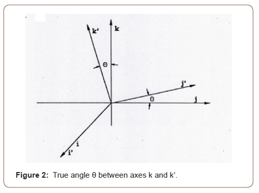
Suppose a rigid body to be rotated by two steps. First it is rotated about the k axis by an angle of φ and then it is rotated about k’ axis by an angle of ψ. The directions of k and k’ are known, and the plane containing them is determined. Choose the x axis perpendicular to the plane. Suppose the true angle between k and k’ is θ, as shown in Figure 2, then


And the two consecutive rotations may be expressed by

According to Euler’s theorem that the most general displacement of a rigid body with one point fixed is equivalent to a single rotation about some axis through the point, these two rotations can be combined into one, i.e.,

Through some tedious manipulations and with the use of the following identities


From Eq. (23) the solutions of n and β can be determined. However, when look carefully there are three possible solutions. The first set of solutions is

In Eq (29) because of the missing of sin(β⁄2) or cos(β⁄2), the vector n is not a unit vector, but the vector is in the same direction as in the other two possible solutions. But β = sin(-1)(A). The rotated angle is not the same as in the first solution. It cannot be the right solution. To make it clear a numerical example is given below.
Numerical Example
Let us consider the coordinates as follows: taking the X axis parallel to latitude with the positive X pointing east, Y axis parallel to longitude with positive Y pointing north and Z axis perpendicular to the surface of Earth, the origin of the coordinates at the center of the ball joint. The center line of the missile is along the position vector
r=10 i+20 j+50 k
• Suppose that it is required to rotate π/36 with respect to i axis and then rotate π/8 with respect to k axis. Find the final position vector of missile.
• To illustrate the use of the formulas for the combined rotation, calculate the rotation of the missile from the original position by angle of β about the axis n. And compare the results. (a) Calculate β and n according to first set of the solutions as given in Eqs (24) and (25); (b) according to second set of solutions as given in Eqs (26) and (27); (c) according to third set of the solutions as given in Eqs (28) and (29).
Solution:
1. Calculate the final position vector of the missile after two consecutive rotations.

This is the final position vector of the missile.
Calculations of β and n for the combining rotations into one and find the final position vector of the missile

n ∙ r = (0.2141998 i + 0.04260687 j + 0.9758599 k) ∙ (10 i + 20 j + 50 k)
=2.141998 + 0.8521374 + 48.792995 = 51.7871304
n × r = (0.2141998 i + 0.04260687 j+0.9758599 k) × (10 i +20 j + 50 k)
=4.283996 k - 10.70999 j - 0.4260687 k + 2.1303435 i + 9.758599 j - 19.517198 i
= -17.3865545 i - 0.951391 j + 3.8579273 k
r2= (1-0.920219059) (51.7871304) (0.2141998 i + 0.04260687 j+ 0.9758599 k) + 0.920219059 (10 i +20 j + 50 k) + 0.391403733 (-17.3865545 i-0.951391 j+3.8579273 k)
=0.884993461 i+0.176035651 j+4.03188813 k + 9.20219059 i+18.40438118 j+46.01095295 k
- 6.805162335 i-0.372377988 j+1.510007147 k
=3.282021716 i+18.20803884 j+51.55284823 k
=3.282 i+ 18.208 j+51.553 k (31)
Compare Eq. (31) with Eq. (30), we find that they are identical. So, they reached the same results.
b. According to the second set of solutions, Eqs. (26) (27)

n ∙ r = 0.8556254 + 0.340388 + 19.49046 = 20.6864734
n x r = k (0.08556254 x 20) – j (0.08556254 x 50) - k (0.0170194 x 10)
+ i (0.0170194 x 50) + j (0.3898092 x 10) – i (0.3898092 x 20)
= - 6.945214 i - 0.380035 j + 1.5410568 k

Eq. (33) is also different from Eq. (30) so this numerical example confirms that the third set of the solutions cannot be the right solution.
Conclusion
It is found that there are three possible solutions for the combining rotations mathematically. One is already confirmed to be the true solution however the other two solutions proved not to be the solution. In this report the first set of the solutions is the right one with the right β and n for the combining rotations. In the second set, the unit vector n for the axis of the combining rotations is the same as n in the first set but the value of β is much larger so the result of the combining rotations must be different from the true value. The numerical example confirms this situation. In the third set of solutions, although the vector n is in the same direction as n in the first set but the magnitude is different so it will not be a unit vector and the value of β is different from β in the first set, so it is expected that the result of the combining rotations will not match the first set. Numerical example just confirms this argument. There is no surprise in this study. This is just to report that the solution for the combining rotations is further studied.
Acknowledgement
None.
Conflict of Interest
No conflict of interest.
References
- Ying SJ (1997) Advanced Dynamics. Book, AIAA Education Series.
- Siemens M, Hancock J, Siminovitch D (2007) Beyond Euler Angles: Exploiting the Angle-Axis Parametrization in a Multipole Expansion of the Rotation Operator. in Solid State Nuclear Magnetic Resonance 31(1): 35-54.
- Greenwood D (2003) Advanced Dynamics. Book, Cambridge University Press.
- Bourne D (2018) Vector Analysis and Cartesian Tensors. Book, Boca Raton, FL Chapman and Hall/CRC.
- Ruiz Tolosa JR (2005) From Vectors to Tensors. Book, Springer.
-
Shuh Jing Ying. Discussion of Solutions for Combining Rotations. Glob J Eng Sci. 6(1): 2020. GJES.MS.ID.000628.
-
Dynamics, Rotation operator, Quantum mechanics, Vector, Angle
-

This work is licensed under a Creative Commons Attribution-NonCommercial 4.0 International License.


