 Research Article
Analysis of Mechanical Properties of Long-Span Reinforced Concrete Composite Slabs Under Different Splicing Methods
Liu Hai, School of Electrical Engineering, Chongqing university, China.
Received Date: February 21, 2022; Published Date: May 25, 2022
Abstract
Based on the long-span slab in an assembled building project, ABAQUS is used to simulate the mechanical properties and failure modes of the slab under the condition of the whole span cast-in-place slab and the two-way composite slab with different splicing methods. The finite element simulation results show that the integrate performance of the cast-in-place slab is better than the composite slabs, but the mechanical properties of the parallel splicing twoway composite slab are not different from the cast-in-place slab; The stress concentration and the first crack are easy to appear at the cast-in-place joint of the intermediate span composite slab. With the increase of the uniform load on the slabs, the cracks will develop from the later cast-in-place joint to the side span composite slabs, and the concrete at the bottom of the slabs will crack and fail; If truss reinforcement composite slabs are used for large-span slab, two-way composite slab shall be adopted. Cast-in-place joint shall be arranged in the direction with less stress but not be arranged bidirectionally.
Keywords:Large-span; Composite slab; Mechanical property; ABAQUS; Plastic damage
Introduction
Composite slab is a kind of prefabricated slab composed of precast bottom slab and cast-in-place reinforced concrete. The prefabricated bottom slab is not only a part of the slab, but also a permanent formwork for the cast-in-place reinforced concrete layer, which reduces the amount of cast-in-place and formwork erection, improves the efficiency and saves the construction period.
Based on many excellent properties of composite slab, scholars at home and abroad have carried out systematic research on it. Bayasi and izzuddin Ba concentrated on the calculation methods of shear strength, crack resistance and deflection of the composite surface of composite slab [1-2]; Sang Aihua and others applied the composite slab to the new building of Xi Yuan Hotel and it was considered that the composite slab has good integrity and continuity, reduces the branch modulus and cast-in-place quantity, and can save the clear height of the slab [3]. Guo Qijun and others discussed the normal section strength, shear strength, crack resistance and deflection of composite slab [4]; Xu Youlin and others conducted and load tests on the double-layer reinforced composite slab. The test results showed that the stiffness, strength and crack width of the composite slab can meet the requirements of the specification. At the same time, it is proposed that the joint of the composite slab should be arranged at the position with less stress as far as possible [5]; Ling Ru et al. Conducted experimental research on the impact of different splicing methods on the composite slab. The test results showed that the cracks at the joint of the composite slab appear later, and most of them were located on both sides of the joint, and the crack width was also small [6].
At present, there have been a lot of researches on the shear strength, short-term stiffness, crack resistance and deflection of the composite slab at home and abroad, but the research on the mechanical properties of the composite slab under different splicing methods is slightly insufficient, especially when the slab span is large, the joint mode directly affects the bearing capacity and seismic performance of the composite slab. Furthermore, document [7] stipulates that “prestressed concrete precast slab should be used for composite slab with span greater than 6m”, but it is not clear whether truss reinforcement can be used for composite slab when the slab span is greater than 6m. Based on the above two research gaps, combined with the particularity of the engineering projects currently contacted by our company, ABAQUS is used to simulate a long-span slab in the project, analyze the mechanical properties of the composite slab under different splicing methods, and compare it with the integral cast-in-place slab, so as to lay a foundation for subsequent design and construction.
Design of Truss Reinforced Composite Slab
The large-span slab is taken from an actual project. as shown in Figure 1, the span is 8000mm × 9000mm and the thickness is 220mm. The reinforcements are double layers two-way reinforcement whose specification is 10@150. If the composite slab is adopted, the thickness of the prefabricated bottom slab is 60mm and the thickness of the cast-in-place layer is 160mm.
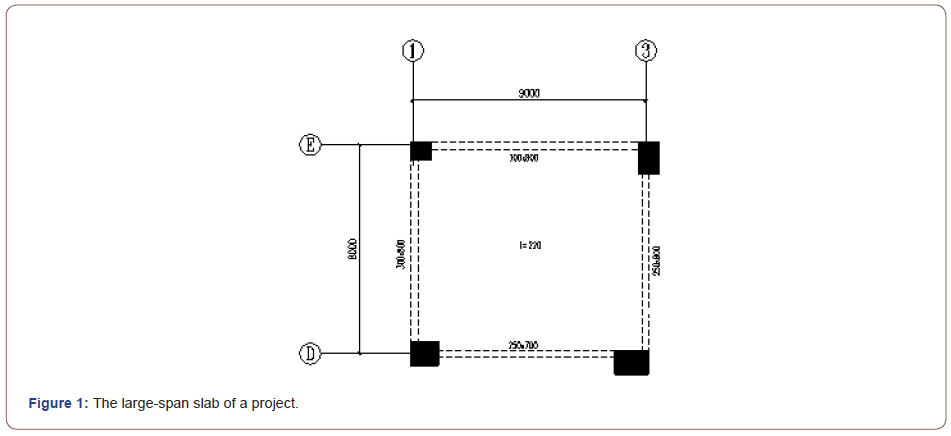
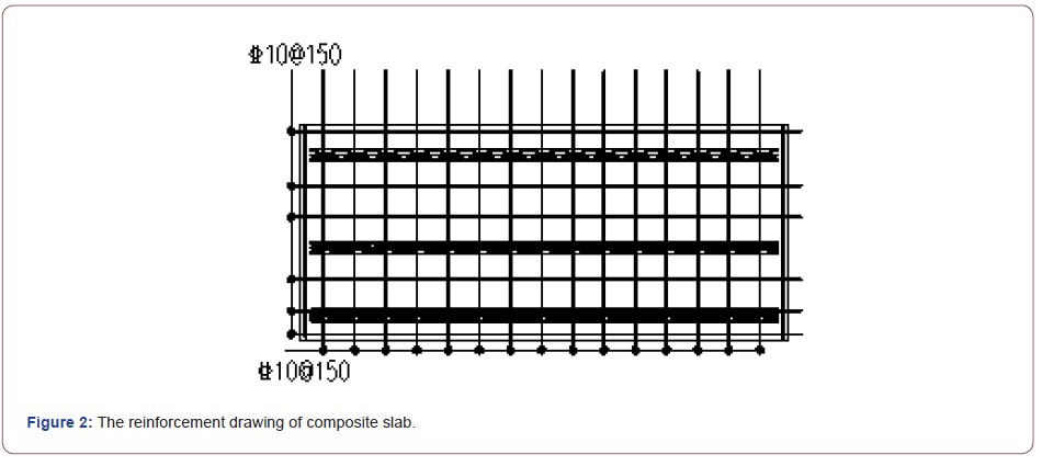
According to the relevant provisions of documents [7-8], the slab adopts two-way composite slab, the width of post cast strip between slabs is 300mm, and the anchorage length of stressed reinforcement at the bottom of precast slab extending into the cast-in-place strip is 290mm. The reinforcement of single two-way composite slab is shown in Figure 2.
Analysis Model of ABAQUS
At present, there are two types of reinforced concrete finite element models: separated model and integral model. The separated model is to model the reinforcement and concrete respectively, that is to say the concrete is simplified into solid elements, and the reinforcement is simplified into beam elements or truss elements. The bonding and sliding between reinforcement and concrete can be simulated by setting contact relationship or adding corresponding interface elements. The integral model disperses the reinforcement in the whole element according to the proportion of the reinforcement in the element. The calculation cost of the whole model is the lowest and the accuracy is low. In this paper, the strain distribution and plastic damage of reinforcement and concrete need to be simulated respectively, so the separated model with high accuracy is adopted.
Elements type
Concrete is an isotropic material, which can be considered as a uniform solid element. In ABAQUS, the eight-node hexahedral element C3D8R can be used for simulation. This element has two properties: tensile cracking and crushing; The reinforcement can be simulated by two node linear truss element T3D2, which can only bear the action of uniaxial tension and pressure.
Material constitutive parameters
The simulated reinforcement can be regarded as an ideal elastic-plastic material, and the plastic damage model is adopted for concrete. The model of slab reinforcement is HRB400 (grade III steel), the strength grade of concrete is C30, the measured yield strength of reinforcement is 472MPa, and the measured standard value of concrete axial compressive strength is 22.8MPa. According to “code for design of concrete structures GB50010-2010” [9], the constitutive parameters of reinforcement and concrete can be obtained, that is, the elastic modulus of concrete is taken as 2×10N/ mm2, and the Poisson’s ratio is taken as 0.2; The elastic modulus of reinforcement is taken as 2×10N/mm2, and the Poisson’s ratio is taken as 0.3.
The double linear constitutive model is selected for reinforcement and the plastic damage model is selected for concrete, and the development or crushing of concrete cracks can be judged by plastic damage parameters. In the process of ABAQUS simulation, the plastic damage parameters will reduce the stiffness matrix of concrete after damage, so as to achieve the purpose of simulating the damage evolution process of concrete and can accurately reproduce the failure process of tensile cracking or crushing of concrete materials. Therefore, the introduction of plastic damage parameter is of great significance to explore the mechanical failure characteristics of composite slabs.
Appendix C of “code for design of concrete structures Gb50010- 2010” gives the calculation method of tensile damage parameter dt and compression damage parameter dc, as shown in formula (1) ~ formula (5).

In the above formula, ft,r and fc,x respectively represent the representative value of concrete uniaxial tensile strength, the value of ft,r is 2.01mpa, and the measured value of fc,x is 22.8MPa; , ε t rand c , ε r respectively represent the peak tensile strain and compressive strain corresponding to the representative value of uniaxial tensile strength and uniaxial compressive strength, and the corresponding values are 9.52 × 10⁻⁵ and 1.52 × 10⁻³; t α and c αrespectively represent the parameter values of the descending section of the stress-strain curve of concrete under uniaxial tension and compression, which can be obtained according to the linear interpolation method, t α and c α then the values of and are taken as 1.26 and 0.92 respectively.
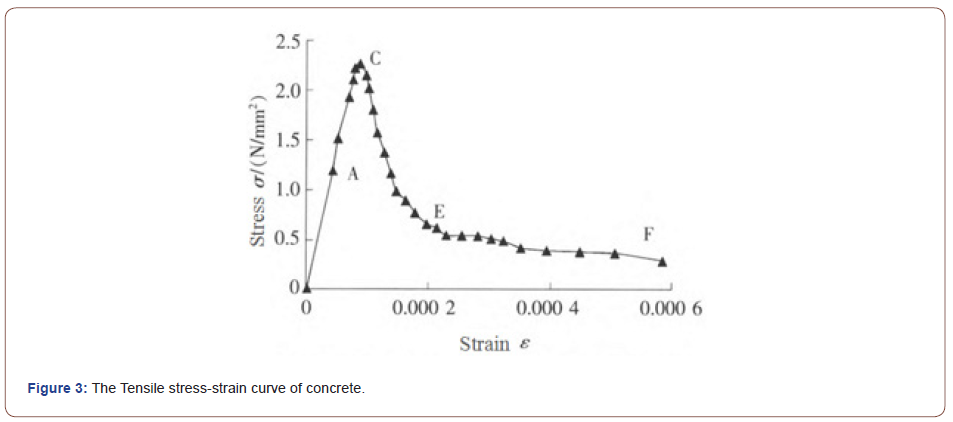
Guo [10] and others obtained the tensile stress-strain curve of concrete through the material property test, as shown in Figure 3. At the same time, they gave the location of each key point and the crack width of corresponding concrete when the concrete was damaged, as shown in Table 1.
Table 1: Quantitative description of concrete cracks under different stress stages.

Contact and boundary conditions
Because the expansion coefficients of reinforcement bar and concrete are similar, and the ribbed reinforcement bar can enhance the bonding performance with concrete, the simulation process considers that the relative slip between reinforcement bar and concrete can also be ignored, and the embedded region command can be used to restrict them together; At the same time, it is considered that the deformation of the prefabricated bottom plate of the composite slab is coordinated with that of the cast-in-place layer. According to a lot of experimental studies, the artificial roughening treatment on the surface of the prefabricated bottom plate and the existence of truss reinforcement bars make the composite slab will not undergo shear failure before bending failure. Therefore, it can be considered that there is no relative slip between the prefabricated bottom plate and the cast-in-place layer, In the process of simulation, the prefabricated base plate and castin- place layer can be bound together with the “tie” command.
Considering that in the actual project, the composite slab needs to be laid on the beam first (the bending stiffness and torsional stiffness of the beam are large), and then poured concrete to form a whole. It can be seen from the literature [11] that the error of the calculation method of the slab according to the fixed support of four sides is small, so the boundary condition of the composite slab is set as the fixed support of four sides, That is, 6 degrees of freedom (3 translational degrees of freedom + 3 rotational degrees of freedom) need to be constrained.
Load application
Apply a uniformly distributed load perpendicular to the slab, and the amplitude increases monotonically from 0 kN/m2 to 60 kN/ m2 until the slab is completely damaged.
Model building
Based on the above theoretical basis and modeling experience, the whole span cast-in-place slab model (hereinafter referred to as model A), parallel splicing two-way composite slab model (hereinafter referred to as model B) and parallel cross splicing twoway composite slab model (hereinafter referred to as model C) are established respectively, as shown in Figure 4.

Finite Element Analysis Results
Displacement analysis
According to table 3.4.3 of “code for design of concrete structures Gb50010-2010”,when the slab span meets 7m ≤ l0 ≤ 9m ,the allowable deflection limit is 0 l / 250 , that is, when the slab span is 8m, the allowable deflection limit is 8000mm/ 250 =32mm, and the slab uniformly distributed load corresponding to the allowable deflection limit is the ultimate load.
Selecting the point with the largest deflection in the slab span and extracting the load displacement curve, as shown in Figure 5. The damage of concrete at the bottom of slab under ultimate load is shown in Figure 6.
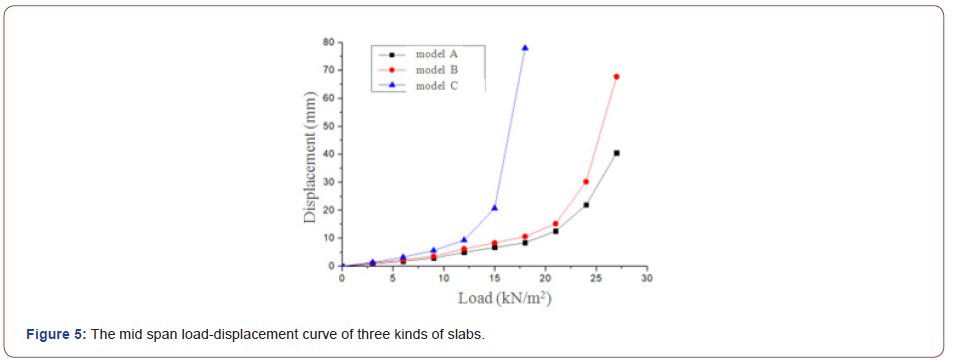
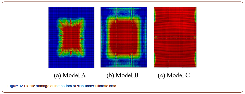
It can be seen from Figure 5 that with the increase of the uniformly distributed load on the slab, the mid span displacement increases. When approaching the allowable deflection limit, if the load continues to increase, the displacement will have a sudden change. In general, under the same slab load, the mid span displacement of model A is the smallest, the model B is the second, and the model C is the largest. The ultimate load that model A can bear is about 25kN/m2. At this time, the concrete at the bottom of the slab is almost cracked. Continue loading will cause the mid span displacement change suddenly, it is very easy to cause the brittle failure of the slab; The ultimate load that model B can bear is very close to that of model A at about 24kN/m2, and at this time, almost all the bottom of the mid span composite slab is cracked, and it develops towards the side span composite slab and along the direction of splicing seam, and the area of concrete crack is obviously more than that of cast-in-place slab; The ultimate load that model C can bear is about 15.8 kN/m2, which is about 2/3 of the other two kinds of slabs. If the load continues, the mid span displacement will increase sharply. At this time, all the concrete in the tensile area at the bottom of the slab will crack and fail. To sum up, the seismic performance and integrity of composite slab are not as good as cast-in-place slab, but this gap will decrease with the increase of span. The reason is that the existence of truss reinforcement bar and anchor reinforcement bar will improve the integrity of the composite slab, but the more the post cast strip is divided or divided in two directions, it will lead to the decline of the bearing capacity of the composite slab. Therefore, the post cast strip of composite slab should be divided in one direction and arranged at the position with less stress.
Damage analysis
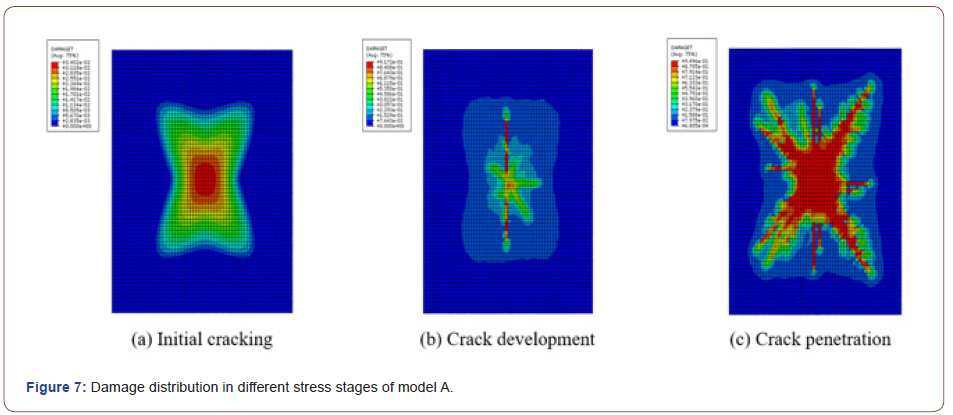
Model A: The cloud diagram of damage distribution of cast-inplace slab is shown in Figure 7. It can be seen from the figure that in the initial cracking stage, with the increase of load, damage begins to appear at the middle of the bottom span of the cast-in-place slab, and there is no visible crack at the bottom of the slab. At this time, the uniformly distributed load of the slab is about 9kN/m2; With the increase of external load, the slab enters the crack development stage. There are 0.1 ~ 0.2mm penetrating cracks at the bottom of the slab along the long side, and cracks visible to the naked eye in other directions. At this time, the maximum value of dt can reach 0.90, and the corresponding slab uniform load is about 21kN/ m2; As the load continues to increase, the slab enters the crack penetration stage. At this time, there are penetrating cracks greater than 0.2mm in all directions at the bottom of the slab, the value of dt generally greater than 0.92, and the uniformly distributed load on the slab also reaches 25kN/m2. At this time, it is considered that all the concrete at the bottom of the slab has failed.
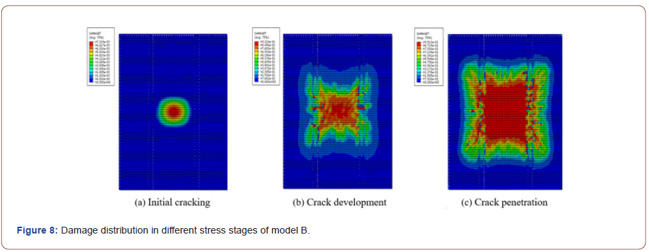
Model B: The cloud diagram of damage distribution of model B is shown in Figure 8. It can be seen from the figure that in the initial cracking stage, with the increase of load, damage begins to appear at the middle of the bottom span of the slab, and there is no visible crack at the bottom of the slab, with the maximum value of dt at about 0.1. At this time, the uniformly distributed load on the slab is about 9kN/m2; With the increase of external load, the slab enters the crack development stage, the through cracks whose width values 0.1~0.2mm appear in the mid span composite slab, and the visible cracks appear in the side span composite slab. At this time, the maximum value of dt can reach 0.90, and the corresponding slab uniform load is about 21kN/m2; As the load continues to increase, the slab enters the crack penetration stage. At this time, the crack of the mid span laminated plate passes through the post cast strip and develops to the side span composite slab. There are penetrating cracks greater than 0.2mm in all directions at the bottom of the slab, generally the value of dt is greater than 0.92, and the uniformly distributed load on the slab also reaches 24kN/m2. At this time, it is considered that all the concrete at the bottom of the slab has failed.
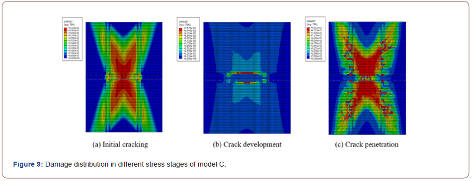
Model C: The cloud diagram of damage distribution of model C is shown in Figure 9. It can be seen from the figure that in the initial cracking stage, with the increase of load, damage begins to appear at the middle of the bottom span of the slab, and there is no visible crack at the bottom of the slab, with the maximum value of dt at about 0.2. At this time, the uniformly distributed load on the slab is about 6kN/m2; With the increase of external load, the slab enters the crack development stage, through cracks with the width of 0.1~0.2mm appear in the middle span composite slab along the short side splicing seam direction, and there are almost no cracks in the side span composite slab; As the load continues to increase, the slab enters the crack penetration stage. At this time, the crack of the mid span composite slab passes through the post cast strip and develops to the side span composite slab. There are penetrating cracks greater than 0.2mm in all directions at the bottom of the slab, but the most serious cracks are the two composite slabs in the middle span, with the maximum value of dt reaching 0.95 and the uniformly distributed load on the slab reaching 15kN/m2, At this time, it is considered that all the concrete at the bottom of the slab is invalid.
Stress analysis
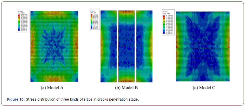
The cloud diagram of stress distribution for the three kinds of slabs in the crack penetration stage is shown in Figure 10. It can be seen from the figure that in the crack penetration stage of castin- place slab, the maximum stress is concentrated around the slab. The reason is that the four sides of the slab are fixedly supported, and the edge of the slab is in a compression state. With the increase of load, the compressive stress gradually increases; At the same time, the maximum tensile stress at the bottom of the slab is always concentrated in the middle of the span or around the splicing seam, and an obvious stress concentration area is formed between the splicing seam, which is also in line with the above damage analysis results. The splicing seam is always the weak area of the composite slab. The number of splicing seams should be reduced and arranged at the position with less stress as far as possible.
Conclusion
Based on the large-span slab encountered in a fabricated building project, ABAQUS is used to simulate the mechanical properties and failure forms of the slab when the slab adopts the whole span cast-in-place slab and the two-way composite slab with different splicing methods. The following conclusions are obtained from the finite element simulation results:
• Under the same load, the mid span displacement of the whole span cast-in-place slab is the smallest, the parallel spliced twoway composite slab is the second, and the parallel cross spliced two-way composite slab is the largest; At the same time, the ultimate load of the whole span cast-in-place slab is about 25kN/m2 which shows the best integrity; Due to the setting of parallel splicing seam, the ultimate load of parallel spliced two-way composite slab is about 24kN/m2, which is not much different from the former and shows good integrity; However, due to the two-way joint of parallel cross spliced two-way composite slab, the integrity of the composite slab is poor, and the ultimate load is about 15.8kN/m2, which is at about 1/3 lower than the first two kinds of slabs;
• With the increase of external load, plastic damage appears at the bottom of the slab. Due to the existence of splicing seam in the composite slab, stress concentration is easy to occur in this area. In particular, the strain at the splicing seam of the middle span composite slab is the largest, and the plastic damage occurs first. With the increase of the external load, the crack begins to pass through the post pouring splicing seam and develop to the side span composite slab, and finally form a through crack, and the concrete at the bottom of the slab fails under tension;
• When the slab span is 6~8m, if the truss reinforcement is used to composite slab, it is recommended to adopt the two-way composite slab, and the post cast splicing seam shall be set in the direction of less stress, and the two-way splicing seam shall not be set.
Acknowledgment
None.
Conflict of Interest
No conflict of interest.
References
- Bayasi Z, Kaiser H, Gonzales M (2001) Composite Slabs with Corrugated SIMCON Deck as Alternative for Corrugated Metal Sheets. Journal of Structural Engineering 127(10): 1198-1205.
- Izzuddin BA, Tao XY, Elghazouli AY (2004) Realistic Modeling of Composite and Reinforced Concrete Floor Slabs under Extreme Loading. I: Analytical Method. Journal of Structural Engineering 130(120): 1972-1984.
- Sang Aihua, Lin Yuanzheng (1984) Research and application of prestressed thin plate composite slab. Architectural Technology 11: 2-4+6-9.
- Guo Qijun (1984) Several problems in the design and construction of fly ash silicate industrial wallboard. Industrial Construction 7: 27-30.
- Xu Youlin, Jiang Hong, Guo Shaoxian (1993) Inspection of structural performance of double reinforced composite slab. Architectural Technology 12: 727-730.
- Ling Ru, Zhou Haichao (2016) Experiment Study on Bearing Performance of Different Types of Stitching Laminated Slabs. Journal of Anyang Institute of Technology 15(02): 37-39+68.
- (2014) Technical specification for precast concrete structures: JGJ 1-2014. Beijing: China Architecture & Building Press. (in Chinese)
- (2015) Composite slab with lattice girders ( 60 mm precast slab) : 15G366-1. Beijing: China Planning Press. (in Chinese)
- (2010) Code for design of concrete structures: GB 50010-2010. Beijing: China Architecture & Building Press. (in Chinese)
- GUO ZH, ZHANG X (1988) Experimental Investigation of Complete Stress-Deformation Curves of Concrete in Tension. Journal of Building Structures 84(4): 278-285.
- Yan JP, Guo BY (2011) A collocation method for initial value problems of second-order ODEs by using Laguerre functions. Number Math Theory Method Application 4(2): 283-295.
-
Liu Hai. Analysis of Mechanical Properties of Long-Span Reinforced Concrete Composite Slabs Under Different Splicing Methods. Glob J Eng Sci. 9(4): 2022. GJES.MS.ID.000719. DOI: 10.33552/GJES.2022.09.000719.
-
Large-span, Composite slab, Mechanical property, ABAQUS, Plastic damage
-

This work is licensed under a Creative Commons Attribution-NonCommercial 4.0 International License.


